Patent application title: Heavy-Duty Automatic Return Buffering Slide
Inventors:
Chirh-Siang Chang (Taipei City, TW)
IPC8 Class: AA47B8816FI
USPC Class:
31233444
Class name: Horizontally movable (e.g., drawer) having guide assembly and particular stop means
Publication date: 2010-03-18
Patent application number: 20100066225
Inventors list |
Agents list |
Assignees list |
List by place |
Classification tree browser |
Top 100 Inventors |
Top 100 Agents |
Top 100 Assignees |
Usenet FAQ Index |
Documents |
Other FAQs |
Patent application title: Heavy-Duty Automatic Return Buffering Slide
Inventors:
Chirh-Siang Chang
Agents:
Dr. BANGER SHIA
Assignees:
Origin: SUGAR LAND, TX US
IPC8 Class: AA47B8816FI
USPC Class:
31233444
Patent application number: 20100066225
Abstract:
A heavy-duty automatic return buffering slide comprising an external
slide, two sliding assemblies, an internal slide, a limiting rail, a
brake member and a pressure cylinder. The sliding assemblies are combined
to two sides of the external slide, respectively, and the internal slide
is provided with an engaging hook. Both sides of the internal slide are
slidably combined between the sliding assemblies. The limiting rail is
provided with a sliding groove and a lower countersink, which is
continuous with and located lower than the sliding groove. The limiting
rail is combined to the external slide. The brake member has one end
pivoted to the pressure cylinder and a top provided with an engaging
groove for cooperating with the engaging hook. The brake member is
provided with two rollers movably disposed in the sliding groove. The
pressure cylinder includes a protruding rod to push the brake member.Claims:
1. A heavy-duty automatic return buffering slide comprising:an external
slide being provided with a bottom and an opening;two sliding assemblies
being combined in the external slide;an internal slide including an
opening facing the bottom of the external slide, two opposite sides at
both sides of the opening, and a top in alignment with the opening, the
top being provided with an engaging hook between the two opposite sides
of the internal slide, both the two opposite sides of the internal slide
being slidably combined between the two sliding assemblies;a limiting
rail being provided with a sliding groove, which is continuous with a
countersink lower than the sliding groove, the limiting rail being
combined on the bottom of the external slide;a brake member being
provided at one end thereof with a pivoting portion and at a top thereof
with an engaging groove for cooperating with the engaging hook, the brake
member being further provided with two rollers, which are movably
disposed in sliding groove of the limiting rail; anda pressure cylinder
including a normally-protruding rod body having one end provided with a
pivoting portion, the pressure cylinder being pivoted to the bottom of
the external slide and combined to the brake member through the pivoting
portions of the brake member and the pressure cylinder.
2. The heavy-duty automatic return buffering slide as claimed in claim 1, wherein the sliding assemblies each include an outer board to be fixed in the external slide, the internal slide is slidably disposed on the respective outer boards.
3. The heavy-duty automatic return buffering slide as claimed in claim 1, wherein the sliding assemblies each include an outer board and an inner board, the outer boards of the sliding assemblies are fixed the sliding assemblies in the external slide, the inner boards of the sliding assemblies are slidably disposed on the outer boards of the sliding assemblies, the internal slide is slidably combined between the two inner boards.
4. The heavy-duty automatic return buffering slide as claimed in claim 1, wherein the external slide is provided with the bottom and the two opposite sides, the two opposite sides define the opening in alignment with the bottom, the sliding assemblies are combined to the two opposite sides of the external side, respectively.
Description:
BACKGROUND OF THE INVENTION
[0001]1. Field of the Invention
[0002]The present invention relates to a drawer slide, and more particularly to a heavy-duty automatic return buffering slide.
[0003]2. Description of the Prior Art
[0004]Commonly, cabinets are widely used to store items and generally provided with plural drawers. In order to make the drawers move more smoothly and easily, the respective drawers are generally provided with a slide at each of two opposite sides thereof. However, this arrangement is only suitable for the light-duty drawers but not for the heavy-duty drawers. The slides which are applied to the heavy-duty drawers are normally arranged on the bottom of the drawers to bear a heavy load, and since the bottom of the drawer has a large space, the slide can be designed to be much thicker and stronger.
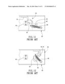
[0005]As for the drawer with the heavy-duty slides, since closing the drawer is more difficult than pulling open the drawer, a slide capable of automatically closing the drawer has been developed on the market, as shown in FIGS. 11-12, and it comprises an external slide 80 which is provided with a swing block 82 including a swivel shaft 83, a fastening groove 84 and a stop block 85. The swing block 82 is pulled by a spring 86. The external slide 85 is interiorly provided with an internal slide 90, and the internal slide 90 is provided with an engaging hook 91 for cooperating with the fastening groove 84. By such arrangements, when the drawer is pulled open along the internal slide 90, the fastening groove 84 of the swing block 82 is open toward the direction where the drawer is pulled, and one end of the spring 86 swivels with the swing block 82 in such a manner that the spring 86 is extended. When the drawer is pushed back, the engaging hook 91 touches the fastening groove 84 of the swing block 82 to make the swing block 82 swing a predetermined angle, so that the spring 86 can pull the swing block 82 to rotate back immediately, thus driving the fastening groove 84 to push the engaging hook 91 of the internal rod 90 to close the drawer. In such a structure, the automatically-return distance is limited to the extending distance of the spring 86, so that the automatic return travel is relatively shorter since the extending distance of the spring 86 is too small, and when the spring 86 and the swing block 82 are actuated, a loud noise will be caused, so that if the above structure is applied to a wardrobe in a bedroom, it is likely to wake up the sleeping person.
[0006]The present invention has arisen to mitigate and/or obviate the afore-described disadvantages.
SUMMARY OF THE INVENTION
[0007]The technical problems to be solved:
[0008]The existing heavy-duty automatic return buffering slides each utilize a swing block and a spring to offer the automatic return function, but they suffer the advantages such as: shorter automatic return travel, and loud noise.
[0009]In order to solve the above problems, a heavy-duty automatic return buffering slide in accordance with the present invention comprises an external slide, two sliding assemblies, an internal slide, a limiting rail, a brake member and a pressure cylinder. The sliding assemblies are combined to two sides of the external slide, respectively, and the top of the internal slide is provided with an engaging hook. Both sides of the internal slide are slidably combined between the sliding assemblies. The limiting rail is provided with a sliding groove and a lower countersink, which is continuous with and located lower than the sliding groove. The limiting rail is combined to the external slide. The brake member has one end pivoted to the pressure cylinder and a top provided with an engaging groove for cooperating with the engaging hook. The brake member is provided with two rollers movably disposed in the sliding groove. The pressure cylinder includes a normally-protruding rod to push the brake member.
[0010]As compared to the conventional slide, the present invention has the following advantages:
[0011]The primary objective of the present invention is to provide a heavy-duty automatic return buffering slide, whose travel depends on the length of the rod body of the pressure cylinder, the length of the rod body can be approximately half of the length of the external slide, so that the automatic return travel is increased, and the manual travel is resultantly reduced, thus saving labor.
[0012]The secondary objective of the present invention is to provide a heavy-duty automatic return buffering slide, which utilizes the pressure cylinder to gradually release the pressure, so that the external slid and the drawer can be pushed slowly without causing any noise, thus avoiding of disturbing sleeping persons.
BRIEF DESCRIPTION OF THE DRAWINGS
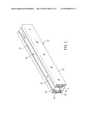
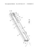
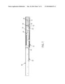
[0013]FIG. 1 is a perspective view of a heavy-duty automatic return buffering slide in accordance with the present invention;
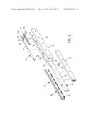
[0014]FIG. 2 is an exploded view of the heavy-duty automatic return buffering slide in accordance with the present invention;
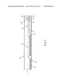
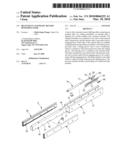
[0015]FIG. 3 is a partial view illustrating that the heavy-duty automatic return buffering slide in accordance with the present invention is to be extended;
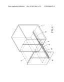
[0016]FIG. 4 is a perspective view illustrating that the heavy-duty automatic return buffering slide in accordance with the present invention is disposed on a drawer;
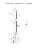
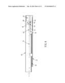
[0017]FIG. 5 is a cross-sectional view illustrating that the heavy-duty automatic return buffering slide in accordance with the present invention is to be extended;
[0018]FIG. 6 is a cross-sectional view illustrating the extending process of the heavy-duty automatic return buffering slide in accordance with the present invention;
[0019]FIG. 7 is a cross-sectional view illustrating a complete extending state of the heavy-duty automatic return buffering slide in accordance with the present invention;
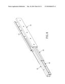
[0020]FIG. 8 is a perspective view illustrating the complete extending state of the heavy-duty automatic return buffering slide in accordance with the present invention;
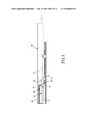
[0021]FIG. 9 is a cross-sectional view illustrating the heavy-duty automatic return buffering slide in accordance with the present invention is to be pushed back;
[0022]FIG. 10 is a cross-sectional view illustrating the push-back process of the heavy-duty automatic return buffering slide in accordance with the present invention;
[0023]FIG. 11 is an operational view of a conventional heavy-duty automatic return buffering slide; and
[0024]FIG. 12 is another operational view of the conventional heavy-duty automatic return buffering slide.
DETAILED DESCRIPTION OF THE PREFERRED EMBODIMENTS
[0025]The present invention will be clearer from the following description when viewed together with the accompanying drawings, which show, for purpose of illustrations only, the preferred embodiment in accordance with the present invention.
[0026]Referring to FIGS. 1-3, a heavy-duty automatic return buffering slide in accordance with the present invention comprises an external slide 10, two sliding assemblies 2, an internal slide 40, a limiting rail 50, a brake member 60, and a pressure cylinder 70.
[0027]The external slide 10 is provided with a bottom 11, and two opposite sides 12. The two opposite sides 12 defines an opening 13 in alignment with the bottom 11.
[0028]The two sliding assemblies 2 are combined to the respective sides 12 in the external slide 10 and each include an outer board 20 and an inner board 30.
[0029]One side of the respective outer boards 20 is fixed to the respective sides 12 of the external slide 10, and the respective inner boards 30 are movably mounted on the other side of the respective outer boards 20.
[0030]The internal slide 40 includes an opening 41 facing the bottom 11 of the external slide 10, two opposite sides 42 at both sides of the opening 41, a top 43 in alignment with the bottom 11 The top 43 is provided with an engaging hook 44 between the two opposite sides 42. Both sides 42 of the internal slide 40 are combined between the two inner boards 30 of the two sliding assemblies 2.
[0031]The limiting rail 50 is provided with a sliding groove 51 and a countersink 52, which is continuous with and located lower than the sliding groove 51. The limiting rail 50 is combined on the bottom 11 of the external slide 10 and located in the opening 41 of the internal slide 40.
[0032]The brake member 60 is provided at one end thereof with a pivoting portion 61 and at the top thereof with an engaging groove 62. The brake member 60 is further provided with two rollers 63, which are movably disposed in sliding groove 51 of the limiting rail 50. The engaging groove 62 is provided for cooperating with the engaging hook 44.
[0033]The pressure cylinder 70 includes a normally-protruding rod body 71 having one end provided with a pivoting portion 72. The pressure cylinder 70 is pivoted to the bottom 11 of the external slide 10 and combined to the brake member 60 through the pivoting portions 61, 72. The pressure cylinder 70 can be a hydraulic or a pneumatic cylinder.
[0034]Referring to FIG. 4 first, the external slide 10 is combined on a cabinet A (normally on an inner bottom of the cabinet A), and the internal slide 40 is combined to a drawer B. Opening or closing the drawer B will make the sliding assembly 2, the internal slide 40, the brake member 60 and the pressure cylinder 70 act synchronously. As shown in FIGS. 5-8, which illustrate how the internal slide 40 is extended, the engaging hook 44 is originally engaged in the engaging groove 62, so that when the internal slide 40 is pulled outwards, the brake member 60 will be synchronously driven by the internal slide 40 to move along the sliding groove 51 and compress the rod body 71 of the pressure cylinder 70. At this moment, the internal slide 40 will move out of the external slide 10 along with the inner boards 30 of the sliding assemblies 2. When the brake member 60 arrives at the countersink 52, one of the rollers 63 will sink in the countersink 52, thus causing an angular deflection of the pressure cylinder 70. With the angular deflection and countersink 52, the rod body 71 can be compressed and limited. Meanwhile, when the one of the rollers 63 of the brake member 60 sink in the countersink 52, the brake member 60 will incline to make the engaging groove 62 incline with respect to the moving direction of the brake member 60, thus causing the disengagement of the engaging hook 44 of the internal slide 40. Therefore, the internal slide 40 can be continuously pulled outwards. While the internal slide 40 is pulled outwards, with the cooperation of the outer and the inner boards 20, 30, the extending length of the internal slide 40 can be increased. As shown in FIGS. 9-10, which illustrate how the internal slide 40 is retracted, the internal slide 40 is pushed to move backwards along the sliding assemblies 2 until the engaging hook 44 touches the inclined engaging groove 62. At this moment, a pushing force will be resultantly applied to the engaging groove 62 to make the one of the rollers 63 disengage from the countersink 52, meanwhile, the brake member 60 restores to its original state to make the engaging hook 44 engage in the engaging groove 62. Therefore, the rod body 71 of the pressure cylinder 70, which is compressed, is free to release the stored energy to push the brake member 60 and the internal slide 40 inwards, thus closing the drawer B automatically.
[0035]The sliding assemblies 2 are each provided with the outer board 20 and the inner board 30 to increase the travel of the internal slide 40, or only provided with the outer board 20 to assist the sliding operation of the internal slide 40.
[0036]With the above structures, the present invention can offer the following advantages:
[0037]1. The automatic return travel in accordance with the present invention depends on the length of the rod body 71 of the pressure cylinder 70, and the length of the rod body 71 can be approximately half of the length of the external slide 10, so that the automatic return travel is increased, the manual travel is resultantly reduced, thus saving labor.
[0038]2. With the pressure cylinder 70, the pressure is gradually released, so that the external slide 10 and the drawer B can be pushed slowly without causing any noise, thus avoiding of disturbing sleeping persons.
[0039]While we have shown and described various embodiments in accordance with the present invention, it is clear to those skilled in the art that further embodiments may be made without departing from the scope of the present invention.
User Contributions:
comments("1"); ?> comment_form("1"); ?>Inventors list |
Agents list |
Assignees list |
List by place |
Classification tree browser |
Top 100 Inventors |
Top 100 Agents |
Top 100 Assignees |
Usenet FAQ Index |
Documents |
Other FAQs |
User Contributions:
Comment about this patent or add new information about this topic:
Images included with this patent application:
 |  |
 |  |
 |  |
 |  |
 |  |
 |  |
| Similar patent applications: | |
| Date | Title |
|---|---|
| 2014-02-06 | System and method for automatically drawing out a rack in domestic appliances |
| 2013-10-10 | Automated drawer slide |
| 2011-12-29 | Automatic teller machine |
| 2009-05-14 | Auto-return drawer rail |
| 2009-06-04 | Auto-return drawer rail |
| New patent applications in this class: | |
| Date | Title |
|---|---|
| 2016-05-26 | Magnetic hooking device for movable parts of furniture |
| 2016-03-17 | Drawer slider |
| 2016-02-04 | Slide rail assembly |
| 2015-12-24 | Pull-out guide |
| 2015-11-19 | Structure to prevent drawer from falling off |
| Top Inventors for class "Supports: cabinet structure" | |
| Rank | Inventor's name |
|---|---|
| 1 | Yun-Lung Chen |
| 2 | Karl-Friedrich Laible |
| 3 | Jae Hoon Lim |
| 4 | Wen-Tang Peng |
| 5 | Chen-Lu Fan |