Patent application title: DRIVE FOR ADJUSTING PARTS OF SEATING AND RECLINING FURNITURE
Inventors:
Wenli Zeng (Huizhou, CN)
IPC8 Class: AF16H2920FI
USPC Class:
74 8933
Class name: Reciprocating or oscillating to or from alternating rotary including screw and nut carriage surrounded, guided, and primarily supported by member other than screw (e.g., linear guide, etc.)
Publication date: 2010-03-18
Patent application number: 20100064830
Inventors list |
Agents list |
Assignees list |
List by place |
Classification tree browser |
Top 100 Inventors |
Top 100 Agents |
Top 100 Assignees |
Usenet FAQ Index |
Documents |
Other FAQs |
Patent application title: DRIVE FOR ADJUSTING PARTS OF SEATING AND RECLINING FURNITURE
Inventors:
Wenli ZENG
Agents:
SINORICA, LLC
Assignees:
Origin: ROCKVILLE, MD US
IPC8 Class: AF16H2920FI
USPC Class:
74 8933
Patent application number: 20100064830
Abstract:
A drive for adjusting parts of seating and reclining furniture is
provided, which includes: an electric motor, disposed within a motor
cover of a cabinet and engaged with a gear connected to a lead screw via
one end of a drive shaft of the electric motor, and a slider, for moving
rectilinearly back and forth in cooperation with the lead screw. The
slider is provided with a drive nut therein, which is screwed onto the
lead screw to enable the slider to move rectilinearly. One or more
positioning grooves are disposed on the slider in parallel with the nut.
Guide rails are correspondingly disposed in the positioning grooves. One
end of each guide rail is fixed to the cabinet and the other end of each
guide rail is fixed to a top stopper. Therefore, a better adjustability
is achieved within a limited inner space of the furniture. Moreover, the
drive does not need to move, and the stroke length of the drive is
independent from the cabinet size thereof, so that the drive has a low
manufacturing cost and is easily assembled.Claims:
1. A drive for adjusting parts of seating and reclining furniture,
comprising: an electric motor (7), disposed within a motor cover (6) of a
cabinet (3) and engaged with a gear (9) connected to a lead screw (11)
via one end of a drive shaft of the electric motor, and a slider (14),
for moving rectilinearly back and forth in cooperation with the lead
screw, wherein the slider is provided with a drive nut (141) that is
screwed onto the lead screw to enable the slider to move rectilinearly,
one or more positioning grooves (142) are disposed on the slider in
parallel with the nut, guide rails (18) and (20) are correspondingly
disposed in the positioning grooves, and one end of each guide rail is
fixed to the cabinet and the other end of each guide rail is fixed to a
top stopper (12).
2. The drive for adjusting parts of seating and reclining furniture according to claim 1, wherein a front retainer (13) is further disposed between the top stopper and the guide rails fixed on a reclining frame.
3. The drive for adjusting parts of seating and reclining furniture according to claim 1, wherein the gear engaged with the shaft of the electric motor is sleeved with a non-standard bearing (8) on one end thereof and sleeved with another bearing (10) on the other end, and the lead screw is screwed into the gear.
4. The drive for adjusting parts of seating and reclining furniture according to claim 1, wherein the slider is further disposed with a connecting device (143) for matching with an external transmission device.
5. The drive for adjusting parts of seating and reclining furniture according to claim 4, wherein the transmission device is a rocker (22) and a connecting rod (23) for rotating about an end point of the rocker in cooperation with the rocker, and the connecting rod is connected to one part of the seating and reclining furniture under adjustment.
6. The drive for adjusting parts of seating and reclining furniture according to claim 1, wherein the cabinet is disposed with a rear cover (2) at one end away from the lead screw, a lug (24) is disposed on the rear cover in a manner of being connected to and cooperating with a rear cover stopper (1) fixed on the reclining frame, and the lug is configured in one pair parallel to each other and spaced apart by a certain distance, and each lug is provided with a mounting hole (25) in the center thereof.
7. The drive for adjusting parts of seating and reclining furniture according to claim 6, wherein a center plate (4) serving to control the drive is disposed in the cabinet, and a plug fastener (21) for fixing a plug is disposed at a lead hole of the center plate on the cabinet.
8. The drive for adjusting parts of seating and reclining furniture according to claim 6, wherein the lug of the rear cover is connected to and cooperates with an external hole capable of fixing the drive to the rear cover stopper on the furniture.
9. The drive for adjusting parts of seating and reclining furniture according to any one of claims 1 to 8, wherein one of the guide rails is disposed with a groove (181) on one side surface thereof, and the groove is provided for accommodating start-stop stroke switches (15) for controlling operations of the electric motor.
10. The drive for adjusting parts of seating and reclining furniture according to claim 9, wherein the groove of the guide rail is disposed with an end cover (16) for enclosing the groove.
Description:
BACKGROUND OF THE INVENTION
[0001]1. Field of the Invention
[0002]The present invention relates to a drive for adjusting parts of seating and reclining furniture, and more particularly to a drive applicable to a chair and sofa.
[0003]2. Related Art
[0004]A drive of this kind is known from DE-GM 89 03 603, in which a mechanism, consisting of a gear connected to a spindle and a worm engaging the gear, is arranged inside a housing. The worm is driven by an electric motor fastened to a side surface of the housing. A nut, on which a lifting tube capable of moving in a lifting tube receiving device is fastened, is guided in a non-twisting manner on the spindle within the lifting tube receiving device protruding from the housing. The lifting tube can be easily adjusted if this drive is fixed in a pivoting manner via the receiving device on the housing and the lifting tube is coupled with an adjuster for slatted bases.
[0005]Such a drive is particularly disadvantageous in that, its total length is determined by a necessary minimum length for guiding the lifting tube within the lifting tube receiving device plus a lifting path of the lifting tube. This minimum length is necessary in order to reliably prevent the lifting tube from bending over a long travel paths. This means that it is necessary to simultaneously prolong the lifting tube receiving device while increasing the stroke length of the lifting tube. Therefore, it is necessary to manufacture housings with different lengths of lifting tube receiving device within certain limits, and as a result, the manufacturing of the drives becomes considerably expensive.
[0006]Furthermore, such drive cannot be used in constricted spaces unobtrusively, for example, in adjustable seating and reclining furniture.
[0007]Moreover, an adjuster has been disclosed in DE 37 34 922 A1, which is designed to be adjustable in a longitudinal direction on a special section tube by means of a nut/spindle mechanism. The nut part located within the special section tube is designed in one piece, including a sliding shell that partially surrounds the special section tube and strips guided in grooves within the special section tube. A web that reaches through the groove within the special section tube and connects these parts is provided between the nut and the sliding shell. As the sliding shell only partially surrounds the special section tube, an additional sliding support is provided, and the sliding shell and the sliding support are screwed together. A large number of individual parts definitely require considerable efforts during assembling, and meanwhile result in an increased cost.
SUMMARY OF THE INVENTION
[0008]Accordingly, the present invention is directed to a drive for adjusting parts of seating and reclining furniture to overcome the deficiencies in the prior art, which has a low manufacturing cost, is easily assembled, and a stroke length thereof can be adjusted independently.
[0009]In order to achieve the above objectives of the present invention, the following technical solutions are adopted.
[0010]A drive for adjusting parts of seating and reclining furniture is provided. The drive includes: an electric motor, disposed within a motor cover of a cabinet and engaged with a gear connected to a lead screw via one end of a drive shaft of the electric motor; and a slider, for moving rectilinearly in cooperation with the lead screw. The slider is provided with a drive nut therein, which is screwed onto the lead screw to enable the slider to move rectilinearly. One or more positioning grooves are disposed on the slider in parallel with the nut. Guide rails are correspondingly disposed within the positioning grooves. One end of each guide rail is inserted into a rear retainer and then fixed to the cabinet together with the rear retainer, and the other end of each guide rail is fixed to a top stopper.
[0011]A front retainer is further disposed between the top stopper and the guide rails.
[0012]The gear engaged with the shaft of the electric motor is sleeved with a non-standard bearing on one end thereof and sleeved with another bearing on the other end thereof. The lead screw is screwed into the gear.
[0013]The slider is disposed with a connecting device for matching with an external transmission device.
[0014]The transmission device is a rocker and a connecting rod for rotating about an end point of the rocker in cooperation with the rocker. The connecting rod is connected to one part of the seating and reclining furniture under adjustment.
[0015]The cabinet is disposed with a rear cover at one end away from the lead screw. A lug is disposed on the rear cover in a manner of being connected to and cooperating with a rear cover stopper fixed on a reclining frame. The lug is configured in one pair parallel to each other and spaced apart by a certain distance, each of which has a mounting hole in the center thereof.
[0016]A center plate serving to control the drive is disposed in the cabinet. A plug fastener for fixing a plug is disposed at a lead hole of the center plate on the cabinet.
[0017]One of the guide rails is disposed with a groove on one side surface thereof. The groove is provided for accommodating start-stop stroke switches that are used for controlling operations of the electric motor.
[0018]The groove of the guide rail is disposed with an end cover for enclosing the groove.
[0019]Through the above technical solutions, the present invention has the following beneficial effects.
[0020]The drive of the present invention has a better adjustability within a limited inner space of the furniture. Moreover, the drive does not need to move, and the stroke length of the drive is independent from the cabinet size, so that the drive has a lower manufacturing cost and is easily assembled.
BRIEF DESCRIPTION OF THE DRAWINGS
[0021]The present invention will become more fully understood from the detailed description given herein below for illustration only, and thus is not limitative of the present invention, and wherein:
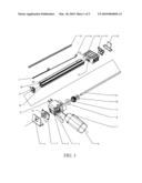
[0022]FIG. 1 is a three-dimensional assembled view of a drive for adjusting parts of seating and reclining furniture according to the present invention;
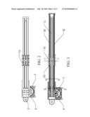
[0023]FIG. 2 is a front view of a drive for adjusting parts of seating and reclining furniture according to the present invention;
[0024]FIG. 3 is a sectional view of a drive for adjusting parts of seating and reclining furniture according to the present invention;
[0025]FIG. 4 is a sectional view of a drive for adjusting parts of seating and reclining furniture according to the present invention, taken along A-A in FIG. 3;
[0026]FIG. 5 is a sectional view of a drive for adjusting parts of seating and reclining furniture according to the present invention, taken along B-B in FIG. 3;
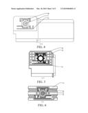
[0027]FIG. 6 is a sectional view of a drive for adjusting parts of seating and reclining furniture according to the present invention, taken along C-C in FIG. 3;
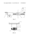
[0028]FIG. 7 is a schematic view of a first connection mode among a drive for adjusting parts of seating and reclining furniture, an transmission device, and a rear cover stopper according to the present invention;
[0029]FIG. 8 is a sectional view taken along D-D in FIG. 7;
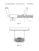
[0030]FIG. 9 is a schematic view of a second connection mode among a drive for adjusting parts of seating and reclining furniture, an transmission device, and a holding arm according to the present invention; and
[0031]FIG. 10 is a sectional view taken along E-E in FIG. 9.
DETAILED DESCRIPTION OF THE INVENTION
[0032]The present invention is described in detail below with reference to the accompanying drawings.
[0033]Referring to FIGS. 1 to 8, a drive for adjusting parts of seating and reclining furniture according to the present invention includes: an electric motor 7, disposed within a motor cover 6 of a cabinet 3 and engaged with a gear 9 connected to a lead screw 11 via one end of a drive shaft of the electric motor; and a slider 14, for moving rectilinearly back and forth in cooperation with the lead screw. The slider is provided with a drive nut 141 therein, which is screwed onto the lead screw to enable the slider to move rectilinearly. Two positioning grooves 142 are disposed on the slider in parallel with the nut. An upper guide rail 18 and a lower guide rail 20 are correspondingly disposed within each positioning groove. The upper guide rail is disposed with a groove 181 on one side surface thereof. The groove is provided for accommodating stroke switches 15 that are used for controlling operations of the electric motor. One end of each of the two guide rails is fixed to the cabinet and the other end of the guide rail is fixed to a top stopper 12. A front retainer 13 is further disposed between the top stopper and the guide rails. The gear engaged with the shaft of the electric motor is sleeved with a non-standard bearing 8 on one end thereof and sleeved with another bearing 10 on the other end thereof. The lead screw is screwed into the gear.
[0034]The slider is disposed with a connecting device 143 for matching with an external transmission device. The transmission device is a rocker 22 and a connecting rod 23 for rotating about an end point of the rocker in cooperation with the rocker. The connecting rod is connected to one part of the seating and reclining furniture under adjustment. One end of the rocker is rotatably connected to the connecting rod, and the other end is fixed to the connecting device on the slider. The connecting device is a protrusion on the slider and has a through hole in the center thereof, as shown in FIGS. 7 and 8. In addition, the cabinet is disposed with a rear cover 2 at one end away from the lead screw. A lug 24 is disposed on the rear cover in a manner of being connected to and cooperating with a rear cover stopper 1 fixed on the frame. The lug is configured in one pair parallel to each other and spaced apart by a certain distance, each of which has a mounting hole 25 in the center thereof. The lug of the rear cover is connected to and cooperates with the rear cover stopper, and the other surface of the rear cover stopper is fixed to the furniture. In addition, a center plate 4 serving to control the drive is disposed in the cabinet. A plug fastener 21 for fixing a plug is disposed at a lead hole of the center plate on the cabinet. The groove of the guide rail is disposed with an end cover 16 for enclosing the groove.
[0035]During assembly, the lead screw 11 is screwed into the gear 9. Then, the non-standard bearing 8 is mounted at a big-end bearing seat of the gear, and the bearing 10 is mounted at a small-end bearing seat of the gear. Then, the obtained component is inserted into the cabinet 3 via a left hole of the cabinet, and the rear cover 2 is covered. Then, a rear retainer 19 is sleeved on the lead screw, and the slider 14 is screwed onto the lead screw. Then, the stroke switches 15 are installed and locked within the groove of the upper guide rail 18, and then, the end cover 16 is covered. The above component configured in one piece passes through the slider 14, and one end of the lower guide rail 20 passes through the positioning groove of the slider, both of which are fastened to the rear retainer 19 at the same time, then inserted into the cabinet together, and locked through using four screws. Thereafter, the front retainer 13 is snapped into the other end of the upper guide rail 18 and the lower guide rail 20, and the top stopper 12 and the front retainer are locked to the guide rails. Afterwards, the center plate 4 is inserted into the cabinet, and the electric motor 7 is locked to the cabinet. Then, the motor cover 6 is mounted on the cabinet, and the plug fastener 21 is locked to the cabinet. Finally, the rear cover stopper 1 is snapped to a lug seat of the rear cover.
[0036]In usage, once being powered on, the electric motor rotates and the shaft drives the lead screw to rotate. Under the motion of the lead screw, the nut on the slider is translated on the lead screw, which enables the slider to translate on the guide rails. Since two stroke switches are disposed in the groove of one guide rail, the operations of the electric motor are controlled by the two stroke switches, thereby controlling the translation distance of the slider. Since one end of the transmission device is fixed to the slider, the rocker of the transmission device is driven to move at the same time as the slider is translationally moved. The movement of the rocker drives the connecting rod to rotate at a certain angle, thereby driving the reclining part of the furniture under adjustment to move.
[0037]Alternatively, as for the drive for adjusting parts of seating and reclining furniture, the rocker of its transmission device may be fixed to a connecting device 143' at another position on the slider, as shown in FIGS. 9 and 10. Compared with the first embodiment, the transmission device here is also a small protrusion having a through hole in the center thereof. However, it is not connected to the middle position of the slider via an iron sheet protruding from the connecting rod. Instead, the rocker is directly connected to the middle position of the slider.
[0038]Definitely, the number of the guide rail may also be one rather than two, and the sectional shape of the guide rail may be either round or square. Some ribs matching with the slider may be disposed on the surface of the guide rail, and grooves may be correspondingly disposed on the slider, thereby achieving a more reliable engagement.
[0039]Compared with the prior art, the present invention enables the slider to slide on the lead screw to drive the transmission device, thereby adjusting the elevation of the reclining part of the furniture. Therefore, a relatively better adjustability is achieved within the limited inner space of the furniture. Moreover, the drive does not need to move, and the stroke length of the drive is independent from the cabinet size thereof, so that the drive has a low manufacturing cost and is easily assembled.
User Contributions:
comments("1"); ?> comment_form("1"); ?>Inventors list |
Agents list |
Assignees list |
List by place |
Classification tree browser |
Top 100 Inventors |
Top 100 Agents |
Top 100 Assignees |
Usenet FAQ Index |
Documents |
Other FAQs |
User Contributions:
Comment about this patent or add new information about this topic:
| People who visited this patent also read: | |
| Patent application number | Title |
|---|---|
| 20100066815 | Stereo pair and method of making stereo pairs |
| 20100066812 | IMAGE PICKUP APPARATUS AND IMAGE PICKUP METHOD |
| 20100066811 | STEREO VISION SYSTEM AND CONTROL METHOD THEREOF |
| 20100066810 | MOBILE TERMINAL HAVING A PANORAMA PHOTOGRAPHING FUNCTION AND METHOD FOR CONTROLLING OPERATION THEREOF |
| 20100066809 | Deployable Image Sensor |
Images included with this patent application:
 |  |
 |  |
 |  |
| Similar patent applications: | |
| Date | Title |
|---|---|
| 2009-06-18 | Adjusting device for seating and reclining furniture |
| 2012-05-10 | Rack and pinion arrangement for a mining extraction machine and rack and pinion rod therefor |
| 2008-10-23 | Device for adjusting the tension of a pulling element |
| 2010-10-14 | Steering device for adjusting a wheel steering angle |
| 2010-06-17 | Drive for a coffee brewing device and coffee brewing device |
| New patent applications in this class: | |
| Date | Title |
|---|---|
| 2016-01-28 | Linear module with a support device |
| 2015-02-12 | Serially-connected ball screw pair and piezoelectric actuator macro-micro driving and guiding device |
| 2014-10-09 | Anti-rotation device for linear actuator and linear actuator comprising same |
| 2013-07-25 | Power seat sliding apparatus |
| 2013-06-27 | Angle adjusting mechanism |
| Top Inventors for class "Machine element or mechanism" | |
| Rank | Inventor's name |
|---|---|
| 1 | Yoshimitsu Miki |
| 2 | Bo Long |
| 3 | Matthias Reisch |
| 4 | Wolfgang Rieger |
| 5 | Craig S. Ross |