Patent application title: TEST APPARATUS FOR TESTING CIRCUIT BOARD
Inventors:
Chun-Hung Chou (Tu-Cheng, TW)
Assignees:
HON HAI PRECISION INDUSTRY CO., LTD.
IPC8 Class: AG01R3102FI
USPC Class:
324754
Class name: Fault detecting in electric circuits and of electric components of individual circuit component or element with probe elements
Publication date: 2010-03-04
Patent application number: 20100052712
Inventors list |
Agents list |
Assignees list |
List by place |
Classification tree browser |
Top 100 Inventors |
Top 100 Agents |
Top 100 Assignees |
Usenet FAQ Index |
Documents |
Other FAQs |
Patent application title: TEST APPARATUS FOR TESTING CIRCUIT BOARD
Inventors:
Chun-Hung Chou
Agents:
PCE INDUSTRY, INC.;ATT. Steven Reiss
Assignees:
HON HAI PRECISION INDUSTRY CO., LTD.
Origin: CITY OF INDUSTRY, CA US
IPC8 Class: AG01R3102FI
USPC Class:
324754
Patent application number: 20100052712
Abstract:
The disclosure relates to a test apparatus for testing a circuit board.
The circuit board includes a connector and a plurality of test points
connected to the connector via a plurality of lines and the connector of
the circuit board is connected to the plurality of lines via a plurality
of corresponding signal pins. The test apparatus includes a circuit, a
connector, a plurality of probes, and a tester. The circuit includes a
plurality of test points and lines connecting to the test points
correspondingly. The connector is coupled to the connector of the circuit
board. The plurality of probes contact with the test points of the test
apparatus. The tester sends test-signals to the connector of the circuit
board via the lines correspondingly, receives test-information on the
test points of the circuit board via the connectors, analyzes the
test-information, and generates a test-result of the circuit board.Claims:
1. A test apparatus for testing a circuit board which comprises a
connector and a plurality of test points connected to the connector via a
plurality of lines, the connector of the circuit board being connected to
the plurality of lines via a plurality of corresponding signal pins, the
test apparatus comprising:a circuit, comprising a plurality of test
points and lines connecting to the test points correspondingly;a
connector for being coupled to the connector of the circuit board;a
plurality of probes, for contacting with the test points of the test
apparatus; anda tester, for sending test-signals to the connector of the
circuit board via the lines correspondingly, receiving test-information
on the test points of the circuit board via the connectors, analyzing the
test-information, and generating a test-result of the circuit board.
2. The test apparatus as recited in claim 1, wherein the test points are arranged in a line on the circuit.
3. The test apparatus as recited in claim 1, wherein the connector of the test apparatus comprises a plurality of signal pins, and the number of the signal pins is equal to the number of test points of the test apparatus.
4. The test apparatus as recited in claim 3, wherein the number of the signal pins of the connector of the test apparatus is the same as that of the signal pins of the connector of the circuit board.
5. The test apparatus as recited in claim 4, wherein the connector of the test apparatus is configured to connect to the connector of the circuit board via the signal pins.
Description:
BACKGROUND
[0001]1. Technical Field
[0002]The disclosure relates to a test apparatus for testing a circuit board and, more particularly, to a test apparatus for testing a high-density integrated circuit board.
[0003]2. Description of the Related Art
[0004]Generally, a circuit board is tested using a probe. The probe of a tester directly contacts each test point on the circuit board. However, the test points of the circuit board may be densely packed and irregularly arranged on the circuit board. Accordingly, it is difficult to accurately wield the test probe. Furthermore, because testing is performed manually, the process is often time intensive.
BRIEF DESCRIPTION OF THE DRAWINGS
[0005]The components in the drawings are not necessarily drawn to scale, the emphasis instead being placed upon clearly illustrating the principles of the test apparatus for testing the circuit board. Moreover, in the drawings, like reference numerals designate corresponding parts throughout the several views.
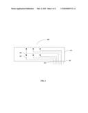
[0006]FIG. 1 is a schematic diagram of a circuit board under test in accordance with an exemplary embodiment.
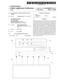
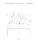
[0007]FIG. 2 is a schematic diagram of a test apparatus for testing the circuit board of FIG. 1, in accordance with an exemplary embodiment.
DETAILED DESCRIPTION
[0008]FIG. 1 is a schematic diagram of a circuit board 100 under test in accordance with an exemplary embodiment. The circuit board 100 under test includes a test circuit 101 and a connector 107. The test circuit 101 includes a plurality of test points 103 needing to be tested and corresponding lines 105 connecting the test points 103 to the connector 107. The connector 107 includes a plurality of signal pins 109 connected to the lines 105. The number of the signal pins 109 is equal to the number of the test points 103. In another exemplary embodiment, the test points 103 are divided into several groups. Accordingly, the circuit board 100 includes several connectors 107 in accordance with the number of the groups of test points 103.
[0009]FIG. 2 is a schematic diagram of a test apparatus 200 for testing the circuit board 101 of FIG. 1. The test apparatus 200 includes an interconnecting circuit board 202 and a tester 213. The interconnecting circuit board 202 includes a circuit 201 and a connector 207. The circuit 201 includes a plurality of test points 203 and corresponding lines 205 connecting the test points 203 to the connector 207. The test points 203 may be arranged as desired. In the exemplary embodiment, the test points 203 are arranged in a line on the interconnecting circuit board 202. The connector 207 includes a plurality of signal pins 209 which are connected to the lines 205. The number of the signal pins 209 is equal to the number of the test points 203, and is also equal to the number of the signal pins 109 of the connector 107. The tester 213 includes a plurality of probes 211 which are configured for testing the test points 103 of the circuit 101. In another exemplary embodiment, the circuit board 100 includes several connectors 107 and the interconnecting circuit board 202 includes the same number of connectors 207 as the circuit board 100.
[0010]When utilizing the test apparatus 200 to test the circuit board 100, the connector 207 of the interconnecting circuit board 202 is coupled to the connector 107 of the circuit board 100, and the test points 103 are coupled to the test points 203 correspondingly. The probes 211 of the tester 213 contact the test points 203 and the tester 213 sends test-signals to the connector 207 via the lines 205. The connector 207 transmits the test-signals to the connector 107 and the connector 107 transmits the test-signals to the test points 103 via the lines 105. The circuit board 100 generates and feeds back test-information on the test points 103 to the connector 107 via the lines 105. The connector 107 transmits the test-information to the connector 207 and the connector forwards the test-information to the tester 213 via the lines 205. The tester 213 analyzes the test-information and generates a test-result of the circuit board 100. Because the test points 203 of the interconnecting circuit board 202 can be arranged as desired, it is easy to adjust configuration of the points that will be most efficient and convenient for testing a densely packed integrated circuit board, and avoid having to directly probe irregularly arranged test points of the circuit board.
[0011]It is understood that the disclosure may be embodied in other forms without departing from the spirit thereof. Thus, the present examples and embodiments are to be considered in all respects as illustrative and not restrictive, and the disclosure is not to be limited to the details given herein.
User Contributions:
comments("1"); ?> comment_form("1"); ?>Inventors list |
Agents list |
Assignees list |
List by place |
Classification tree browser |
Top 100 Inventors |
Top 100 Agents |
Top 100 Assignees |
Usenet FAQ Index |
Documents |
Other FAQs |
User Contributions:
Comment about this patent or add new information about this topic:
Images included with this patent application:
 |  |
 |
| Similar patent applications: | |
| Date | Title |
|---|---|
| 2012-06-21 | Testing apparatus for testing ports of printed circuit board |
| 2012-05-17 | Apparatus for thermal testing of a printed circuit board |
| 2011-01-27 | Test apparatus, additional circuit and test board |
| 2011-07-14 | Test apparatus, additional circuit and test board |
| 2009-01-29 | Apparatus for testing chips with ball grid array |
| New patent applications in this class: | |
| Date | Title |
|---|---|
| 2010-12-02 | Thin-film probe sheet and method of manufacturing the same, probe card, and semiconductor chip inspection apparatus |
| 2010-11-25 | Rf performance test structure with electronic switch function |
| 2010-10-21 | Differential signal probing system |
| 2010-10-21 | Closed-grid bus architecture for wafer interconnect structure |
| 2010-10-21 | Test and measurement instrument and method of configuring using a sensed impedance |
| New patent applications from these inventors: | |
| Date | Title |
|---|---|
| 2012-09-27 | Electronic device for detecting a type of a charger device during a sleep mode |
| 2012-04-19 | Computer mouse and operating method thereof |
| 2012-04-12 | Computer mouse and method thereof |
| 2009-10-22 | Electronic device and information transmission method thereof |
| 2009-09-17 | Electrical adapter assembly and apparatus using the same |
| Top Inventors for class "Electricity: measuring and testing" | |
| Rank | Inventor's name |
|---|---|
| 1 | Udo Ausserlechner |
| 2 | David Grodzki |
| 3 | Stephan Biber |
| 4 | William P. Taylor |
| 5 | Markus Vester |