Patent application title: Cylinder generator
Inventors:
Young Ho Ro
Agents:
Young Ho Ro
Assignees:
Ro; Young Ho
Origin: GLEN BURNIE, MD US
IPC8 Class: AH02K2100FI
USPC Class:
310 83
Patent application number: 20100052444
Abstract:
New design of generator and or generators, which creates electricity.
Using a sphere shape design compared to the traditional generator designs
already in use today. Using a sphere shape design for the placements of
the magnets and coils. The gears will allow for multiple layers to be
used for rotation, dependent on power needs.
Claims:
1. Using a cylinder shape design compared to the traditional generator
designs already in use today.
2. Using a cylinder shape design for the placements of the magnets and
coils. The gears will allow for multiple layers to be used for rotation,
dependent on power needs.
Description:
CLAIM OF PRIORITY
[0001]This application claims the benefit of U.S. Provisional Application
Ser. No. 61/136421 filed on Sep. 4, 2008, the entire contents of which
are hereby Incorporated by reference.
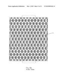
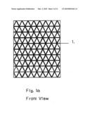
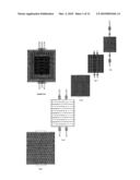
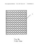
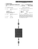
[0002]FIG. 1 shows the magnet cylinder, known as magnet cylinder 1. Which
consist of a cylinder shape metal framing (FIG. 1a) around a light weight
cylinder shaped material, connected by a support rod, that provide the
external force needed to rotate the magnet sphere 1. FIG. 1 shows gear 1
and gear 2 connected to the support rod at both ends. The external force
moves the magnet cylinder 1 to a clockwise rotation. FIG. 1 also shows
the placement of the magnets, which are arranged in a north, south order,
within the given roll.
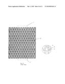
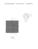
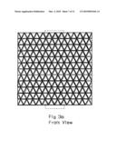
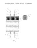
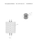
[0003]FIG. 2 shows a ceramic cylinder framing (FIG. 2a), which supports
the copper wiring. Which is placed around the magnet cylinder 1. Each
copper wire coil, is connected to the opposite corresponding copper wire
coil and or will remain independent. Positioning will be determined
during testing,.either at the opposite end of the corresponding top or
bottom, left or right hemisphere or within the same hemisphere. Each
section of coils may also be independent. (Positive to one rod 1 and
negative to the other rod 2. The next coil connected to the rods,
negative to rod 1 and positive to rod 2.) The positive and negative, will
be determined by the inter sphere. And as long as there is a draw from
the Rod 1 and Rod 2, with less resistance, the electron will not flow to
the next coil. Without using a commutator. Which ever generates the
highest power output. To be determined during testing. Rods tubes 1 and 2
are fixed on top of the top hemisphere, with gear 1 and gears 2
connected. Within rod tubes 1 and 2, are rods 1 and 2, which is the
output for the corresponding hemisphere. Rods tubes 3 and 4 are fixed on
the bottom of the bottom hemisphere, with gear 3 and gear 4 connected.
Within rod tubes 3 and 4, are rods 3 and 4, which is the output for the
corresponding hemisphere. Gears 1,2,3, and 4 rotate freely without
movement of the coil cylinder. Gears 1 and 2 are connected to magnet
cylinder gear 1, and gear 3 and 4 are connected to magnet cylinder gear
2. This will cause ceramic gears 1 and 2 to rotate counterclockwise to
magnet cylinder gear 1, which rotates clockwise and cylinder gear 3 and 4
also rotates counterclockwise to magnet cylinder 2, which rotates
clockwise, as the ceramic coil sphere remains still. (shown on Page 12)
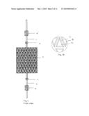
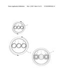
[0004]FIG. 3 shows the outer-magnet cylinder, known as magnet cylinder 2.
Which also consist of a cylinder shape metal framing (FIG. 3a), fixed
around the wire coil. Fixed on the top and bottom of the magnet cylinder
2, are gear 1 and gear 2, which rotates the magnet cylinder 2
counterclockwise. The placement of the magnets arranged to the
corresponding magnetic field of the magnet cylinder 1, all within the
inside of magnet cylinder 2. If needed, magnets can be placed on the
outside of the cylinder to create multiple layers.
[0005]FIG. 4 shows another coil cylinder, known as cylinder coil 2. This
is to increase power output. Components are similar to the FIG. 2, with
it's corresponding gear as shown page 8.
[0006]FIG. 5 shows another magnet cylinder 3, fixed around the cylinder
coil 2. With its similar gears as magnet cylinder 2. As shown on page 10.
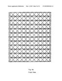
[0007]Page 12 shows the rotation of the gears as stated with gear FIG. 1,
gears FIG. 2, and gear FIG. 3. Also shows the rotation of the gears as
stated with gear FIG. 1, gears FIG. 4, and FIG. 5. This rotation of the
gears will rotate the corresponding cylinder.
FUNCTION
[0008]The rotation of the magnet cylinder 1 and the rotation of magnet
cylinder 2, creates the electricity when it passes the corresponding
copper wire coil.
comments("1"); ?>
comment_form("1"); ?>