Patent application title: Pinata expandable to a plurality of positions
Inventors:
Yong Moon Cho (Hacienda Heights, CA, US)
Changjoo J. Lee (Santa Clarita, CA, US)
IPC8 Class: AA63H3700FI
USPC Class:
446 5
Class name: Amusement devices: toys having portions knocked apart or awry by impact including portion serving as container for diverse articles (e.g., pinata)
Publication date: 2009-12-31
Patent application number: 20090325454
Inventors list |
Agents list |
Assignees list |
List by place |
Classification tree browser |
Top 100 Inventors |
Top 100 Agents |
Top 100 Assignees |
Usenet FAQ Index |
Documents |
Other FAQs |
Patent application title: Pinata expandable to a plurality of positions
Inventors:
Yong Moon Cho
Changjoo J. Lee
Agents:
CALIF KIP TERVO
Assignees:
Origin: SAN DIEGO, CA US
IPC8 Class: AA63H3700FI
USPC Class:
446 5
Patent application number: 20090325454
Abstract:
Expandable pinata is a decorative container constructed from sheet
materials connected at the edges, which can be shipped and stored flat.
An internal expandable brace is activated by pulling external cords that
draw brace into the expanded position, causing pinata body to flex into a
three-dimensional body with fillable chamber. Score lines optionally
direct flexing into a faceted shape. Lock mechanism holds brace in the
erect configuration, with adjustable degree of expansion. Pinata body is
resilient and compresses brace, to engage lock automatically and maintain
expanded configuration.Claims:
1. An expandable pinata, including:a body, comprising:a front face
including:a border;a central portion; including:an outer surface; andan
inner surface; anda hole piercing said central portion from said outer
surface to said inner surface;a back face including:a border;a central
portion; including:an outer surface; andan inner surface; anda hole
piercing said central portion from said outer surface to said inner
surface; wherein said front face and said back face are attached to each
along substantially their complete respective borders such that said
front face and said back face are movable relative to each other between
a first position, wherein said front and back faces are close together,
and a second position wherein said central portions of said front and
back faces are at least twice as far apart as in the first position; said
pinata body being biased toward the first position; anda brace mechanism
for moving said body from the first position to the second position and
for bracing said body in the second position, comprising:an expandable
frame movable between a first position and a second position;
including:an attached wall attached to said inner surface of one said
face;lock means for maintaining said frame in the second position;a front
end of cord attached to said frame and extending through said hole
piercing said front central portion; anda back end of cord attached to
said frame and extending through said hole piercing said back central
portion; and wherein:said front and back ends of cord are each connected
with said frame such that pulling said front and back ends of cord apart
urges said frame and said pinata body from the first position to the
second position.
2. The pinata of claim 1, said lock means comprising:a selectively adjustable-detent means that engages automatically when said expandable frame is moved from the first position to the second position.
3. The pinata of claim 2, said detent means including:a plurality of spaced-apart, generally parallel strips attached to said attached wall of said frame for cooperatively engaging a different portion of said frame so as to retain said frame in a second position, with a plurality of selectable degrees of expansion.
4. The pinata of claim 1, said front and said back faces further including:score lines for causing said front and back faces to bend in a predesigned manner when said pinata is moved from the first position to the second position.
5. An expandable pinata, including:a container comprising:a front face including:a border; anda central portion; including:an outer surface; andan inner surface; anda back face including:a border; anda central portion; including:an outer surface; andan inner surface;said front face and said back face being attached to each other along substantially their complete respective peripheries to define a cavity between said faces with at least one access hole for filling said cavity; anda brace mechanism including:a moveable frame disposed in said cavity between said faces, for bracing said pinata in an expanded position;selective lock means for retaining said pinata in a selected one of a plurality of available expanded positions; andhandle means for moving said frame from a first flat position to a second expanded position.
6. The pinata of claim 5, said brace mechanism comprising:a hinge member attached to a first said inner surface; including:a lock end; includingcooperative lock means for locking said brace mechanism in the expanded position;a free end;a hinge between said lock and free ends; anda slot near said free end;a prop member connected to said hinge member, including:a lock end; including:cooperative lock means for locking said brace mechanism in the expanded position;a support end; anda slot between said lock and support ends, for engaging with said hinge member slot to connect said hinge member to said prop member; andhandle means, including:at least one length of cord connected to said brace mechanism and interacting with said brace mechanism such that pulling the ends of said cord moves said brace mechanism from the flat position to the expanded position.
7. The pinata of claim 6, wherein: said container is biased toward the flat position such that said container tends to compress said moveable frame when in the expanded position.
8. The pinata of claim 7; said hinge member cooperative lock means comprising:a plurality of detent strips attached to said lock end of said hinge member with small gaps between said detent strips; such that said prop member lock end will snap into each small gap sequentially as said brace mechanism is moved from the flat position to the expanded position.
9. The pinata of claim 8, wherein said moveable frame is formed into a shape that is an isosceles triangle in the expanded position.
10. The pinata of claim 8, said handle means including:a hole near the center of each said front central portion;a first cord attached to said lock end of said prop member and passing through said hole in a first said central portion such that pulling said first cord from outside said container causes said lock end of said prop member to be dragged across said plurality of detent strips; anda second cord attached to said support end of said prop member and passing through said hole in a second said central portion such that: pulling said second cord causes said support end of said prop member to be pulled away from and perpendicular to said first inner surface; and such that: pulling said second cord from outside said container causes said support end to push said second central portion to move apart from said first central portion such that said pinata is moved from a flat position to an expanded position.
11. An expandable pinata, including:a body enclosing a cavity comprising:a front face including:a border; anda central portion; including:an outer surface; andan inner surface; anda back face including:a border; anda central portion; including:an outer surface; andan inner surface; andat least one hole through one said central portion; said front face and said back face being attached to each other along substantially their complete respective peripheries to define a cavity between said faces; anda brace mechanism including:a moveable frame disposed in said cavity between said central portions; anda cord including:an internal portion connected to said frame within said cavity;a midsection disposed through said hole; andan external portion accessible outside said central portion; said cord connected to said frame such that pulling on said external portion moves said frame from a close position wherein said central portions are close together to an expanded position wherein said frame holds said central portions at least twice as far apart as in the close position
Description:
FIELD OF THE INVENTION
[0001]The present invention relates in general to an expandable decorative article and more particularly to an expandable pinata with internal bracing mechanism.
BACKGROUND OF THE INVENTION
[0002]Pinatas are hollow decorative vessels that can be filled with candy or other small gifts. A filled pinata is typically suspended by a rope and children strike at it with a stick until the pinata is broken open to release the gifts inside.
[0003]Originally, pinatas had a body made of low-fired clay. More recently, pinata bodies came to be made of papier-mache over a cardboard armature. A conventional current pinata body is a hollow, frangible, three-dimensional vessel that is typically covered with fringed tissue paper and streamers. A filler hole in the upper portion of the body is left accessible for inserting the gifts or candy just before use. A hanger is also usually provided for attaching the pinata to some sort of pulley arrangement so that the pinata may be moved as a blindfolded person attempts to strike it.
[0004]Pinatas used in the United States are mostly imported. Transportation costs are a very substantial portion of the retail price of a pinata in the US. Pinatas are made to be easily broken, so careful handling en route is required to prevent premature breakage or damage to the tissue paper covering. Pinatas may be stacked somewhat during transportation, but they often have odd shapes that do not stack efficiently, such as four-legged animals or stars with seven large points radiating in all directions. Care must be taken that the pinatas are not stacked too high or move about during transport, because the hollow central bodies are easily crushed or pierced, making them unusable.
[0005]The cost of pinatas could be considerably less if they were easier to transport in bulk from a factory to the point of sale. Once sold to an end user, it is further desirable that a pinata be easier to transport to the place of use without damage to its usefulness or decorative appeal.
SUMMARY OF THE INVENTION
[0006]The present invention is an expandable pinata that may be shipped in a flat state and expanded to a three-dimensional hollow configuration by a user. The pinata body is constructed of flat, flexible panels joined along their edges.
[0007]Between the flat panels is attached an expandable brace mechanism that includes strings extending through small holes in the centers of the flat panels. The strings are pulled apart to expand the brace mechanism, which in turn forces apart the centers of the panels. The flat panels may simply bend into an expanded configuration, or scored sections of the panels may move relative to each other to create a faceted shape.
[0008]The pinata body thus becomes three-dimensional and hollow, ready to accept filling. A lock means, such as notches and tabs on the brace mechanism, maintains the pinata in a tautly expanded position so that it is easily breakable.
[0009]The expandable pinata is easily shipped in a flat configuration so that a hundred pinatas can fit in a carton that would hold only a handful of conventional pinatas. Transportation and handling costs are thus greatly reduced.
[0010]The novel pinata body is created by semi-automated manufacturing. The flat panels may be die cut from decorative stock such that the entire pinata body does not need to be covered with tissue paper. Simplified manufacturing decreases the cost of the pinata and makes it easier to ship, because there is little fragile covering to be damaged.
[0011]Similar design and construction methods can be used to create light-weight, three-dimensional decorative articles for other purposes, such as advertising displays.
[0012]The features and advantages of the invention will be readily understood when the detailed description thereof is read in conjunction with the drawings wherein like reference numerals refer to like parts throughout.
BRIEF DESCRIPTION OF THE DRAWINGS
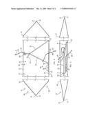
[0013]FIG. 1 is a perspective view of the pinata of the present invention in expanded position, with a portion of brace frame indicated in phantom.
[0014]FIG. 2 is a cross-sectional side view, partly cut away, taken along line 2-2, of the pinata of FIG. 1, locked in expanded configuration.
[0015]FIG. 3 is a cross-sectional side view similar to FIG. 2 but with the pinata in flat configuration.
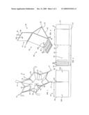
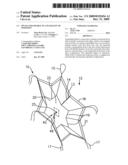
[0016]FIG. 4 is a perspective side view of the brace mechanism of FIG. 1, in expanded position.
[0017]FIG. 5 is a top view of two components of the frame of brace mechanism, disassembled and flattened.
DETAILED DESCRIPTION OF THE INVENTION
[0018]FIG. 1 is a perspective view of a preferred embodiment of pinata 10 of the present invention in an expanded position, ready for use. Pinata 10 also has a flat position in which pinata 10 is easily stored or shipped.
[0019]Pinata 10 includes a body 12 defining an internal hollow cavity 13. Cavity 13 may be filled with candy by pouring the candy into filler opening 14. Hanger 15 is attached to the top of pinata body 12 for attaching pinata 10 to a rope or other means for hanging pinata 10. The exemplary pinata 10 is in the shape of a six-pointed star with decorative streamers 17 attached to the points of the star.
[0020]Optional garland or other decoration, not shown, may outline the edges and angles of the star to obscure and close filler opening 14. To fill cavity 13, optional garland may be pulled aside to expose filler opening 14. Garland is replaced over filler opening 14 after cavity 13 is filled.
[0021]Pinata body 12, as shown in FIG. 1, has a front face 20. To enhance the three-dimensional appearance of pinata 10 in the expanded position, front face 20 includes score lines 19. The function of score lines 19 will be explained below.
[0022]Front face 20 includes a border 21, that is, a perimeter or edge, and a center portion 22. Center portion 22 has an outer surface 23, an inner surface 24 (FIG. 2), and a small hole 25 that goes through center portion 22, creating an opening communicating between inner surface 24 and outer surface 23, which is about 0.2 to 0.4 inch in diameter.
[0023]FIG. 2 is a cross-sectional side view, taken along line 2-2, of pinata 10 and brace mechanism 40 of FIG. 1, locked in expanded configuration. FIG. 3 is a cross-sectional side view similar to FIG. 2, but with the pinata in flat configuration.
[0024]Back face 30, seen partly cut away in FIG. 2, is generally identical to front face 20. Back face 30 similarly includes border 31, center portion 32, outer surface 33, inner surface 34, and a small hole 35 that goes through center portion 32, creating an opening communicating between inner surface 34 and outer surface 33, which is about 0.2 to 0.4 inch in diameter.
[0025]Front and back faces 20,30 are typically of identical outline (in mirror image, in the case of a non-symmetrical design). Front and back faces 20,30 are aligned such that their borders 21,31 are adjacent at all points. Borders 21,31 are attached together, such as by applying a strip of tape 16 such that half of the width of tape 16 is adhered to each border 21,31. Tape 16 may be transparent or may have a decorative appearance that matches or complements the appearance of front and back faces 20,30.
[0026]Front and back inner surfaces 24,34 face each other and cooperatively define hollow cavity 13. Cavity 13 is for filling with candy or small gifts and is accessible through filler opening 14.
[0027]Expandable pinata 10 further includes brace mechanism 40, partially shown in phantom in FIG. 1 and in side view in FIGS. 2 (expanded) and 3 (flat). Brace mechanism 40 generally includes an expandable brace frame 44 movable between a first flat position and a second expanded position. Brace frame 44 includes an attached wall 42 attached to inner surface 24 of front face 20, cooperative lock means 45 for locking brace frame 44 in the expanded position, and handle means 47 for moving brace mechanism from flat to expanded position.
[0028]Brace mechanism 40 is attached between front and back inner surfaces 24,34 and is movable between a first flat position and a second expanded position. When brace mechanism 40 is in the flat position as shown in FIG. 3, front inner surface 24 and back inner surface 34 of pinata 10 are close together, typically 1.0-1.5 inches apart if pinata 10 is suspended from hanger 15, or 0.5-0.75 inch apart if multiple pinatas 10 are stacked. Slight resilience in the components of brace mechanism 40 and front and back faces 20,30 result in pinata 10 being less than entirely flat if there is no compressive force applied to the flat pinata 10.
[0029]To move brace mechanism 40 from the flat to the expanded position, handle means 47 is provided so that a user can expand brace mechanism 40 from outside pinata 10. In the preferred embodiment shown in the figures, handle means 47 includes a front cord 48 attached to brace frame 44 and extending through a hole 25 in front face 20, and also a back cord 49 attached to a different portion of brace frame 44 and extending through a hole 35 in back face 30.
[0030]Pulling front cord 48 and back cord 49 apart results in brace mechanism 40 expanding and forcing front and back central portions 22,32 to move apart from each other. Borders 21, 31 remain attached to each other. Thus, front and back faces 20,30 must flex in some manner such that faces 20,30 are not planar. In the case of some feasible designs for pinata 10, front and back faces 20,30 simply curve as brace mechanism 40 forces center portions 22,32 apart.
[0031]In the design illustrated in the figures, front and back faces 20,30 include scored lines 19 to direct the bending of faces 20,30 to occur mainly along scored lines 19. Properly laid-out scored lines 19 enhance the three-dimensional appearance of pinata 10 when expanded, allow easier movement between flat and expanded positions, and decrease the stress on tape 16, making the attachment between faces 20,30 unlikely to fail under tension. Inclusion of scored lines 19 results in front and back central portions 22,32 remaining relatively flat when pinata 10 is in expanded position.
[0032]The exemplary preferred embodiment of brace mechanism 40 as shown in FIGS. 1-3 may be more easily understood with reference to FIGS. 4 and 5. FIG. 4 is a perspective side view of brace mechanism 40 in expanded position. FIG. 5 is a top view of two components 50 of exemplary preferred brace frame 44.
[0033]Referring especially now to FIG. 5, brace frame 44 preferably comprises two main components 50, such as hinge member 51 and prop member 61. Members 51, 61 are typically die-cut from corrugated cardboard or other suitably stiff but resilient material.
[0034]Hinge member 51 is typically 12 to 14 inches long and 3 to 5 inches wide. Hinge member 51 includes a free end 57, a lock end 55, and a hinge 52 between free end 57 and lock end 55. Hinge 52 is typically a scored line in the approximate center of hinge member 51, as shown in the illustrations, or could alternatively be a flexible tape joining two separate halves of hinge member 51, or any suitable hinge means.
[0035]Hinge member 51 further includes slot 53 near free end 57, hole 54, and cooperative lock means 45 such as detent strips 56 attached to lock end 55. Detent strips 56 are attached to lock end 55 parallel to hinge 52 and with small gaps between them
[0036]Prop member 61 is typically 7 to 9 inches long and 3 to 5 inches wide. Prop member 61 includes a support end 66 and a lock end 65. Prop member 61 further includes slot 63, hole 64L near lock end 65, and hole 64S near support end 66.
[0037]Slots 53 and 63 are located on their respective components 50 such that the distance d between hinge 52 and slot 53 of hinge member 51 is substantially equal to the distance d between lock end 65 and slot 63 of prop member 61.
[0038]Brace frame components 50 are easily die cut, hole punched, and scored by automated or semi-automatic machinery. Detent strips 56 may also be cut and attached to hinge member 51 by machinery, or the cutting of detent strips 56 may be automated and the attachment, such as by gluing, may be done by hand.
[0039]To begin the manufacture of expandable pinata 10, components are cut and assembled to form brace mechanism 40. Components 50 are cut and scored and handle means 47 such as two lengths of cord are provided. Detent strips 56 are attached to lock end 55 by any suitable means, such as adhesive.
[0040]Brace frame 44 is assembled by crimping hinge 52, then engaging slots 53 and 63 by sliding hinge member 51 and prop member 61 together, as is well known. To complete brace mechanism 40, handle means 47 are connected to brace frame 44.
[0041]In the case of the exemplary preferred embodiment of brace mechanism 40 illustrated herein, handle means 47 comprises a front cord 48 and back cord 49. Front cord 48 is typically at least 12 inches long and back cord 49 may be shorter, such as about 8 inches long.
[0042]Referring back to FIG. 2, front cord 48 is knotted at one end and the other end is inserted through hole 64L in prop member 61 and then through hole 54 in hinge member 51. Back cord 49 is knotted at one end and the other end is inserted through hole 64S. Threading of front and back cords 48,49 through holes 54, 64S, and 64L is best done with brace frame 44 in an expanded position, that is, with hinge 52 open by at least 30 degrees internal angle.
[0043]Pinata body 12 is typically assembled by putting tape 16 along borders 21,31. Brace mechanism 40 is then inserted through filler opening 14 and attached inside pinata body 12, such as by attaching attached wall 42 to inner surface 24 with suitable adhesive means.
[0044]The free end (the end not attached to brace mechanism 40) of front cord 48 is inserted through hole 25 in front face 20, from inside 24 to outside 23, then the free end is knotted so that it cannot slip back through hole 25.
[0045]Similarly, the free end (not attached to brace mechanism 40) of back cord 49 is inserted through hole 35 of back face 30, from inner surface 34 to outer surface 33, then the free end is knotted so that back cord 49 cannot slip back through hole 35.
[0046]Front and back faces 20,30 are attached together by aligning their respective borders 21,31 with inner surfaces 24,34 together, then borders 21,31 are attached with suitable means such as adhesive, adhesive tape, or staples. Adhesive tape with a decorative outer surface, such as tape 16, is preferred because tape 16 both attaches front and back faces 20,30 together and covers the cut edges 21,31 and any gaps between front and back faces 20,30. Cooperating slots may be cut into front and back faces 20,30 to create filler opening 14 as shown in FIG. 1.
[0047]Front and back faces 20,30 are preferably cut from light cardboard faced with aluminized Mylar. This type of decorative cardboard is widely used for gift boxes, Christmas decorations, and other goods. The aluminized Mylar is shiny, colorful, and may include "optical effects," that is, diffraction lines that produce sparkly multicolored patterns. Tape 16 is preferably an adhesive-backed paper or plastic tape with an outer surface of aluminized Mylar that matches or harmonizes with the decorative surface of faces 20,30. The aluminized Mylar has the additional benefit of making the cellulosic base material of faces 20,30 more resilient and resistant to being scratched or scuffed in shipment.
[0048]Pinata 10 remains in flat position for attachment of hanger 15 and optional decoration, such as streamers 17 and garland (not shown), as are well known in the art. Pinata 10 may then be packed in flat position for shipping and retail sales.
[0049]To expand pinata 10 for use or display, front cord 48 and back cord 49 are pulled in opposite directions, that is, each cord 48,49 is pulled straight out from the hole 25,35 from which it protrudes. Cords 48,49, which are threaded through brace frame 44, push and pull brace frame 44 into the expanded position.
[0050]As support end 66 is pulled away from attached wall 42, hinge 52 opens and lock end 65 of prop member 61 is urged toward lock end 55 of hinge member 51. With further pulling of cords 48,49, lock end 65 is dragged across detent strips 56. The resilience of all the materials used in pinata 10 tends to press lock end 65 toward attached wall 42 and cause lock end 65 to snap into each gap between detent strips 56 as lock end 65 is dragged over strips 56. Each "snap" into a gap provides a slightly different degree of expansion of brace mechanism 40 and, thus, of pinata body 12. Although the pinata is described herein as having a flat and an expanded position, the expanded position is actually a set of positions providing a selectively adjustable degree of expansion.
[0051]Detent strips 56 are typically attached to lock end 55 of hinge member 51 such that the distance between hinge 52 and the middle detent position is d. Thus, if lock end 65 is urged to the second "snap," or middle detent position, the central portion of brace frame 44 is an equilateral triangle, as viewed from the edges. The base of the triangle is attached wall 42, which is attached to inner surface 24 of front face 20. Extending above the triangle is support end 66 of prop member 61. Support end 66 contacts inner surface 34 of back face 30 and braces back face 30 in the expanded position, relative to attached wall 42.
[0052]If lock end 65 is urged to the first or third detent position, the edge view of the central portion of brace frame 44 will be an isosceles triangle, having a base that is slightly larger or smaller than the sides.
[0053]After brace mechanism 40 is locked in the expanded position, it resists accidental collapse well because compressive force is exerted on brace mechanism 40 by front and back faces 20,30 pressing lock end 65 against detent strip 56. Pinata 10 has a distinct bias toward the flat position because front and back faces 20, 30 are attached together in the flat position. Deviation from the flat position, wherein inner surfaces 24,34 are about an inch apart, strains pinata body 12 and creates a mild compressive force on whatever is within cavity 13.
[0054]In fact, if it is desired to collapse expanded pinata 10 to the flat position, it may be necessary to reach inside cavity 13 to manipulate brace mechanism 40 by hand in order to unlock it.
[0055]When pinata body 12 is in the expanded position, body 12 is typically at least 7 inches thick. Cavity 13 has sufficient volume for filling with candy or gifts and pinata 10 has a generously three-dimensional appearance, enhanced by the facets created by score lines 19. Pinata 10 is then filled and used in the normal manner.
[0056]It can be seen that other decorative objects may be manufactured using very similar components. For example, light weight hanging advertisement displays may be shipped flat and expanded quickly by using an internal brace mechanism identical or similar to the mechanism shown and described herein. Such hanging displays would be simpler and quicker to assemble than many conventional displays.
[0057]Expandable ornaments for a house, other than pinatas, can be produced in a similar manner. Examples of such ornaments can be as exotic as collapsible lanterns or vases, provided suitable materials are used. Body 12 and brace mechanism 40 may be modified and arranged in many ways but still retain the uses and benefits described.
[0058]Brace mechanism 40 may alternatively be located within cavity 13 other than between center portions 22,32. If brace mechanism 40 is suitably attached inside body 12, it is not necessary that handle means 47 communicate directly with brace mechanism 40 via holes 25,35. Handle means 47 may in this case be grippable portions of the exterior of body 12.
[0059]The brace mechanism described herein can also be used between faces that are not connected along their edges. Thus a three-dimensional shape with "square" instead of faceted sides could be created.
[0060]Although particular embodiments of the invention have been illustrated and described, various changes may be made in the form, composition, construction, and arrangement of the parts herein without sacrificing any of its advantages. Therefore, it is to be understood that all matter herein is to be interpreted as illustrative and not in any limiting sense, and it is intended to cover in the appended claims such modifications as come within the true spirit and scope of the invention.
User Contributions:
comments("1"); ?> comment_form("1"); ?>Inventors list |
Agents list |
Assignees list |
List by place |
Classification tree browser |
Top 100 Inventors |
Top 100 Agents |
Top 100 Assignees |
Usenet FAQ Index |
Documents |
Other FAQs |
User Contributions:
Comment about this patent or add new information about this topic:
Images included with this patent application:
 |  |
 |
| Similar patent applications: | |
| Date | Title |
|---|---|
| 2012-11-01 | Expandable play set |
| 2013-05-02 | Light-emitting building block having electricity connection unit |
| 2010-08-19 | Pivotally manipulable toy |
| 2013-01-03 | Bubble maker for personal mobility devices |
| 2013-01-03 | Producing sound and vibration |
| New patent applications in this class: | |
| Date | Title |
|---|---|
| 2016-05-12 | Semi-assemblable pinata having an automatically closing center |
| 2014-02-20 | Portable pinata pole assembly |
| 2013-12-19 | Reusable pinata with spring loaded latches |
| 2013-12-05 | Reusable pinata |
| 2013-09-12 | Pinata toy |
| Top Inventors for class "Amusement devices: toys" | |
| Rank | Inventor's name |
|---|---|
| 1 | Robert H. Mimlitch, Iii |
| 2 | David Anthony Norman |
| 3 | Michael Nuttall |
| 4 | Stacy Lynn O'Connor |
| 5 | Joel Reagan Carter |