Patent application title: METHOD FOR CONTROLLING A FACILITY FOR TREATING EXHAUST GASES FROM AN INTERNAL COMBUSTION ENGINE
Inventors:
Francois Fresnet (Nanterre, FR)
Nathalie Leiglon (Paris, FR)
Assignees:
RENAULT S.A.S.
IPC8 Class: AF01N900FI
USPC Class:
60286
Class name: Internal combustion engine with treatment or handling of exhaust gas by means producing a chemical reaction of a component of the exhaust gas condition responsive control of heater, cooler, igniter, or fuel supply of reactor
Publication date: 2009-12-31
Patent application number: 20090320455
Inventors list |
Agents list |
Assignees list |
List by place |
Classification tree browser |
Top 100 Inventors |
Top 100 Agents |
Top 100 Assignees |
Usenet FAQ Index |
Documents |
Other FAQs |
Patent application title: METHOD FOR CONTROLLING A FACILITY FOR TREATING EXHAUST GASES FROM AN INTERNAL COMBUSTION ENGINE
Inventors:
Francois Fresnet
Nathalie Leiglon
Agents:
OBLON, SPIVAK, MCCLELLAND MAIER & NEUSTADT, L.L.P.
Assignees:
RENAULT S.A.S
Origin: ALEXANDRIA, VA US
IPC8 Class: AF01N900FI
USPC Class:
60286
Patent application number: 20090320455
Abstract:
A facility for treating exhaust gases from an internal combustion engine
(1) comprises catalytic oxidation means (3), a particle filter (4) placed
downstream from the catalytic oxidation means (3), a reformer (5) to
produce reformate. The reformate is introduced with the exhaust gases
upstream of the catalytic oxidation means in order to obtain a pre-set
recommended temperature Tcons of the gases heated upstream of the
particle filter (4), so as to regenerate the particle filter (4) by
raising the temperature of the gases, a calculated reformate flow
Qref_calc is determined as a function of the recommended temperature
Tcons, a discrepancy coefficient is determined as a function of the
difference between the recommended temperature Tcons and a measured
temperature Tmes upstream of the particle filter, and the reformer (5) is
controlled with a recommended reformate flow Qref_cons as a function of
the discrepancy coefficient a and the calculated reformate flow
Qref_calc.Claims:
1. A method for control of an exhaust-gas treatment installation of an
internal combustion engine (1), wherein the installation is provided with
catalytic oxidation means (3), a particulate filter (4) disposed
downstream from the catalytic oxidation means (3), means for measuring a
temperature Tmes of the heated gases upstream from the particulate
filter (4) and a reformer (5) for producing a reformate, in which method
the reformate is introduced with the exhaust gases upstream from the
catalytic oxidation means to obtain a predetermined setpoint temperature
Tset of the heated gases upstream from the particulate filter (4),
in such a way as to regenerate the particulate filter (4) by raising the
temperature of the gases, a calculated flow Qref.sub.--.sub.calc of
reformate is determined according to the setpoint temperature Tset,
a difference coefficient is determined according to the difference
between the setpoint temperature Tset and the measured temperature
Tmes upstream from the particulate filter, and the reformer (5) is
controlled with a setpoint flow Qref.sub.--.sub.set of reformate
according to the difference coefficient α and the calculated flow
Qref.sub.--.sub.calc of reformate.
2. A method according to claim 1, wherein the calculated flow Qref.sub.--.sub.calc is determined according to the change of enthalpy of the gases due to the input of energy from oxidation of the reformate.
3. A method according to claim 1, wherein the calculated flow is determined by the formula: Q ref _ calc = C exh Q exh ( T set - T exh ) Δ H H 2 η H 2 + Δ H CO η CO - C ref M ref ( T set - T ref ) ##EQU00006## in which:Qexh is the mass flow of exhaust gases at the engine outlet;Texh is the temperature of the exhaust gases;Cexh is the specific heat capacity of the exhaust gases;Tref is the temperature of the reformate;Cref is the specific heat capacity of the reformate;ΔHH2 is the enthalpy change during oxidation of one mole of hydrogen;ΔHCO is the enthalpy change during oxidation of one mole of carbon monoxide;Tset is the setpoint temperature upstream from the particulate filter;ηCO is the molar fraction of carbon monoxide in the reformate;ηH2 is the molar fraction of hydrogen in the reformate;Mref is the molar mass of the reformate.
4. A method according to claim 1, wherein the difference coefficient is determined by the formula: α = T mes - T up T set - T up ##EQU00007## in which Tup is the temperature of the gaseous mixture upstream from the catalytic oxidation means (3).
5. A method according to claim 4, wherein the setpoint flow Qref.sub.--.sub.calc is the ratio of the calculated flow Qref.sub.--.sub.calc to the difference coefficient α.
6. A method according to claim 5, wherein, if the measured temperature Tmes is very different from the setpoint temperature Tset, the setpoint flow is the calculated flow.
7. A method according to claim 6, wherein it is considered that the measured temperature Tmes is very different from the setpoint temperature Tset if the difference coefficient α is smaller than 0.7.
8. A method according to claim 1, wherein the setpoint flow Qref.sub.--.sub.calc is based on a value of predetermined maximum flow Qmax.
9. A method according to claim 1, wherein the catalytic oxidation means are a nitrogen oxides trap (3).
Description:
[0001]The invention relates to a method for control of an exhaust-gas
treatment installation of an internal combustion engine, especially of a
motor-vehicle engine.
[0002]The heterogeneity of combustion processes in engines with lean mixture, especially in Diesel engines, has the effect of generating carbon particles, which cannot be burned efficiently in the engine. That is manifested, for example, by the discharge of black smoke at the outlet of the exhaust line. This phenomenon is a source of pollution that one is attempting to reduce.
[0003]The presence of a particulate filter in the exhaust line of the engine makes it possible to decrease considerably the amount of particles, dust and other forms of soot discharged into the atmosphere and to satisfy the anti-pollution standards.
[0004]Regeneration procedures make it possible periodically to burn the particles trapped in the filter and to avoid clogging thereof. The soot particles are substantially carbon-containing species, and their combustion consumes oxygen to form carbon dioxide.
[0005]Combustion of soot in the particulate filter is induced by raising the temperature of the exhaust gases within the particulate filter to a temperature on the order of 550 to 650° C., the temperature at which combustion of carbon particles retained in the filter is initiated.
[0006]Filter regeneration is controlled by a calculator, which determines whether regeneration must take place and, when it is in progress, whether it may continue.
[0007]To initiate and maintain regeneration, there is frequently used a method that consists in modifying the operating conditions of the engine to raise the temperature of the exhaust gases before they are passed into the particulate filter. These modifications often involve fuel injection, which may be delayed for at least one combustion chamber of the engine. Likewise, in certain cases, post-injection of fuel is effected during the final phase of the expansion stroke. This latter injection does not supply any additional mechanical power to the engine, but it raises the temperature of the exhaust gases.
[0008]These methods have the disadvantage of being very intrusive as regards the functioning of the engine and of significantly increasing the fuel consumption. In addition, because of a phenomenon known as dilution, they increase the fuel concentration in the lubricating oil.
[0009]Sometimes the exhaust-gas treatment installations also contain nitrogen oxides (NOx) traps, which capture the nitrogen oxides generated during combustion. During a desorption operation under reducing conditions, the nitrogen oxides are reduced to nitrogen and liberated.
[0010]Furthermore, the document US2005/0103001 A1 proposes, for an internal combustion engine, an exhaust-gas treatment installation provided with a first oxidation catalyst, followed in the direction of circulation of the exhaust gases by a nitrogen oxide trap and a particulate filter. The installation is additionally provided with a reformer, with which a reformate can be generated from the vehicle fuel. Upon command, the reformate is injected upstream from one of the aforesaid components. The reformate is rich in hydrogen (H2) and carbon monoxide (CO). When it is injected upstream from the oxidation catalyst, the reformate undergoes oxidation with the oxygen contained in the exhaust gases, generating heat. This heat is used to raise the temperature of the exhaust gases upstream from the particulate filter and to induce regeneration thereof. When the reformate is injected upstream from the nitrogen oxide trap, it is also oxidized by the oxygen of the exhaust gases, just as on an oxidation catalyst. In fact, in common with the oxidation catalyst, the nitrogen oxides trap is provided with metals capable of oxidizing hydrogen and carbon monoxide in the presence of oxygen.
[0011]If the amount of reformate injected is insufficient, the temperature attained upstream from the particulate filter will be insufficient to initiate and maintain regeneration.
[0012]If on the contrary it is excessive, the risk exists that the installation temperature will rise to a level destructive for the installation.
[0013]An objective of the invention is therefore to propose a control method making it possible to guarantee control of regeneration of the particulate filter without the risk of damaging the installation.
[0014]With this objective in view, the invention is applicable to an exhaust-gas treatment installation of an internal combustion engine, the installation comprising catalytic oxidation means, a particulate filter disposed downstream from the catalytic oxidation means, means for measuring a temperature Tmes of the gases upstream from the particulate filter and a reformer for producing a reformate. The object of the invention is a control method, wherein the reformate is introduced with the exhaust gases upstream from the catalytic oxidation means to obtain a predetermined setpoint temperature Tset of the heated gases upstream from the particulate filter, in such a way as to regenerate the particulate filter by raising the temperature of the gases, a calculated flow of reformate is determined according to the setpoint temperature Tset, a difference coefficient is determined according to the difference between the setpoint temperature Tset and the measured temperature Tmes upstream from the particulate filter, and the reformer is controlled with a setpoint flow of reformate according to the difference coefficient and the calculated flow of reformate.
[0015]By means of a model of the oxidation of the reformate, it is possible to predict a temperature upstream from the particulate filter according to a flow of reformate and of exhaust gas. In this way the calculated flow of reformate can be determined immediately, as soon as the regeneration cycle of the particulate filter has been initiated. Furthermore, by adding closed-loop servo-control and by applying the setpoint flow, corrected according to the difference coefficient, the differences between the model and the real dynamics of the temperature upstream from the particulate filter are taken into account. The measurement differences are also corrected. Even if the model is simplified and does not take all the real parameters into account, it is possible to obtain a temperature upstream from the particulate filter close to the desired temperature necessary to achieve regeneration, without reaching levels that would be destructive.
[0016]In particular manner, the calculated flow is determined according to the change of enthalpy of the gases due to the input of energy from oxidation of the reformate. The temperature model is based only on the input of energy of the reformate to the exhaust gases. This model is simple to use, and it yields satisfactory results.
[0017]In this case, the calculated flow Qref--.sub.calc can be determined by the formula:
Q ref _ calc = C exh Q exh ( T set - T exh ) Δ H H 2 η H 2 + Δ H CO η CO - C ref M ref ( T set - T ref ) ##EQU00001##
in which:Qexh is the mass flow of exhaust gases at the engine outlet;Texh is the temperature of the exhaust gases;Cexh is the specific heat capacity of the exhaust gases;Tref is the temperature of the reformate;Cref is the specific heat capacity of the reformate;ΔHH2 is the enthalpy change during oxidation of one mole of hydrogen;ΔHCO is the enthalpy change during oxidation of one mole of carbon monoxide;Tset is the setpoint temperature upstream from the particulate filter;ηCO is the molar fraction of carbon monoxide in the reformate;ηH2 is the molar fraction of hydrogen in the reformate;Mref is the molar mass of the reformate.
[0018]By way of example, the difference coefficient is determined by the formula:
α = T mes - T up T set - T up ##EQU00002##
in which Tup is the temperature of the gaseous mixture upstream from the catalytic oxidation means.
[0019]In particular manner, the corrected flow is the ratio of the setpoint flow to the difference coefficient.
[0020]If the measured temperature is equal to the setpoint temperature, the difference coefficient is equal to 1, and so no correction is applied to the setpoint flow. If the measured temperature is lower than the setpoint temperature, the difference coefficient is smaller than 1, and so the setpoint flow is greater than the calculated flow.
[0021]According to an improvement of the method, if the measured temperature is very different from the setpoint temperature, the setpoint flow is the calculated flow. This limits potential excursions of the setpoint value that could generate oscillation phenomena or large ranges of variation of temperature.
[0022]For example, it is considered that the measured temperature is very different from the setpoint temperature if the difference coefficient is smaller than 0.7.
[0023]According to another improvement, the corrected flow is based on a value of predetermined maximum flow. This avoids giving the reformer a setpoint flow that it could not maintain.
[0024]According to a particular embodiment, the catalytic oxidation means are a nitrogen oxides trap. The nitrogen oxides trap contains metals having a catalytic function capable of causing the desired reactions of oxidation of the reformate. The energy exchanges during desorption in the nitrogen oxides trap are negligible and do not impair application of the method according to the invention.
[0025]The method will be better understood and other particular features and advantages will become apparent on reading the description hereinafter, the description referring to the attached drawings, wherein:
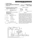
[0026]FIG. 1 is a diagram of an installation implementing the method according to the invention;
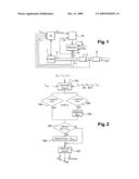
[0027]FIG. 2 is a flow diagram representing the method according to the invention.
[0028]An exhaust-gas treatment installation of a motor vehicle engine is shown schematically in FIG. 1. The installation is provided with an internal combustion engine 1, an exhaust manifold 2 that channels the exhaust gas to a nitrogen oxides trap 3, and a particulate filter 4, which receives the gases emerging from nitrogen oxides trap 3. The installation is also provided with a reformer 5, which produces reformate from the air and the vehicle fuel, such as diesel oil. A reformate conduit 8 channels the reformate to exhaust manifold 2 upstream from nitrogen oxides trap 3. Reformer 5 may be of any known type, such as a steam reformer, a partial-oxidation reformer or an auto-thermal reformer.
[0029]Reformer 5 is provided with a reformer calculator 10, which controls reformer 5 so that it generates the desired flow of reformate having the desired richness. The installation is also provided with an engine calculator 9, which controls engine 1, and especially the injection of fuel. Engine calculator 9 receives information about the state or functioning of engine 1 from transducers. In addition, it receives temperature information from temperature transducers such as thermocouples: an exhaust-gas temperature Texh measured in exhaust manifold 2, a mixture temperature Tup upstream from nitrogen oxides trap 3 and downstream from the connection of reformate conduit 8 to exhaust manifold 2, and a temperature Tmes of the heated gases upstream from the particulate filter. Furthermore, the reformer calculator receives a reformate temperature Tref, measured in reformate conduit 8.
[0030]When engine 1 is running, it generates exhaust gases, which are evacuated via exhaust manifold 2 then via nitrogen oxides trap 3 and finally via particulate filter 4. When reformer calculator 10 determines that it is necessary to regenerate particulate filter 4, it commands reformer 5 to generate reformate to be injected into the exhaust gases. The reformate passes through nitrogen oxides trap 3 and undergoes oxidation with the oxygen contained in the exhaust gases. The oxidation is caused by the presence of catalysts in nitrogen oxides trap 3, in a manner known in itself. The oxidation causes liberation of an amount of energy that acts to raise the temperature of the exhaust gases upstream from the particulate filter. The gases heated in this way pass into particulate filter 4 and, by virtue of their temperature, cause regeneration of the particle filter by combustion of the soot trapped in the filter. A setpoint temperature Tset, at which regeneration can be achieved without damaging the installation, is predetermined for the heated gases.
[0031]Engine calculator 9 transmits to reformer calculator 10 all the information necessary for its operation, especially the measured temperatures such as described hereinabove and the estimated or measured exhaust-gas flow Qexh. When regeneration of particulate filter 4 is commanded, the method according to FIG. 2 is implemented in order to determine the reformate flow to be generated. In step 101, there is determined a calculated flow according to the formula:
Q ref _ calc = C exh Q exh ( T set - T exh ) Δ H H 2 η H 2 + Δ H CO η CO - C ref M ref ( T set - T ref ) ##EQU00003##
in which:Qref--.sub.calc is the calculated flow of reformate, in kg/s;Qexh is the mass flow of exhaust gases at the engine outlet, in kg/s;Texh is the temperature of the exhaust gases, in K;Cexh is the specific heat capacity of the exhaust gases, in J/kg/K;Tref is the temperature of the reformate, in K;Cref is the specific heat capacity of the reformate, in J/kg/K;ΔHH2 is the enthalpy change during oxidation of one mole of hydrogen, in J/mole;ΔHCO is the enthalpy change during oxidation of one mole of carbon monoxide, in J/mole;Tset is the setpoint temperature upstream from the particulate filter, in K;ηCO is the molar fraction of carbon monoxide in the reformate;ηH2 is the molar fraction of hydrogen in the reformate;Mref is the molar mass of the reformate, in kg/mol.
[0032]These last three variables ηCO, ηH2, Mref can be determined by reformer calculator 10 by consulting stored correspondence tables and using as input the operating point of reformer 5 such as defined by the richness of the air/fuel mixture to be reformed and the reformate flow. The same is true for the heat capacities Cexh, Cref of the exhaust gases and reformate.
[0033]There is also calculated the difference coefficient:
α = T mes - T up T set - T up ##EQU00004##
[0034]Thereafter, in step 102, it is determined whether the difference coefficient is larger than a predetermined threshold, such as 0.7. In this case, there is determined, in step 103, a setpoint flow according to the formula:
Q ref _ set = Qref_calc α ##EQU00005##
[0035]If, as determined in step 104, the difference coefficient is smaller than the predetermined threshold value, step 105 is undertaken directly. This step also is undertaken after step 103. During step 105, it is determined whether the setpoint flow exceeds a maximal flow Qmax predetermined according to the capacities of the installation. If such is the case, the calculated flow is replaced in step 106 by the maximal flow Qmax, so as to limit the setpoint value.
[0036]In step 107, the setpoint flow is subdivided into a richness command and an air-flow command for reformer 5. If applicable, one of the foregoing commands may be combined with a fuel-flow command, depending on the type of command accepted by reformer 5.
[0037]These steps 101 to 107 are repeated cyclically as long as regeneration is necessary.
[0038]The invention is not limited to the embodiment described above merely by way of example. The nitrogen oxides trap may be replaced by other means for catalytic oxidation of the reformate, such as an oxidation catalyst. The setpoint temperature Tset may evolve in the course of regeneration.
User Contributions:
comments("1"); ?> comment_form("1"); ?>Inventors list |
Agents list |
Assignees list |
List by place |
Classification tree browser |
Top 100 Inventors |
Top 100 Agents |
Top 100 Assignees |
Usenet FAQ Index |
Documents |
Other FAQs |
User Contributions:
Comment about this patent or add new information about this topic:
| People who visited this patent also read: | |
| Patent application number | Title |
|---|---|
| 20100095489 | METHOD FOR THE PRODUCTION OF AN ADHESIVE CLOSURE DEVICE TOGETHER WITH APPARATUS AND ADHESIVE CLOSURE DEVICE PRODUCED ACCORDINGLY |
| 20100095488 | COVER LATCHING MECHANISM |
| 20100095487 | GRIPPING SLEEVE DEVICE FOR PRECISION INSTRUMENTS |
| 20100095486 | HINGE ASSEMBLY WITH RESTRICTING UNIT |
| 20100095485 | OPENING-AND-CLOSING MECHANISM |
Images included with this patent application:
 |  |
| Similar patent applications: | |
| Date | Title |
|---|---|
| 2013-06-27 | System and method for controlling oxygen emissions from a gas turbine |
| 2012-05-10 | Combined air turbine starter, air-oil cooler, and fan |
| 2013-07-11 | Flushing the exhaust gas recirculation lines of a gas turbine |
| 2012-02-23 | Method and system for homogenizing exhaust from an engine |
| 2013-07-11 | Control systems and methods for super turbo-charged engines |
| New patent applications in this class: | |
| Date | Title |
|---|---|
| 2018-01-25 | Electric exhaust-gas catalytic converter, vehicle and method for operating an electric exhaust-gas catalytic converter |
| 2018-01-25 | Exhaust system for a compression ignition engine comprising a water adsorbent material |
| 2017-08-17 | Urea mixer |
| 2017-08-17 | Method and apparatus for controlling an internal combustion engine coupled to an exhaust aftertreatment system |
| 2017-08-17 | Scr after-treatment of engine exhaust gas |
| New patent applications from these inventors: | |
| Date | Title |
|---|---|
| 2009-12-17 | Exhaust line of a diesel engine and desulfation method |
| Top Inventors for class "Power plants" | |
| Rank | Inventor's name |
|---|---|
| 1 | Gabriel L. Suciu |
| 2 | Patrick Benedict Melton |
| 3 | Eugene V. Gonze |
| 4 | Thomas Edward Johnson |
| 5 | Jan Hodgson |