Patent application title: METHOD AND APPARATUS FOR EXERCISING
Inventors:
James L. Hern (St. Petersburg, FL, US)
IPC8 Class: AA63B2102FI
USPC Class:
482124
Class name: Utilizing resilient force resistance and user supplied counter force attached to user
Publication date: 2009-12-17
Patent application number: 20090312163
Inventors list |
Agents list |
Assignees list |
List by place |
Classification tree browser |
Top 100 Inventors |
Top 100 Agents |
Top 100 Assignees |
Usenet FAQ Index |
Documents |
Other FAQs |
Patent application title: METHOD AND APPARATUS FOR EXERCISING
Inventors:
James L. Hern
Agents:
LARSON AND LARSON
Assignees:
Origin: LARGO, FL US
IPC8 Class: AA63B2102FI
USPC Class:
482124
Patent application number: 20090312163
Abstract:
An application for an exercise device includes a belt member adapted to be
worn around a mid-section of a user and at least one back strap, a first
end of each back strap connected to a rear section of the belt member.
Two resilient members are provided, a first end of each resilient member
is affixed to a distal end of the back straps and two handles are
attached to a distal end of each resilient member. The two handles are
configured to accommodate a hand of the user while the user, wearing the
exercise device, alternately or concurrently pushes against the force of
the resilient members.Claims:
1. An exercise device comprising:a belt member, the belt member adapted to
be worn around a mid-section of a user;at least one back strap, a first
end of each back strap connected to a rear section of the belt member;two
resilient members, a first end of each resilient members affixed to a
distal end of the at least one back strap; andtwo handles, a distal end
of each resilient member affixed to one of the two handles, the two
handles configured to accommodate a hand of the user.
2. The exercise device of claim 1, further comprising two shoulder cushions, the shoulder cushions covering at least an underside of the at least one back strap at a location in which the at least one back strap interfaces with shoulders of the user.
3. The exercise device of claim 1, wherein the resilient members are made from a material capable of stretching.
4. The exercise device of claim 1, wherein the resilient members are springs.
5. The exercise device of claim 4, further comprising a sleeve covering the springs.
6. The exercise device of claim 1, wherein the belt uses hook and loop material to adjust a circumference of the belt.
7. The exercise device of claim 1, wherein the handle is in the shape of a stirrup.
8. The exercise device of claim 1, further comprising a means for tightening the at least one back strap wherein the means for tightening the at least one back strap is configured to adjust the exercise device for different builds of users.
9. A method of exercising comprising:providing an exercise device, the exercise device comprising:a belt member, the belt member adapted to be worn around a user's mid-section;a back strap having a bottom section connected to a Y-connection and two top sections, each top section having a distal end, a first end of the bottom section of the back strap connected to a rear section of the belt member;two resilient members, a first end of each resilient member affixed to one of the two distal ends of the two top sections of the back strap; andtwo handles, a distal end of each resilient member affixed to one of the two handles, the two handles configured to accommodate a hand of the user;donning the exercise device placing the belt around a mid-section of one's body and placing a first of the two top sections of the back strap over one's left shoulder and placing a second of the two top sections of the back strap over one's right shoulder;grasping the left handle with one's left hand and grasping the right handle with one's right hand; andalternately pushing against the left handle with the one's left hand and pushing against the right handle with one's right hand.
10. The method of claim 9, further comprising walking while alternately pushing.
11. The method of claim 9, wherein the resilient members are made from a material capable of stretching.
12. The method of claim 9, wherein the resilient members are springs.
13. The method of claim 9, wherein the belt uses hook and loop material to adjust a circumference of the belt.
14. The method of claim 9, further comprising two shoulder cushions, a first shoulder cushion situated between a first top section of the two top sections of the back strap and a second shoulder cushion situated between a second top section of the two top sections of the back strap, each of the two shoulder cushions adapted to provide a cushion between the top sections of the back straps and a user's shoulders.
15. The method of claim 9, wherein the handle is in the shape of a stirrup.
16. The method of claim 9, further comprising a means for tightening the at least one back strap wherein the means for adjusting the length of the bottom section of the back strap, the means for tightening configured to adjust the exercise device for different builds of users.
17. An exercise device comprising:a belt member, the belt member adapted to be worn around a user's mid-section, the belt member adjustably fastenable to itself by hook and loop material;a left back strap connected at a first end to a rear section of the belt member;a right back strap connected at a first end to the rear section of the belt member;a left shoulder cushion situated beneath the left back strap, the left shoulder strap adapted to cushion between the left back strap and a left shoulder of a user;a right shoulder cushion situated beneath the right back strap, the right shoulder strap adapted to cushion between the right back strap and a right shoulder of a user;a left resilient member, a first end of the left resilient member affixed to a distal end of the left back strap;a right resilient member, a first end of the right resilient member affixed to a distal end of the right back strap;a left handle, the left handle affixed to a distal end of the left resilient member; anda right handle, the right handle affixed to a distal end of the right resilient member.
18. The exercise device of claim 17, wherein the left resilient member and the right resilient member are made from a material capable of stretching.
19. The exercise device of claim 17, wherein the left resilient member and the right resilient member are springs.
20. The exercise device of claim 19, further comprising two sleeves, each sleeve covering one of the springs.
Description:
FIELD OF THE INVENTION
[0001]This invention relates to the field of exercising and more particularly to an apparatus for exercising.
BACKGROUND OF THE INVENTION
[0002]Physical fitness has always been important and, recently, become a subject of increased focus due to a growing population of obesity. Many are taking up exercise by joining a gym or spa and utilizing the equipment and support structure provided by such. Many exercise by walking, running, jogging or biking, perhaps outdoors. Walking is a very popular form of exercise since it achieves many valuable objectives with minimal stress on bones and joints. For example, walking burns calories; builds leg muscles; achieves a proper heart rate; and helps one's mental state. Walking provides a great way to build leg muscles, but minimally improves arm/shoulder muscle tone. This minimal improvement comes from arm motion during walking.
[0003]Some individuals carry small hand weights to amplify the benefits of arm motion during walking, periodically lifting the weights. Doing such tones certain lifting muscles, but there are many other muscles of the arms and shoulders that minimally benefit from carrying/lifting weights.
[0004]U.S. Pat. No. 5,885,175 to Marquez describes an apparatus for exercising muscles used in playing tennis. This device has a belt and an elastic portion that is stretched by the wearer of the belt to exercise arm muscles. This device is capable of toning additional arm/shoulder muscles, but this device does not provide for concurrent exercise of both arms, will not allow comfortable exercise of certain muscles in a downward or outward pushing direction and is not intended for use while performing other exercise such as walking.
[0005]What is needed is a device that will provide exercise of various upper body muscles and is usable while walking.
SUMMARY OF THE INVENTION
[0006]In one embodiment, an exercise device is disclosed including a belt member adapted to be worn around a mid-section of a user and at least one back strap, a first end of each back strap connected to a rear section of the belt member. Two resilient members are provided, a first end of each resilient members affixed to a distal end of the back straps and two handles are provided, attached to a distal end of each resilient member. The two handles are configured to accommodate a hand of the user.
[0007]In another embodiment, a method of of exercising is disclosed including providing an exercise device which has a belt member adapted to be worn around a user's mid-section and a back strap having a bottom section connected to a Y-connection and two top sections also connected to the Y-connection. Each top section has a distal end. A first end of the bottom section is connected to a rear section of the belt member. The exercise device also has two resilient members. A first end of each resilient member is affixed to one of the two distal ends of the two top sections of the back strap. A handle is affixed to a distal end of each resilient member to accommodate a hand of the user. The method continues with donning the exercise device placing the belt around a mid-section of one's body, placing a first of the two top sections of the back strap over one's left shoulder and placing a second of the two top sections of the back strap over one's right shoulder. Next, the left handle is grasped with one's left hand and the right handle is grasped with one's right hand. Now, the user exercises by alternately pushing against the left handle with the one's left hand and pushing against the right handle with one's right hand.
[0008]In another embodiment, an exercise device is disclosed including a belt member adapted to be worn around a user's mid-section and adjustably fastenable to itself by hook and loop material. A left back strap is connected at a first end to a rear section of the belt member and a right back strap is connected at a first end to the rear section of the belt member. A left shoulder cushion is situated beneath the left back strap providing a cushion between the left back strap and a left shoulder of a user while a right shoulder cushion is situated beneath the right back strap providing a cushion between the right back strap and a right shoulder of a user. A first end of a left resilient member is affixed to a distal end of the left back strap and first end of a right resilient member is affixed to a distal end of the right back strap. A left handle is affixed to a distal end of the left resilient member and a he right handle is affixed to a distal end of the right resilient member.
BRIEF DESCRIPTION OF THE DRAWINGS
[0009]The invention can be best understood by those having ordinary skill in the art by reference to the following detailed description when considered in conjunction with the accompanying drawings in which:
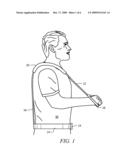
[0010]FIG. 1 illustrates a side view of a device of the present invention being worn by a user.
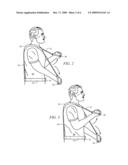
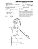
[0011]FIG. 2 illustrates a side view of a device of the present invention in use.
[0012]FIG. 3 illustrates a second side view of a device of the present invention in use.
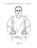
[0013]FIG. 4 illustrates a front view of a device of the present invention in use.
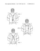
[0014]FIG. 5 illustrates a rear view of a first embodiment of a device of the present invention being worn by a user.
[0015]FIG. 6 illustrates a rear view of a second embodiment of a device of the present invention being worn by a user.
[0016]FIG. 7 illustrates a rear view of a third embodiment of a device of the present invention being worn by a user.
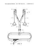
[0017]FIG. 8 illustrates a perspective view of the first embodiment of a device of the present invention.
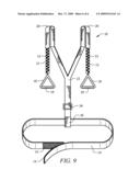
[0018]FIG. 9 illustrates a perspective view of a fifth embodiment of a device of the present invention.
DETAILED DESCRIPTION OF THE INVENTION
[0019]Reference will now be made in detail to the presently preferred embodiments of the invention, examples of which are illustrated in the accompanying drawings. Throughout the following detailed description, the same reference numerals refer to the same elements in all figures.
[0020]Referring to FIG. 1, a side view of a device of the present invention being worn by a user is shown. The device includes a belt 14 to be worn around the user's mid section or waist. In the preferred embodiment, the belt 14 is part of the exercise device while in alternate embodiments, the belt 14 is any belt available to the user and the exercise device attaches to the belt 14 provided by the user in ways known in the industry. The belt 14 is joined and tightened around the user by a buckle 15 or any other way known in the industry.
[0021]One or more straps 16 are attached to the belt 14. In a preferred embodiment, the user's 50 shoulders are cushioned by a shoulder cushion 20 beneath or around the straps 16 to improve comfort to the user 50.
[0022]Top ends of the straps 16 are attached to resilient members 12. In this example, the resilient members 12 are stretchable materials such as elastic members (e.g., surgical tubing, etc) while in other embodiments, the resilient members 12 are springs. Distal ends of the resilient members 12 attach to handles 18 which is shown, for example, as a stirrup-type handle while any suitable handle is anticipated.
[0023]Referring to FIG. 2 and 3, a side view of a device of the present invention in use is shown. The belt 14 is worn around the user's mid section or waist and the one or more straps 16 are attached to the belt 14 and passed over the user's 50 shoulders where they are attached to the resilient members 12 and the resilient members attached to handles 18. The optional shoulder cushion 20 improves comfort to the user as the user 50 pushes downward or outward with their right hand (as in FIG. 2) and then pushes downward or outward with their left hand (as in FIG. 3).
[0024]Referring to FIG. 4, a front view of a device of the present invention in use is shown. In this view, one typical belt buckle 15 is shown and the user 50 is grasping both handles 18 and pushing down. In this example, the resilient members 12 are stretchable materials such as elastic members (e.g., surgical tubing, etc) while in other embodiments, the resilient members 12 are springs. The optional shoulder cushion 20 provides improved comfort to the user as the user 50 pushes downward or outward with their right hand (as in FIG. 2) and then pushes downward or outward with their left hand (as in FIG. 3).
[0025]Referring to FIG. 5, a rear view of a first embodiment of a device of the present invention being worn by a user is shown. In this embodiment, the back strap 16 is in the form of a single strap 16 that forms a "Y" 22 with a bottom end and two top ends, the top ends passing through or over the two shoulder cushions 20. Various back configurations are anticipated, all of which are included here within. In this embodiment, a tightening mechanism 24 is provided to adjust the length of the bottom end of the back strap 16 to conform to various user heights.
[0026]Referring to FIG. 6, a rear view of a second embodiment of a device of the present invention being worn by a user is shown. In this embodiment, the back strap is in the form of two parallel straps 32 that connect to each other by a horizontal strap 30. The ends of the two straps 32 continue through or over the two cushions 20. Various back configurations are anticipated, all of which are included here within.
[0027]Referring to FIG. 7, a rear view of a third embodiment of a device of the present invention being worn by a user is shown. In this embodiment, the back strap is in the form of two crossed straps 42 that connect to each other at a bonding point 40. The ends of the two straps 42 continue through the two shoulder cushions 20. The straps are affixed to the belt 14 in ways known in the industry including, but not limited to, stitching directly to the belt 14 or looping around the belt 14 and stitching back upon itself.
[0028]Referring to FIG. 8, a perspective view of the first embodiment of a device of the present invention is shown. The device includes a belt 14 and a belt fastener 15. In this embodiment, the belt fastener is hook and loop material 15 although in other embodiments other types of belt fasteners such as buckles, button/eyes and the like are anticipated. In this embodiment, one strap 16 is attached to the belt 14, although in other embodiments two or more straps are anticipated as previously described. As an example, the strap 16 is attached to the belt 14 by a loop 26 formed in the end of the strap 16, the loop 26 passing around the belt 14 then affixed back upon the strap 16 as known in the industry.
[0029]In this example, the straps 16 form a Y 22 and the top sections of the straps 22 pass through or over optional shoulder cushions 20 to improve comfort to the user. In some embodiments, the shoulder cushions 20 are affixed to a bottom surface of the top sections of the straps 16 by, for example, stitching, gluing, bonding, etc. It is preferred that the shoulder cushions 20 include a soft material situated between the top section of the straps 22, thereby providing cushioning to the user's shoulders. Each strap is attach to a first end of a resilient member 12 and the other end of the resilient member 12 is attached to a handle 18 which is shown as a stirrup-type handle while any suitable handle is anticipated. In this embodiment, the resilient member 12 is a stretchable material such as rubber or fabric impregnated with rubber threads, etc. One example of such material is surgical rubber tubing. In this example, the handle 18 has an optional grip 19.
[0030]Referring to FIG. 9, a perspective view of a fifth embodiment of a device of the present invention is shown. As in FIG. 8, the device includes a belt 14 and a belt fastener 15. In this embodiment, the belt fastener is hook and loop material 15 although in other embodiments other types of belt fasteners such as buckles, button/eyes and the like are anticipated. In this embodiment, one strap 16 is attached to the belt 14, although in other embodiments two or more straps are anticipated as previously described. As an example, the strap 16 is attached to the belt 14 by a loop 26 formed in the end of the strap 16, the loop 26 passing around the belt 14 then affixed back upon the strap 16 as known in the industry.
[0031]The straps 16 form a Y 22 and the top sections of the straps 22 pass through or over optional shoulder cushions 20 to improve comfort to the user. In some embodiments, the shoulder cushions 20 are affixed to a bottom surface of the top sections of the straps 16 by, for example, stitching, gluing, bonding, etc. It is preferred that the shoulder cushions 20 include a soft material situated between the top section of the straps 22, thereby providing cushioning to the user's shoulders. Each strap is attach to a first end of a resilient member 13 and the other end of the resilient member 13 is attached to a handle 18 which is shown as a stirrup-type handle while any suitable handle is anticipated. In this embodiment, the resilient member 13 is a spring 13. Any known spring technology is anticipated, preferably a coil spring. The spring 13 is made from any spring material such as spring steel and spring plastic. It is preferred, though not required, to cover the springs 13 with a sleeve 15 to prevent pinching when the springs 13 are retracted. The sleeves 15 are made from any suitable material such as cloth and, preferable, expands when the springs 13 are extended. In some embodiments, the sleeves 15 are gathered or accordion style, providing for expansion as the springs 13 are extended. In this example, the handle 18 has an optional grip 19.
[0032]Equivalent elements can be substituted for the ones set forth above such that they perform in substantially the same manner in substantially the same way for achieving substantially the same result.
[0033]It is believed that the system and method of the present invention and many of its attendant advantages will be understood by the foregoing description. It is also believed that it will be apparent that various changes may be made in the form, construction and arrangement of the components thereof without departing from the scope and spirit of the invention or without sacrificing all of its material advantages. The form herein before described being merely exemplary and explanatory embodiment thereof. It is the intention of the following claims to encompass and include such changes.
User Contributions:
comments("1"); ?> comment_form("1"); ?>Inventors list |
Agents list |
Assignees list |
List by place |
Classification tree browser |
Top 100 Inventors |
Top 100 Agents |
Top 100 Assignees |
Usenet FAQ Index |
Documents |
Other FAQs |
User Contributions:
Comment about this patent or add new information about this topic:
Images included with this patent application:
 |  |
 |  |
 |  |
 |
| New patent applications in this class: | |
| Date | Title |
|---|---|
| 2019-05-16 | Resistance training system |
| 2019-05-16 | Fitness training apparatus |
| 2017-08-17 | Elastic member and garment incorporating same |
| 2016-06-16 | Lower extremity receiving device for providing enhanced leg mobility during lower body exercise |
| 2016-06-16 | Antigravity whole body exercise garments |
| Top Inventors for class "Exercise devices" | |
| Rank | Inventor's name |
|---|---|
| 1 | William T. Dalebout |
| 2 | Scott R. Watterson |
| 3 | Raymond Giannelli |
| 4 | Leao Wang |
| 5 | Bruce Hockridge |