Patent application title: Magnaforce generator
Inventors:
Stephen Calanari Sayre (Taft, CA, US)
Garrett Stewart Sayre (Yorktown, VA, US)
IPC8 Class: AF03G700FI
USPC Class:
290 1 R
Class name: Prime-mover dynamo plants miscellaneous
Publication date: 2009-12-17
Patent application number: 20090309372
Inventors list |
Agents list |
Assignees list |
List by place |
Classification tree browser |
Top 100 Inventors |
Top 100 Agents |
Top 100 Assignees |
Usenet FAQ Index |
Documents |
Other FAQs |
Patent application title: Magnaforce generator
Inventors:
Stephen Calanari Sayre
Garrett Stewart Sayre
Agents:
Garrett S. Sayre
Assignees:
Origin: YORKTOWN, VA US
IPC8 Class: AF03G700FI
USPC Class:
290 1 R
Patent application number: 20090309372
Abstract:
The MagnaForce Generator is an energy producing device using magnetic
force in a way that allows continuous movement to produce energy. The
device described above where one or more of the magnets are attached to a
device which moves the magnet(s) to maximize the free flow of the
movement created by the magnetic fields. Most likely magnets in a circle
with a spinning magnet on a shaft in the middle The device described
incorporates piston(s) which retreats into a cylinder to avoid opposing
forces from or related to the primary rotational device that do not
complement the production of energy and that emerge to assist in the
production. The device incorporates materials that redirect the magnetic
fields to maximize the production of energy. The device described might
incorporate any pre-existing braking device. The device described might
incorporate a pre-existing generating device. The device described might
incorporate a locomotive device.Claims:
1. Permanent magnets arranged in such a way that it allows continuous
movement to produce energy.
2. The device described in claim 1 where one or more of the magnets are attached to device which moves the magnet(s) to maximize the free flow of the movement created by the magnetic fields.
3. The device described in claims 1 and 2 which incorporates a piston to maximize the production of energy.
4. The device described in claims 1, 2, and 3 which incorporates materials that redirect the magnetic fields to maximize the production of energy.
5. The device described in claims 1 and 2 which incorporates materials that redirect the magnetic fields to maximize the production of energy.
6. The device described in claims 1-5 that incorporates any pre-existing braking device.
7. The device described in claims 1-5 that incorporates any pre-existing generating device.
8. The device described in claims 1-5 that incorporates any locomotive device.
9. The device described in claims 1-5 that incorporates any number of pistons or other devices described in claims 1-8.
Description:
FIELD OF INVENTION
[0001]This invention relates to the production of continuous movement using magnetic force for the production of energy.
BACKGROUND OF THE INVENTION
[0002]The MagnaForce Generator is designed to use magnetic force to produce energy by using a system of directing and redirecting magnetic energy.
SUMMARY OF INVENTION
[0003]The objective of this invention is to produce energy using permanent magnets in a system of directing and redirecting magnetic force. [0004]The objective of this device is permanent magnets arranged in such a way that it allows continuous movement to produce energy. [0005]The objective of the device where one or more of the magnets are attached to device which moves the magnet(s) to maximize the free flow of the movement created by the magnetic fields. [0006]The objective of the device to incorporate a piston to maximize the production of energy. [0007]The objective of the device to incorporate materials that redirect the magnetic fields to maximize the production of energy. [0008]The objective of the device to incorporate materials that redirect the magnetic fields to maximize the production of energy. [0009]The objective of the device to incorporate any pre-existing braking device. [0010]The objective of the device to incorporate any pre-existing generating device. [0011]The objective of the device to incorporate any locomotive device. [0012]The objective of the device that incorporates any number of pistons or other devices.
BRIEF DESCRIPTION OF SEVERAL VIEWS OF THE DRAWING
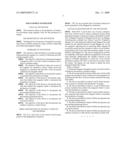
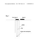
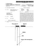
[0013]FIG. 1 is a side view of one section of power generation of the Magnaforce Generator.
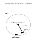
[0014]FIG. 2 is an over head view of a primary function in power generation of the Magnaforce Generator.
DETAILED DESCRIPTION OF THE INVENTION
[0015]Both FIGS. 1 and 2 show one of many configurations that could be used to obtain continuous motion using permanent magnets to generate energy as described in claims 1-9. As Magnet #1 passes by Magnet #2 (see FIG. 2), Magnet #2 retreats into a cylinder via a "piston" (see FIG. 1) linked to Magnet #1 so that during the optimal time Magnet #2 would extend into the optimal position to push Magnet #1 via the two magnets' opposing and /or attracting fields. Magnet #2 would also retreat into the cylinder in order to avoid conflicting polarities and at the same time generate energy in combination with Magnet #1. The above configuration could be accomplished with many different arrangements of the same basic principal. Additionally, the cylinder could be of any shape or workable dimension as could any of the devices described in claims 1-9. FIGS. 1 and 2 are not meant to limit the claims. The figures are only meant to depict the basic principal behind the Claims.
User Contributions:
comments("1"); ?> comment_form("1"); ?>Inventors list |
Agents list |
Assignees list |
List by place |
Classification tree browser |
Top 100 Inventors |
Top 100 Agents |
Top 100 Assignees |
Usenet FAQ Index |
Documents |
Other FAQs |
User Contributions:
Comment about this patent or add new information about this topic:
Images included with this patent application:
 |  |
 |  |
| Similar patent applications: | |
| Date | Title |
|---|---|
| 2010-07-15 | Two-stage cooling fan for an electric generator |
| 2008-12-18 | Methods and apparatus for power generation |
| 2009-03-05 | Magnus force fluid flow energy harvester |
| 2010-03-04 | Magnetically geared generator |
| 2010-05-13 | Methods and apparatus for power generation |
| New patent applications in this class: | |
| Date | Title |
|---|---|
| 2018-01-25 | Gravity-lever-actuated rotating engine |
| 2016-12-29 | Transient absorber for power generation system |
| 2016-07-07 | Power generation apparatus |
| 2016-07-07 | Modular power generator |
| 2016-05-26 | Buoyancy-driven power generation system |
| Top Inventors for class "Prime-mover dynamo plants" | |
| Rank | Inventor's name |
|---|---|
| 1 | Henrik Stiesdal |
| 2 | Per Egedal |
| 3 | Akira Yasugi |
| 4 | Takatoshi Matsushita |
| 5 | Lowell L. Wood, Jr. |