Patent application title: EXHAUST-GAS PURIFICATION APPARATUS AND METHOD FOR PURIFYING EXHAUST GAS
Inventors:
Tatsuya Fujita (Obu-City, JP)
Masatoshi Maruyama (Nagoya-City, JP)
Assignees:
DENSO CORPORATION
NIPPON SOKEN, INC.
IPC8 Class: AF01N900FI
USPC Class:
60286
Class name: Internal combustion engine with treatment or handling of exhaust gas by means producing a chemical reaction of a component of the exhaust gas condition responsive control of heater, cooler, igniter, or fuel supply of reactor
Publication date: 2009-12-10
Patent application number: 20090301068
Inventors list |
Agents list |
Assignees list |
List by place |
Classification tree browser |
Top 100 Inventors |
Top 100 Agents |
Top 100 Assignees |
Usenet FAQ Index |
Documents |
Other FAQs |
Patent application title: EXHAUST-GAS PURIFICATION APPARATUS AND METHOD FOR PURIFYING EXHAUST GAS
Inventors:
Tatsuya Fujita
Masatoshi Maruyama
Agents:
NIXON & VANDERHYE, PC
Assignees:
DENSO CORPORATION
Origin: ARLINGTON, VA US
IPC8 Class: AF01N900FI
USPC Class:
60286
Patent application number: 20090301068
Abstract:
A NOx catalyst is provided in an exhaust passage of an internal combustion
engine for selectively purifying NOx in exhaust gas with a reducing
agent. A charging unit charges the reducing agent at an upstream of the
NOx catalyst. A pressurizing unit supplies the reducing agent to the
charging unit. An obtaining unit detects or estimates catalyst
temperature of the NOx catalyst or temperature information, which is
correlated with the catalyst temperature. A particle size control unit
changes reducing-agent pressure of reducing agent, which is pressurized
by the pressurizing unit and supplied to the charging unit, to control an
atomized particle size of the reducing agent, which is atomized from the
charging unit and charged into exhaust gas, based on the catalyst
temperature or the temperature information.Claims:
1. An exhaust-gas purification apparatus for an exhaust-gas-purification
system for an internal combustion engine, the system including a NOx
catalyst, which is provided in an exhaust passage of the internal
combustion engine for selectively purifying NOx in exhaust gas with a
reducing agent, charging means, which is for charging the reducing agent
into exhaust gas at an upstream of the NOx catalyst, and pressurizing
means, which is for pressurizing the reducing agent and supplying the
reducing agent to the charging means, the exhaust-gas purification
apparatus comprising:obtaining means for detecting or estimating catalyst
temperature of the NOx catalyst or temperature information, which is
correlated with the catalyst temperature; andparticle size control means
for changing reducing-agent pressure of reducing agent, which is
pressurized by the pressurizing means and supplied to the charging means,
to control an atomized particle size of the reducing agent, which is
atomized from the charging means and charged into exhaust gas, based on
the catalyst temperature or the temperature information.
2. The exhaust-gas purification apparatus according to claim 1, wherein the particle size control means controls the pressurizing means to increase the reducing-agent pressure when the catalyst temperature is in a low-temperature range.
3. The exhaust-gas purification apparatus according to claim 2,wherein the particle size control means is configured to control a particle diameter of the reducing agent at a large size and a small size, andthe low-temperature range is less than a temperature threshold, at which a purification rate of the NOx catalyst is saturated when the particle size control means controls the particle diameter at the large size.
4. The exhaust-gas purification apparatus according to claim 1, wherein the particle size control means is configured to decrease the atomized particle size in an start operation of the internal combustion engine and configured to increase the atomized particle size after elapsing a predetermined period subsequent to the start operation.
5. The exhaust-gas purification apparatus according to claim 4, further comprising:heating means for heating the reducing agent charged by the charging means,wherein the particle size control means is configured to control the heating means to heat the reducing agent to change the atomized particle size, in addition to pressurization of the reducing agent by the pressurizing means.
6. The exhaust-gas purification apparatus according to claim 1, further comprising:means for detecting the reducing-agent pressure; andmeans for manipulating at least one of a cycle, at which the charging means charges the reducing agent, and a charge time of urea water for each injection, based on the detected reducing-agent pressure.
7. A method for purifying exhaust gas of an internal combustion engine, the method comprising:detecting or estimating catalyst temperature of a NOx catalyst, which is provided in an exhaust passage of the internal combustion engine for selectively purifying NOx in exhaust gas with a reducing agent, or temperature information, which is correlated with the catalyst temperature; andmanipulating reducing-agent pressure of reducing agent, which is charged into exhaust gas at an upstream of the NOx catalyst, to control an atomized particle size of the reducing agent based on the catalyst temperature or the temperature information.
8. The method according to claim 7,wherein the manipulating further includes:increasing the reducing-agent pressure when the catalyst temperature is in a low-temperature range.
9. The method according to claim 8,wherein the manipulating further includes:controlling a particle diameter of the reducing agent at a large size and a small size,wherein the low-temperature range is less than a temperature threshold, at which a purification rate of the NOx catalyst is saturated when the particle diameter is controlled at the large size.
10. The method according to claim 7wherein the manipulating further includes:decreasing the atomized particle size in an start operation of the internal combustion engine; andincreasing the atomized particle size after elapsing a predetermined period subsequent to the start operation.
11. The method according to claim 10, further comprising:heating the reducing agent to change the atomized particle size, in addition to pressurization of the reducing agent by the pressurizing means.
12. The method according to claim 7, further comprising:detecting the reducing-agent pressure; andmanipulating at least one of a cycle, at which the charging means charges the reducing agent, and a charge time of urea water for each injection, based on the detected reducing-agent pressure.
Description:
CROSS REFERENCE TO RELATED APPLICATIONS
[0001]This application is based on and incorporates herein by reference Japanese Patent Application No. 2008-147854 filed on Jun. 5, 2008.
FIELD OF THE INVENTION
[0002]The present invention relates to an exhaust-gas purification apparatus for an exhaust gas purification system such as a selective catalytic reduction (SCR) system having a selective reduction catalyst for selectively purifying nitrogen oxide (NOx) in exhaust gas of an internal combustion engine by charging ammonia as a reducing agent. The present SCR system generally employs a urea aqueous solution as a reducing agent, and such an SCR system is known as a urea SCR system. The present invention relates to a method for purifying exhaust gas of the internal combustion engine.
BACKGROUND OF THE INVENTION
[0003]In recent years, development of a urea SCR system is in progress and partially in practical use. Such a urea SCR system is employed as an exhaust-gas-purification system for an engine such as a diesel engine for a vehicle such as an automobile so as to purify NOx in exhaust gas of at a high purification rate. A conventional urea SCR system has the following structure. In a urea SCR system, a selective reduction type NOx catalyst is provided in an exhaust pipe, which is connected to a main body of an engine. A urea water charge valve is further provided in the exhaust pipe at an upstream of the NOx catalyst for charging urea water (urea aqueous solution) as a NOx reducing agent. In the urea SCR system, the urea water charge valve charges urea water into the exhaust pipe so as to selectively perform reductive reaction and removal of NOx, which is contained in exhaust gas, on the NOx catalyst. In the reductive reaction of NOx, urea water is hydrolyzed by thermal energy of exhaust-gas to produce ammonia (NH3), and thereby the ammonia is absorbed into the NOx catalyst to cause reductive reaction on the NOx catalyst. Thereby, NOx is deoxidized and purified.
[0004]Furthermore, for example, JP-A-2007-255343 proposes an art to accelerate evaporation and diffusion of a reducing agent, which is charged from a urea water charge valve into an exhaust pipe, so as to enhance a NOx purification performance of a NOx catalyst. Specifically, in JP-A-2007-255343, a shielding member is provided in the exhaust passage at an upstream of the NOx catalyst in an exhaust-gas flow, and a depurator is injected to a downstream of the shielding member so as to accelerate atomization of the depurator. In the present structure, the depurator injected into the exhaust passage collides with the distribution member, and thereby further atomized. However, in JP-A-2007-255343, the shielding member and the distribution member increase pressure loss in the exhaust passage. The pressure loss in the exhaust passage is regularly caused during an operation of the engine, and consequently the engine is exerted with an adverse effect such as increase in fuel consumption. The exhaust-gas flow varies in response to an operation state of the engine. For example, an amount of intake air and exhaust gas increases when the engine is in a high load operation state. In such a high load operation state, pressure loss caused by the shielding member and the distribution member in the exhaust passage becomes large, and consequently fuel consumption is increased.
SUMMARY OF THE INVENTION
[0005]In view of the foregoing and other problems, it is an object of the present invention to produce an exhaust-gas-purification apparatus for controlling a reducing agent charged to enhance a NOx purification rate of an internal combustion engine and configured to restrict an adverse influence to the internal combustion engine. It is another object of the present invention to produce a method for purifying exhaust gas of the internal combustion engine.
[0006]According to one aspect of the present invention, an exhaust-gas purification apparatus for an exhaust-gas-purification system for an internal combustion engine, the system including a NOx catalyst, which is provided in an exhaust passage of the internal combustion engine for selectively purifying NOx in exhaust gas with a reducing agent, charging means, which is for charging the reducing agent into exhaust gas at an upstream of the NOx catalyst, and pressurizing means, which is for pressurizing the reducing agent and supplying the reducing agent to the charging means, the exhaust-gas purification apparatus comprises obtaining means for detecting or estimating catalyst temperature of the NOx catalyst or temperature information, which is correlated with the catalyst temperature. The exhaust-gas purification apparatus further comprises particle size control means for changing reducing-agent pressure of reducing agent, which is pressurized by the pressurizing means and supplied to the charging means, to control an atomized particle size of the reducing agent, which is atomized from the charging means and charged into exhaust gas, based on the catalyst temperature or the temperature information.
[0007]According to another aspect of the present invention, a method for purifying exhaust gas of an internal combustion engine, the method comprises detecting or estimating catalyst temperature of a NOx catalyst, which is provided in an exhaust passage of the internal combustion engine for selectively purifying NOx in exhaust gas with a reducing agent, or temperature information, which is correlated with the catalyst temperature. The method further comprises manipulating reducing-agent pressure of reducing agent, which is charged into exhaust gas at an upstream of the NOx catalyst, to control an atomized particle size of the reducing agent based on the catalyst temperature or the temperature information.
BRIEF DESCRIPTION OF THE DRAWINGS
[0008]The above and other objects, features and advantages of the present invention will become more apparent from the following detailed description made with reference to the accompanying drawings. In the drawings:
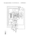
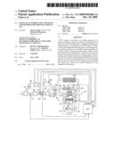
[0009]FIG. 1 is an over view showing an engine control system according to an embodiment of the present invention;
[0010]FIG. 2 is a graph showing a relationship between a NOx purification rate of an SCR catalyst, an SCR catalyst temperature, and an atomized particle size of urea water;
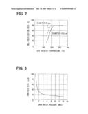
[0011]FIG. 3 is a graph showing a relationship between a urea water pressure and the atomized particle size of urea water;
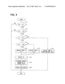
[0012]FIG. 4 is a flow chart showing a urea water charge control;
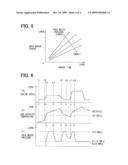
[0013]FIG. 5 is a graph showing a relationship between an amount of urea water charge, the urea water pressure, and an opening period of a urea water charge valve, and
[0014]FIG. 6 is a time chart showing the urea water control.
DETAILED DESCRIPTION OF PREFERRED EMBODIMENTS
Embodiment
[0015]As follows, an embodiment of the present invention will be described with reference to drawings. In the present embodiment, an engine control system controls a multi-cylinder diesel engine for a vehicle as a controlled object. In the control system, an electronic control unit (ECU) performs various control operations of the engine. In the present embodiment, a common-rail fuel injection system is employed as a fuel injection system, and a urea SCR system is employed as an exhaust-gas-purification system. First, an entire system will be described with reference to FIG. 1. An engine 10 includes an engine main body 11, which has a reciprocating engine structure. A piston 12 is movable back and forth in a cylinder of the engine main body 11. An intake valve 13 and an exhaust valve 14 are respectively and correspondingly provided to an intake port and an exhaust port for opening and closing the intake port and the exhaust port. A crankshaft 15 is rotatable in response to the movement of the piston 12. A fuel injection valve 16 is provided for each cylinder in the cylinder head. The fuel injection valve 16 directly injects fuel into a combustion chamber 17, and the injected fuel is burned in the combustion chamber 17. A crank angle sensor 18 is provided to the crankshaft 15 for detecting rotation of the crankshaft 15. A temperature sensor 19 is provided to the cylinder block for detecting temperature of engine cooling water.
[0016]As follows, a structure of a fueling system will be briefly described. The fueling system may have a generally known structure, and therefore detailed description of the fueling system with reference to drawings is omitted. For example, the fueling system includes a high-pressure pump and a common rail (accumulator pipe). The high-pressure pump pressurizes fuel drawn from a fuel tank and press-feeds the pressurized fuel to a common rail. The common rail accumulates high-pressure fuel of several tens to two hundred MPa, and the accumulated high-pressure fuel is supplied to the fuel injection valve 16 of each cylinder. Fuel pressure in the common rail is arbitrarily controlled according to an engine operation state and the like. An intake pipe 21 including a manifold portion is connected to the intake port of the engine main body 11, and an exhaust pipe 22 including a manifold portion is connected to the exhaust port. A throttle actuator 23, which has an electric throttle valve, is provided in the intake pipe 21. An EGR passage 24 connects an intake passage in the intake pipe 21 with an exhaust passage in the exhaust pipe 22. An EGR valve 25 and an EGR cooler 26 are provided in the EGR passage 24. An air cleaner 27 is provided at the uppermost in the intake pipe 21. Air flow meter (intake air sensor) 28 is provided in the air cleaner 27. A turbocharger 30 is provided as a supercharging device in the furling system. The turbocharger 30 includes an air intake compressor 31, which is provided in the intake pipe 21, and an exhaust turbine 32, which is provided in the exhaust pipe 22. The exhaust turbine 32 is driven by exhaust gas flowing through the exhaust pipe 22 to produce torque, and the torque is transmitted via a shaft 33 to the air intake compressor 31. Thus, the air intake compressor 31 pressurizes intake air flowing through the intake pipe 21, thereby to supercharge the intake air. The intake air supercharged by the turbocharger 30 is cooled through an intercooler 34, and thereafter fed to the downstream of the intake pipe 21. The intake pipe 21 is further provided with sensors such as an intake air pressure sensor and an intake air temperature sensor.
[0017]Next, the exhaust-gas-purification system of the exhaust system will be described in further detail. In the exhaust pipe 22, an oxidation catalyst 41, a selective catalytic reduction (SCR) catalyst (ammonia selective reduction catalyst) 42, and an ammonia slip catalyst 43 are sequentially provided from the upstream. The SCR catalyst 42 is equivalent to a NOx catalyst. A urea water charge valve 44 is provided between the oxidation catalyst 41 and the SCR catalyst 42 in the exhaust pipe 22 for charging urea water (urea aqueous solution) as a reducing agent into the exhaust pipe 22. The urea water charge valve 44 has substantially the same structure as a generally known fuel injection valve (injector) actuated by an electromagnetic power source such as a solenoid. The urea water charge valve 44 opens in response to an electric control instruction, and thereby injecting urea water from a tip end nozzle hole portion of the urea water charge valve 44. The urea water charge valve 44 is successively supplied with urea water from a urea water tank 51. Next, the structure of a urea water charge system will be described in detail. The urea water tank 51 is an airtight container provided with a liquid supply cap. The urea water tank 51 stores urea water of predetermined concentration such as 32.5%. The urea water tank 51 is connected with one end of a urea water piping 52. A urea water pump 53 is provided as a compression unit midway through the urea water piping 52. The other end of the urea water piping 52 is connected to the urea water charge valve 44. Similarly, a pressure sensor 54 is provided in the urea water piping 52 for detecting pressure of urea water in the urea water piping 52. The urea water pump 53 is an electromotive pump and driven in response to a driving signal transmitted from an ECU 60. The urea water pump 53 is driven so as to pump urea water from the urea water tank 51 to the urea water charge valve 44 through the urea water piping 52. In the present embodiment, it is noted that the urea water pump 53 is variable in feeding capacity (press-feeding amount) of urea water. Thus, the urea water piping 52 is capable of manipulating feed pressure of urea water in response to change in the feeding capacity. The urea water pump 53 may be an in-tank pump immersed in urea water inside the urea water tank 51. A mixer 55 is provided between the oxidation catalyst 41 and the SCR catalyst 42 in the exhaust pipe 22 for causing swirl flow in exhaust gas flowing through the exhaust pipe 22. The mixer 55 is an exhaust-gas stirring device, which includes a rotor having multiple vane pieces, for example. The mixer 55 rotates in response to passage of exhaust gas, and thereby swirls exhaust gas flowing into the SCR catalyst 42.
[0018]In the present exhaust-gas-purification system, urea water is charged from the urea water charge valve 44 into the exhaust pipe 22 in the engine operation, and thereby urea water is charged together with exhaust gas into the SCR catalyst 42 in the exhaust pipe 22. Thus, NOx causes reductive reaction in the SCR catalyst 42, and thereby exhaust gas is purified. Specifically, urea water injected from the urea water charge valve 44 is applied with thermal energy of exhaust-gas and thereby to cause the following reaction (1) and hydrolyzed to produce ammonia (NH3).
((NH2)2CO)+H2O→2NH3+CO2 (1)
[0019]As exhaust gas passes through the SCR catalyst 42, the charged ammonia selectively causes reduction reaction and purification in NOx in the exhaust gas. In the present reductive reaction and purification of NOx, the following reduction reactions (2) to (3) are caused.
4NO+4NH3+O2→4N2+6H2O (2)
6NO2+8NH3→7N2+12H2O (3)
NO+NO2+2NH3→2N2+3H2O (4)
[0020]In the present reductive reaction and purification of NOx caused by ammonia, ammonia may be excessive, and surplus ammonia may not cause reaction with NOx. In this case, the surplus ammonia is mixed with exhaust gas and emitted downstream of the exhaust gas flow. The surplus ammonia is to be removed by the ammonia slip catalyst 43 at the downstream of the SCR catalyst. For example, the ammonia slip catalyst 43 may be an oxidation catalyst. An oxygen concentration sensor 45 and a temperature sensor 46 are further provided between the oxidation catalyst 41 and the SCR catalyst 42 in the exhaust pipe 22. The oxygen concentration in exhaust gas and the catalyst temperature are detected based on an output signal of the sensors 45, 46. A NOx sensor 47 is provided at the downstream of the SCR catalyst 42 so as to detect an amount of NOx, which relates to the NOx concentration in exhaust gas after passing through the SCR catalyst 42. A NOx purification rate of the SCR catalyst 42 is detected based on an output signal of the NOx sensor 47. In FIG. 1, a diesel particulate filter (DPF not shown) is provided in the exhaust pipe 22 for capturing particulate matter (PM) in exhaust gas.
[0021]The ECU 60 includes a generally-known microcomputer (not shown) having a CPU, a ROM, a RAM, and the like. The ECU 60 receives the detection signals of a rail pressure sensor, which is for detecting fuel pressure (rail pressure) in the common rail, and an accelerator sensor, which is for detecting manipulation of an accelerator pedal (accelerator position), and the like, in addition to the detection signals of the various sensors. Thereby, the ECU 60 performs a fuel injection control, a fuel pressure control (rail pressure control), and the like based on engine operation information items including an engine speed, the accelerator position, and the like. In the present structure, an injection operation of the fuel injection valve 16 and a feeding operation of a high-pressure pump are controlled. In addition, the ECU 60 arbitrarily controls the throttle actuator 23, the EGR valve 25, and the like, based on the engine operation state. The ECU 60 calculates an amount of NOx at the downstream of the SCR catalyst 42 and a NOx purification rate based on the output signal of the NOx sensor 47. The ECU 60 further controls an amount of urea water to be charged based on the NOx purification rate. The NOx purification rate X1 is calculated based on an amount of NOx (Y1) emitted from the engine and an amount NOx (Y2) at the downstream of the SCR catalyst 42 by using the following calculation of (X1=(Y1-Y2)/Y1). The amount of NOx (Y1) emitted from the engine is calculated by using an equation or obtained from a data map based on an engine operation state such as an engine speed and fuel an injection quantity of each time. The amount NOx (Y2) at the downstream of the SCR catalyst 42 is calculated based on the output signal of the NOx sensor 47.
[0022]It is noted that an amount of ammonia adsorption of the SCR catalyst 42 may be calculated, and an amount of urea water to be charged may be controlled based on the amount of ammonia adsorption. Specifically, an actual amount of ammonia adsorption (actual adsorption) may be calculated based on a balance of charge of ammonia and consumption of ammonia, which is caused by reaction in the SCR catalyst 42. Further, the amount of urea water to be charged may be feedback-controlled based on a deviation between the actual adsorption and a target value.
[0023]As follows, an operation of the urea water charge valve 44 will be described in detail. The ECU 60 outputs an open command pulses to the urea water charge valve 44 at a predetermined cycle. Thereby, a driving current flows in an actuator portion (solenoid portion) of the urea water charge valve 44 in response to the open command pulses. Thus, the urea water charge valve 44 is opened in response to the driving current, and thereby urea water is injected and charged. In the present condition, the amount of urea water to be charged (urea water charge) is controlled by manipulating an output cycle or an output frequency of the open command pulses. Specifically, the output cycle of the open command pulses is increased so as to decrease the urea water charge. Alternatively, the output cycle of the open command pulses is decreased so as to increase the urea waters charge. The driving current of the urea water charge valve 44 may be terminated for a predetermined time period so as to decrease the urea water charge.
[0024]It is noted that the NOx purification rate of the SCR catalyst 42, the SCR catalyst temperature, and an atomized particle size of urea water have a correlation thereamong. For example, the inventor of the present invention investigated the correlation shown in FIG. 2 by conducting experiments. FIG. 2 is a graph showing the correlation between the SCR catalyst temperature and the NOx purification rate in the case where the atomized particle size of urea water is changed. In FIG. 2, the solid line indicates the case where the atomized particle size is 100 micrometers in a normal operation of the pump, and the two-dot chain line indicates the case where the atomized particle size is 20 micrometers and reduced to produce further microscopic spray than the normal operation.
[0025]FIG. 2 indicates that when the SCR catalyst temperature is higher than 220° C., the NOx purification rate is saturated at a predetermined high purification rate of about 80%, and the NOx purification performance is substantially constant regardless of the atomized particle size. Alternatively, when the SCR catalyst temperature is lower than 220° C., the NOx purification performance is excellent in the condition where the atomized particle size is small. It is conceived that when the temperature of the SCR catalyst 42 is low, urea water spray, which is smaller in the atomized particle size, is tend to obtain thermal energy from exhaust gas therearound, and thereby production of ammonia is accelerated. In the case where the particle diameter is 100 micrometer, the saturation temperature of the NOx purification rate is about 220° C., and in the case where the particle diameter is 20 micrometer, the saturation temperature of the NOx purification rate is about 200° C. That is, the NOx purification rate can be enhanced by using urea spraying of minute particle diameter in a low-temperature range equal to or less than the purification rate saturation temperature of about 220° C. when the particle diameter is 100 micrometers. It is noted that the NOx purification rate becomes 50% at an activated temperature of the SCR catalyst 42 in the normal charge of urea water of atomized particle size of 100 micrometers. In the present embodiment, the activated temperature of the SCR catalyst 42 is about 180° C.
[0026]For example, the pressure of urea water (urea water pressure) and the atomized particle size of urea water charged to the urea water charge valve 44 therebetween have a correlation shown in FIG. 3. FIG. 3 indicates that as the urea water pressure becomes large, the atomized particle size of urea water becomes small. Therefore, in the present embodiment, the amount of urea water press-feed from the urea water pump 53 is manipulated so as to change the urea water pressure, and thereby to control the atomized particle size of urea water. In the present embodiment, urea water is increased in pressure to be in a compressed state and charged when the SCR catalyst 42 is relatively low in temperature and activity. Alternatively, urea water is decreased in pressure to be in a non-compressed state and charged when the SCR catalyst 42 is relatively high in temperature and activity. In this manner, atomization of urea water spray is arbitrary controlled by manipulating the urea water pressure, and thereby the NOx purification performance is maintained at a high level. When the SCR catalyst 42 is in a predetermined high-temperature state, the NOx purification performance can be maintained at a high level, regardless of the atomized particle size of urea water and pressurization of urea water. It is noted that in the predetermined high-temperature state, the pump load can be reduced by decreasing the urea water pressure. Thereby, power consumption of an in-vehicle battery can be reduced.
[0027]FIG. 4 is a flow chart showing a procedure of a urea water charge control. The ECU 60 repeats the present urea water charge control operation at a predetermined cycle.
[0028]In FIG. 4, at step S11, it is determined whether an engine speed NE is currently greater than a predetermined value K1. The predetermined value K1 is a threshold for determining whether the engine 10 is an operation state. For example, the predetermined value K1 is 800 rpm. Subsequently, at step S12, it is determined whether an SCR catalyst temperature Tscr is greater than a predetermined value K2. The SCR catalyst temperature Tscr is calculated based on an output signal of the temperature sensor 46 at the upstream of the SCR catalyst 42. The predetermined value K2 is a temperature threshold for determining whether the SCR catalyst 42 is in a completely activated state or a non-activated state. For example, the predetermined value K2 is 180° C. In the present embodiment, the temperature of 180° C. is equivalent to the catalyst temperature at which the NOx purification rate of the SCR catalyst 42 becomes 50%.
[0029]When at least one of steps S11, S12 makes a negative determination, the present processing is terminated. Alternatively, when both steps S11, S12 make positive determinations, the present processing proceeds to the following step S13. At step S13, it is determined whether the urea water pressure Pn is currently greater than a predetermined value K3. The urea water pressure Pn is calculated based on the detection signal of the pressure sensor 54 provided in the urea water piping 52. The predetermined value K3 is a pressure threshold for determining whether urea water can be charged from the urea water charge valve 44. The predetermined value K3 is a minimum pressure at which urea water can be charged. For example, the predetermined value K3 is 0.4 MPa.
[0030]The present processing proceeds to step S14 on condition of Pn≦K3. Alternatively, the present processing proceeds to step S15 on condition of Pn>K3. At step S14, the urea water pump 53 is driven at a predetermined rotation speed. Specifically, the urea water pump 53 is driven so as to obtain the urea water pressure Pn greater than the minimum pressure at which urea water can be charged from the urea water charge valve 44.
[0031]At step S15, it is determined whether the SCR catalyst temperature Tscr is greater than a predetermined value K4. The predetermined value K4 is a temperature threshold for determining whether urea water spray is to be microscopically atomized. For example, the predetermined value K4 is 220° C. The predetermined value K4 is a purification rate saturation temperature when the atomized particle size is 100 micrometer (refer to FIG. 2).
[0032]The present processing proceeds to step S16 on condition of Tscr>K4. Alternatively, the present processing proceeds to step S17 on condition of Tscr≦K4. At step S16, the first target pressure PT1 is set, and the urea water pump 53 is controlled based on the first target pressure PT1. At step S17, the second target pressure PT2 is set, and the urea water pump 53 is controlled based on the second target pressure PT2. The first target pressure PT1 is a normal urea water pressure. The first target pressure PT1 is, for example, 0.5 MPa. The second target pressure PT2 is higher than the first target pressure PT1. The second target pressure PT2 is, for example, 5 MPa. Under an assumption that the urea water pressure complies with the relation shown in FIG. 3, the atomized particle size is set at 100 micrometers by controlling the urea water pressure at the first target pressure PT1 (0.5 MPa), and the atomized particle size is set at 20 micrometers by controlling the urea water pressure at the second target pressure PT2 (5 MPa). The first target pressure PT1 is greater than the predetermined value K3 (0.4 MPa), which is the minimum pressure at which urea water can be charged.
[0033]Thereafter, at step S18, the urea water pressure is detected. At step S19, a control parameter of the urea water charge valve 44 is determined. Specifically, an opening period (charge time) of the urea water charge valve 44 in one injection is determined For example, the opening period is determined from the relationship shown in FIG. 5 with reference to the current amount of urea water charge and current urea water pressure. The amount of urea water charge is calculated based on the NOx purification rate or an amount of ammonia adsorption of each time. A charge cycle of urea water may be determined as a control parameter of the urea water charge valve 44 based on the current urea water pressure. A control parameter may be calculated based on the target pressure (PT1, PT2) of each time in place of the detection result of the urea water pressure.
[0034]Finally, at step S20, the urea water charge valve 44 charges urea water based on the control parameter determined at step S19.
[0035]FIG. 6 is a time chart for describing the urea water control further in detail according to the present embodiment. In FIG. 6, (a) shows a transition of the engine speed, (b) shows a transition of the SCR catalyst temperature, and (c) shows a transition of the urea water pressure. In FIG. 6, the engine 10 is started at the time point t1, and an idling operation is performed in the period between t1 and t2. Subsequent to the engine start operation, the SCR catalyst receives thermal energy from exhaust-gas, and thereby the SCR catalyst temperature gradually increases. Thereafter, at the time point t2, the engine speed increases in response to an operation such as acceleration, and thereby the SCR catalyst temperature starts quickly increasing. At the time point t3, the SCR catalyst temperature reaches the predetermined value K2 (180quadrature), and thereby the urea water pump 53 is operated so as to increase the urea water pressure. When the urea water pressure becomes greater than the predetermined value K3 (0.4 MPa), a control of the urea water pressure at the second target pressure PT2 (5 MPa) is started. Specifically, the urea water pressure is increased so as to microscopically atomize urea water and charge the atomized urea in the period between t3 and t4. Thereafter, when the SCR catalyst temperature reaches the predetermined value K4 (220quadrature) at the time point t4, the target value of the urea water pressure is changed from the second target pressure PT2 (5 MPa) to the first target pressure PT1 (0.5 MPa). In the present operation, the urea water pressure is changed to the normal pressure, and thereby normal spray of the urea water without the microscopic atomization is performed in the period between t4 and t5. Subsequently, the SCR catalyst temperature decreases with deceleration of the vehicle and becomes less than or equal to the predetermined value K4 (220quadrature) at the time point t5. At this time, the target value of the urea water pressure is again changed to the second target pressure PT2 (5 MPa), and thus, atomization of urea water spray is performed in the period between t5 and t8. In the period between t6 and t7, the SCR catalyst temperature becomes less than or equal to the predetermined value K2 (180quadrature), which is the activated temperature of the SCR catalyst 42. Therefore, in the period between t6 and t7, urea water charge is temporarily stopped, and the amount of urea water press-fed from the urea water pump 53 is decreased to be significantly small.
[0036]As described above, this embodiment produces the following operation effects. The pressure of urea water pumped from the urea water pump 53 is manipulated based on the SCR catalyst temperature of each time, and thereby the atomized particle size of urea water injected from the urea water charge valve 44 is controlled. In particular, when the SCR catalyst temperature is in the predetermined low-temperature range, the urea water pressure is increased so as to further microscopically atomize urea water and significantly decrease the particle size of urea water. In the present operation, the NOx purification rate can be significantly enhanced by the microscopic atomization and decrease in the atomized particle size of urea water in the predetermined low-temperature range, in which the NOx purification rate of the SCR catalyst 42 is low. Furthermore, the urea water pressure is arbitrary manipulated so as to control the atomized particle size of urea water. Therefore, dissimilarly to the conventional structure, in which a shielding member and a distribution member are provide in the exhaust passage, the engine can be protected from an adverse effect. Consequently, urea water can be charged while an adverse effect to the engine is restricted. Thus, the NOx purification rate can be enhanced.
[0037]When the urea water pressure is not increased to as to significantly decrease the atomized particle size, the urea water need not be compressed. Therefore, electricity supplied from the power supply (battery) to the urea water pump 53 can be reduced, and thereby energy consumption can be reduced.
[0038]The SCR catalyst 42 is in a cold condition immediately after an engine start operation (cold start). In the present condition, increasing in the NOx purification rate is apt to slow. In the present embodiment, the atomized particle size of urea water is significantly decreased immediately after the engine start operation, and thereby increasing in the NOx purification rate can be accelerated. Therefore, the exhaust-gas-purification performance immediately after the engine start operation can be enhanced.
[0039]Further, as set forth in the conventional art, when a shielding member and a distribution member are welded to an exhaust pipe defining an exhaust passage, the mounting work of the members are complicated. In addition, such a shielding member and a distribution member may be damaged in a long-term use. On the contrary, according to the present embodiment, neither a shielding member nor a distribution member is provided. Therefore, the structure and a mounting work of the exhaust passage can be simplified and facilitated. In addition, problems caused by damage of a shielding member and a distribution member in an exhaust passage can be avoided.
[0040]Furthermore, the saturation temperature of the NOx purification rate in the case where the particle diameter size is large is determined to be the temperature threshold (predetermined value K4=220° C.). In the control of the atomized particle size of urea water, urea water is microscopically atomized in the predetermined low-temperature range less than the temperature threshold. In the present operation, the NOx purification rate can be enhanced by microscopically atomizing urea water when the NOx purification rate of the SCR catalyst 42 does not increase to the saturation value in the case where the particle diameter of urea water is large.
[0041]At least one of the cycle of urea water charge from the urea water charge valve 44 and the charge time in one injection is manipulated according to urea water pressure. Therefore, urea water can be charged by a desirable amount even when the urea water pressure changes.
Other Embodiment
[0042]According to the above embodiments, the atomized particle size of urea water is set to be small based on the comparison between the SCR catalyst temperature and the temperature threshold (predetermined value K4). Alternatively, the atomized particle size may be controlled according to progress of time immediately after an engine start operation for a predetermined period. Specifically, in the engine start operation, in particular, in cold engine start, an elapsed time from the engine start operation is measured. Further, the atomized particle size of urea water is set to be small until a predetermined time elapses, and the atomized particle size is increased after the predetermined time period (time threshold) elapses. The time threshold, at which the atomized particle size is changed from small to large, may be beforehand determined based on an experimental result and the like or may be manipulated according to a standby condition such as engine water temperature in the engine start operation. According to the present operation, the atomized particle size of urea water can be manipulated in accordance with increase in temperature of the SCR catalyst 42. Thereby, urea water can be suitably charged.
[0043]According to the embodiment, the atomized particle size of urea water is switched in the two steps including 100 micrometers and 20 micrometers. Alternatively, the atomized particle size may be switched in three steps or more.
[0044]The atomized particle size of urea water may be manipulated in consideration of the amount of urea water charge of each time, in addition to the SCR catalyst temperature. For example, when the amount of urea water charge is large, the urea water pressure is increased so as to decrease the atomized particle size of urea water.
[0045]It is conceived that the atomized particle size of urea water changes in dependence upon the urea water temperature, in addition to urea water pressure. Therefore, the atomized particle size of urea water may be decreased by heating urea water, in addition to pressurizing urea water using the urea water pump 53. Specifically, a heater may be provided in the urea water piping 52 so as to heat urea water when the atomized particle size of urea water is set to be small. In the present structure, atomization of urea water spray can be further accelerated by pressurizing and heating urea water. The urea water pump 53 may have the heater.
[0046]In the above embodiment, the SCR catalyst temperature Tscr is detected based on the output signal of the temperature sensor 46 provided at the upstream of the SCR catalyst 42, and thereby the atomized particle size of urea water is manipulated based on the SCR catalyst temperature Tscr. Alternatively, a sensor or the like may be provided for detecting temperature of exhausted gas of the engine, or the temperature of exhausted gas may be computed and estimated based on an engine operation state. In this case, the atomized particle size of urea water may be manipulated based on the temperature of exhaust gas. In this case, the temperature of exhaust gas is equivalent to temperature information of the NOx catalyst.
[0047]In consideration of a correlation between the engine operating load and the SCR catalyst temperature, the atomized particle size of urea water may be manipulated based on the engine load of each time. Specifically, when the engine load is low, the SCR catalyst temperature decreases as the exhaust gas temperature decreases. Therefore, when the engine load is less than a predetermined value, the atomized particle size of urea water is set to be small. The engine load can be estimated from engine speed, an amount of fuel injection, manipulation of the accelerator pedal, an amount of intake air flow, an amount of NOx exhaust, the exhaust gas temperature, and/or the like.
[0048]The above technical feature may be applied to a system other than the urea SCR system. For example, the above technical feature may be applied to a system, in which a solid urea is used as an ammonia source so as to produce urea water or ammonia solution as a reducing agent from the solid urea. The above technical feature may be further applied to a system, in which fuel such as light oil is used as an ammonia source, a system, in which an ammonia solution is directly charged into an exhaust passage, a system, in which a reducing agent such as HC other than ammonia is used, and the like.
[0049]The above processings such as calculations and determinations are not limited being executed by the ECU 60. The control unit may have various structures including the ECU 60 shown as an example. The above processings such as calculations and determinations may be performed by any one or any combinations of software, an electric circuit, a mechanical device, and the like. The software may be stored in a storage medium, and may be transmitted via a transmission device such as a network device. The electric circuit may be an integrated circuit, and may be a discrete circuit such as a hardware logic configured with electric or electronic elements or the like. The elements producing the above processings may be discrete elements and may be partially or entirely integrated. It should be appreciated that while the processes of the embodiments of the present invention have been described herein as including a specific sequence of steps, further alternative embodiments including various other sequences of these steps and/or additional steps not disclosed herein are intended to be within the steps of the present invention.
[0050]Various modifications and alternations may be diversely made to the above embodiments without departing from the spirit of the present invention.
User Contributions:
comments("1"); ?> comment_form("1"); ?>Inventors list |
Agents list |
Assignees list |
List by place |
Classification tree browser |
Top 100 Inventors |
Top 100 Agents |
Top 100 Assignees |
Usenet FAQ Index |
Documents |
Other FAQs |
User Contributions:
Comment about this patent or add new information about this topic:
Images included with this patent application:
 |  |
 |  |
 |
| New patent applications in this class: | |
| Date | Title |
|---|---|
| 2018-01-25 | Electric exhaust-gas catalytic converter, vehicle and method for operating an electric exhaust-gas catalytic converter |
| 2018-01-25 | Exhaust system for a compression ignition engine comprising a water adsorbent material |
| 2017-08-17 | Urea mixer |
| 2017-08-17 | Method and apparatus for controlling an internal combustion engine coupled to an exhaust aftertreatment system |
| 2017-08-17 | Scr after-treatment of engine exhaust gas |
| New patent applications from these inventors: | |
| Date | Title |
|---|---|
| 2012-10-11 | Gas separation and recovery apparatus and gas separation and recovery method |
| 2010-05-20 | Exhaust purification control device and exhaust purification system of internal combustion engine |
| 2009-11-26 | Exhaust emission control device for internal combustion engine |
| 2009-05-14 | Exhaust gas purifying apparatus for internal combustion engine |
| Top Inventors for class "Power plants" | |
| Rank | Inventor's name |
|---|---|
| 1 | Gabriel L. Suciu |
| 2 | Patrick Benedict Melton |
| 3 | Eugene V. Gonze |
| 4 | Thomas Edward Johnson |
| 5 | Jan Hodgson |