Patent application title: Manual liquid pump
Inventors:
A-Chung Chen (Taichung Hsien, TW)
IPC8 Class: AF04B3300FI
USPC Class:
417 36
Class name: Pumps condition responsive control of pump drive motor responsive to accumulation of pumped liquid in receiver
Publication date: 2009-11-19
Patent application number: 20090285694
Inventors list |
Agents list |
Assignees list |
List by place |
Classification tree browser |
Top 100 Inventors |
Top 100 Agents |
Top 100 Assignees |
Usenet FAQ Index |
Documents |
Other FAQs |
Patent application title: Manual liquid pump
Inventors:
A-Chung Chen
Agents:
COOPER & DUNHAM, LLP
Assignees:
Origin: NEW YORK, NY US
IPC8 Class: AF04B3300FI
USPC Class:
417 36
Patent application number: 20090285694
Abstract:
A manual liquid pump has a drawing device, a connecting tube, an outlet
gun and a detecting device. The drawing device is inserted into a
container to draw liquids and has a caution shaft. The connecting tube
has an inner and outer pipe. The inner pipe is mounted in the outer pipe
and is connected to and actuates the caution shaft. The outlet gun has a
returning valve being selectively actuated to close and prevent liquid
from flowing through the outlet gun, instead forcing the liquid down the
inner pipe and actuating the caution shaft to warn users to stop pumping.
The detecting device is mounted in the nozzle and actuates the return
valve when a liquid level is too high to prevent overfilling and spillage
for safer operation.Claims:
1. A manual liquid pump havinga drawing device havinga body;a drawing
mount being formed on the body and havinga top;a bottom being formed on
the body;a sidewall;an internal surface;a chamber being defined in the
drawing mount;a rod hole being formed in the top of the drawing mount and
communicating with the chamber;two drawing holes being formed in the
bottom of the drawing mount and communicating with the chamber and the
body;a dovetail groove being formed in the bottom of the drawing mount
near the drawing holes;a shaft hole being formed in the top of the
drawing mount and communicating with the chamber;an output tube being
foamed on and protruding from the sidewall of the drawing mount and
communicating with the chamber; anda pivotal recess being formed in the
internal surface of the drawing mount near the output tube;a piston rod
being movably mounted in the body and the drawing mount and havingan
inner end extending into the body through the rod hole and into the
chamber of the drawing mount;an outer end extending out of the top of the
drawing mount from the rod hole;an external surface; andan operating head
bring formed on the outer end of the piston rod to allow the piston rod
to be moved up or down relative to the drawing mount and the body;a
pushing block being mounted securely in the drawing mount and havinga
top;a bottom;a sidewall;an inserting hole being formed in the top of the
pushing block;a pushing axle being movably mounted in the inserting hole
of the pushing block and having a top end; anda returning conduit being
formed on and protruding from the sidewall of the pushing block and
aligning with the output tube of the drawing mount;a pivot seat being
pivotally mounted in the drawing mount, abutting the pushing block and
havinga top;a bottom;a mounting segment being defined in the bottom of
the pivot seat and being pivotally mounted in the mounting recess of the
drawing mount;an engaging hole being formed through the top and the
bottom of the pivot seat and being mounted around the piston rod;a
pushing segment being defined in the top of the pivot seat and abutting
the top end of the pushing axle of the pushing block; anda lifting
segment being defined in the bottom of the pivot seat opposite to the
mounting segment and aligning with the shaft hole of the drawing mount;
anda caution shaft being mounted in the chamber of the drawing mount,
abutting the pivot seat and havinga lower end abutting the lifting
segment of the pivot seat to hold the caution shaft in the chamber of the
drawing mount; andan upper end being mounted in the shaft hole of the
drawing mount;a connecting tube being connected to the drawing device and
havinga distal end;an outer pipe being connected to the drawing mount of
the drawing device and havinga rear end being mounted around the output
tube of the drawing mount and communicating with the chamber of the
drawing mount and the body; anda front-end; andan inner pipe being
mounted in the outer pipe and being connected to the pushing block of the
drawing device and havinga rear end being mounted in the returning
conduit of the pushing block through the output tube and communicating
with the inserting hole of the pushing block; anda front end;an outlet
gun being connected to the distal end of the connecting tube and havinga
rear end;a middle;a front end;a handle being formed in the rear end of
the outlet gun and being mounted around the front end of the outer pipe
of the connecting tube;an interior being defined in the middle of the
outlet gun and receiving the front ends of the outer pipe and the inner
pipe; anda nozzle being formed in the front end of the outlet gun; anda
detecting device being mounted in the outlet gun and havinga mounting
jacket being mounted in the interior of the outlet gun, being connected
to the outer pipe of the connecting tube and havinga rear end;a front
end;an external surface;an attachment tube being formed on the rear end
of the mounting jacket and mounted in the front end of the outer pipe;a
mounting chamber being defined in the mounting jacket near the front end
and communicating with the attachment tube and the inner pipe extending
into the mounting chamber of the mounting jacket;a gap being formed
through the external surface of the mounting jacket in the front end and
communicating with the mounting chamber; anda hook being formed on and
protruding from the external surface of the mounting jacket near the rear
end and aligning with the gap;a returning seat being mounted in the
mounting jacket, being connected to the inner pipe of the connecting tube
and havinga center;a central tube being formed on the center of the
returning seat and communicating with the attachment tube and the
mounting chamber of the mounting jacket and being mounted in the front
end of the inner pipe; andmultiple fins being parallelly formed around
the central tube at even intervals;a returning valve being connected to
the mounting jacket and havinga base being connected to the front end of
the mounting jacket and havingan inner end being mounted in the mounting
chamber of the mounting jacket;an outer end;an external surface;a through
hole being formed through the base and communicating with the mounting
chamber of the mounting jacket;a pivot hole being formed through the base
and communicating with the through hole; anda slit being formed through
the external surface of the base and communicating with the through hole
and the pivot hole and aligning with the gap of the mounting jacket;a
cover being pivotally connected to the inner end of the base to
selectively close the through hole of the base; anda pivot shaft being
mounted in the pivot hole of the base;an actuating element being
pivotally connected to the returning valve and havinga connecting end
passing through the through hole of the base and being connected to the
cover;a middle being mounted in the slit of the base and being pivotally
connected to the pivot shaft; anda mounting end extending out of the
outer end of the base;a returning spring being attached to the mounting
jacket and the actuating element and having two ends, one of the ends
being mounted on the hook of the mounting jacket and the other end being
mounted on the mounting end of the actuating element;a flow pipe being
mounted in the nozzle of the outlet gun, being connected to the returning
valve and the holding panel of the nozzle and havinga rear end being
mounted around the outer end of the base of the returning valve; anda
front end; anda floating shaft being movably mounted in the nozzle of the
outlet gun parallel the flow pipe and havingan inner end being mounted in
the nozzle near the outer end of the base and abutting the actuating
element near the mounting end; andan outer end.
2. The manual liquid pump as claimed in claim 1, whereinthe body further hasa drawing barrel havinga top;a bottom;a center; anda drawing pipe being formed on the bottom of the drawing barrel; anda mounting ring being hollow, being detachably connected to the drawing barrel and havinga bottom being detachably mounted around the top of the drawing barrel; anda top;the bottom of the drawing mount is formed on the top of the mounting ring;the rod hole aligns with the center of the drawing barrel;the drawing holes communicate with the drawing barrel; andthe piston rod further has a check valve being connected to the inner end of the piston rod and being mounted between the drawing barrel and the mounting ring.
3. The manual liquid pump as claimed in claim 2, whereinthe cover further hasa bottom face facing the through hole of the base; andtwo guiding tracks being formed parallelly on the bottom face of the cover;the actuating element is a number-3 shaped and further hastwo guiding posts being formed on the connecting end and being movably mounted in guiding tracks of the cover; anda circular hole being formed through the middle of the actuating element and being mounted around the pivot shaft.
4. The manual liquid pump as claimed in claim 3, whereinthe nozzle further hasa free end;an opening being defined in the free end of the nozzle and communicating with the interior; anda holding panel being semicircular and being mounted in the opening of the nozzle and having a holding hole being formed in the holding panel;the front end of the flow pipe is mounted in the holding hole of the holding panel; andthe outer end of the floating shaft extends to the free end of the nozzle.
5. The manual liquid pump as claimed in claim 4, wherein the caution shaft further has a mounting spring being mounted around the caution shaft between the internal surface of the drawing mount and the lower end of the caution shaft.
6. The manual liquid pump as claimed in claim 1, whereinthe cover further hasa bottom face facing the through hole of the base; andtwo guiding tracks being formed parallelly on the bottom face of the cover;the actuating element is a number 3 shaped and further hastwo guiding posts being formed on the connecting end and being movably mounted in guiding tracks of the cover; anda circular hole being formed through the middle of the actuating element and being mounted around the pivot shaft.
7. The manual liquid pump as claimed in claim 1, whereinthe nozzle further hasa free end;an opening being defined in the free end of the nozzle and communicating with the interior; anda holding panel being semicircular and being mounted in the opening of the nozzle and having a holding hole being formed in the holding panel;the front end of the flow pipe is mounted in the holding hole of the holding panel; andthe outer end of the floating shaft extends to the free end of the nozzle.
8. The manual liquid pump as claimed in claim 1, wherein the caution shaft further has a mounting spring being mounted around the caution shaft between the internal surface of the drawing mount and the lower end of the caution shaft.
9. The manual liquid pump as claimed in claim 6, whereinthe nozzle further hasa free end;an opening being defined in the free end of the nozzle and communicating with the interior; anda holding panel being semicircular and being mounted in the opening of the nozzle and having a holding hole formed in the holding panel;the front end of the flow pipe is mounted in the holding hole of the holding panel; andthe outer end of the floating shaft extends to the free end of the nozzle.
10. The manual liquid pump as claimed in claim 6, wherein the caution shaft further has a mounting spring being mounted around the caution shaft between the internal surface of the drawing mount and the lower end of the caution shaft.
11. The manual liquid pump as claimed in claim 7, whereinthe body further hasa drawing barrel havinga top;a bottom;a center; anda drawing pipe being formed on the bottom of the drawing barrel; anda mounting ring being hollow, being detachably connected to the drawing barrel and havinga bottom being detachably mounted around the top of the drawing barrel; anda top;the bottom of the drawing mount is formed on the top of the mounting ring;the rod hole aligns with the center of the drawing barrel;the drawing holes communicate with the drawing barrel; andthe piston rod further has a check valve being connected to the inner end of the piston rod between the drawing barrel and the mounting ring.
12. The manual liquid pump as claimed in claim 7, wherein the caution shaft further has a mounting spring being mounted around the caution shaft between the internal surface of the drawing mount and the lower end of the caution shaft.
Description:
BACKGROUND OF THE INVENTION
[0001]1. Field of the Invention
[0002]The present invention relates to a manual liquid pump, and more particularly to a manual liquid pump having an auto shut-off valve to prevent overfilling.
[0003]2. Description of Related Art
[0004]Conventional manual liquid pumps usually comprise a drawing device, a joint pipe and an outlet gun. The drawing device is used to fill gas or air into a storage container by hand to draw the liquid out of the storage container. The joint pipe is connected to the drawing device to transport the liquid drawed out of the storage container. The outlet gun is connected to the joint pipe opposite to the drawing device and is used to fill the liquid drawed out of the storage container into a bucket or a can.
[0005]The conventional manual liquid pump can be used to transport liquid from the storage container to a bucket or can. However, the conventional liquid pump cannot detect the liquid level of the liquid that filling the bucket or can. When the liquid has filled the bucket or can, and the user still operates the conventional manual liquid pump to transport the liquid into the bucket or the can, the liquid will continue to be added causing overflow. If the liquid is a volatile liquid such as the gasoline, such overflow is dangerous liquid.
[0006]To overcome the shortcomings, the present invention provides a manual liquid pump to mitigate or obviate the aforementioned problems.
SUMMARY OF THE INVENTION
[0007]The main objective of the present invention is to provide a manual liquid pump having an auto shut-off valve to prevent overfilling.
[0008]The manual liquid pump in accordance with the present invention has a drawing device, a connecting tube, an outlet gun and a detecting device. The drawing device is inserted into a container to draw liquids and has a caution shaft. The connecting tube has an inner and outer pipe. The inner pipe is mounted in the outer pipe and is connected to and actuates the caution shaft. The outlet gun has a returning valve being selectively actuated to close and prevent liquid from flowing through the outlet gun, instead forcing the liquid down the inner pipe and actuating the caution shaft to warn users to stop pumping. The detecting device is mounted in the nozzle and actuates the return valve when a liquid level is too high to prevent overfilling and spillage for safer operation.
[0009]Other objectives, advantages and novel features of the invention will become more apparent from the following detailed description when taken in conjunction with the accompanying drawings.
BRIEF DESCRIPTION OF THE DRAWINGS
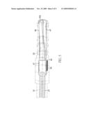
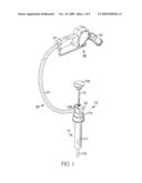
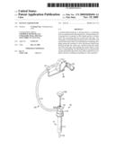
[0010]FIG. 1 is a perspective view of a manual liquid pump in accordance with the present invention;
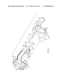
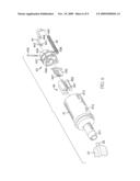
[0011]FIG. 2 is an enlarged, exploded perspective view of a drawing device of the manual liquid pump in FIG. 1;
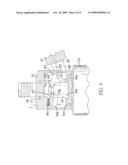
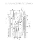
[0012]FIG. 3 is an enlarged side view in partial section of the drawing device of the manual liquid pump in FIG. 1;
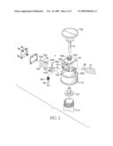
[0013]FIG. 4 is an enlarged exploded view of an outlet gun of the manual liquid pump in FIG. 1;
[0014]FIG. 5 is an enlarged top view of the outlet gun of the manual liquid pump in FIG. 1, showing internal elements;
[0015]FIG. 6 is an enlarged exploded view of a detecting device of the manual liquid pump in FIG. 4;
[0016]FIG. 7 is enlarged side view in partial section of the detecting device of the manual liquid pump in FIG. 6;
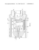
[0017]FIG. 8 is an operational side view of the detecting device of the manual liquid pump in FIG. 7; and
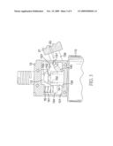
[0018]FIG. 9 is an operational side view in partial section of the drawing device of the manual liquid pump in FIG. 3.
DETAILED DESCRIPTION OF THE PREFERRED EMBODIMENT
[0019]With reference to FIGS. 1, 2 and 4, a manual liquid pump in accordance with the present invention comprises a drawing device (10), a connecting tube (20), an outlet gun (30) and a detecting device (40).
[0020]The drawing device (10) has a body (11), a drawing mount (12), a piston rod (13), a pushing block (14), a pivot seat (15) and a caution shaft (16).
[0021]The body (11) has a drawing barrel (111) and a mounting ring (113). The drawing barrel (111) is used to insert into a container (not shown) and has a top, a bottom, a center and a drawing pipe (112). The drawing pipe (112) is formed on the bottom of the drawing barrel (111). The mounting ring (113) is hollow, is detachably connected to the drawing barrel (111) and has a bottom and a top. The bottom of the mounting ring (113) is detachably mounted around the top of the drawing barrel (111).
[0022]With further reference to FIG. 3, the drawing mount (12) is formed on the body (11) and has a top, a bottom, a sidewall, an internal surface, a chamber (121), a rod hole (122), two drawing holes (123), a dovetail groove (124), a shaft hole (125), an output tube (126) and a pivotal recess (127). The bottom of the drawing mount (12) is formed on the top of the mounting ring (113) of the body (11). The chamber (121) is defined in the drawing mount (12). The rod hole (122) is formed in the top of the drawing mount (12) and communicates with the chamber (121) and aligns with the center of the drawing barrel (111). The drawing holes (123) are formed in the bottom of the drawing mount (12) and communicate with the chamber (121) and the drawing barrel (111). The dovetail groove (124) is formed in the bottom of the drawing mount (12) near the drawing holes (123). The shaft hole (125) is formed in the top of the drawing mount (12) and communicates with the chamber (121). The output tube (126) is formed on and protrudes from the sidewall of the drawing mount (12) and communicates with the chamber (121). The pivotal recess (127) is formed in the internal surface of the drawing mount (12) near the output tube (126).
[0023]The piston rod (13) is movably mounted in the body (11) and the drawing mount (12) and the piston rod (13) has an inner end, an outer end, an external surface, a check valve (131) and an operating head (132). The inner end of the piston rod (13) extends into the body (11) through the rod hole (122) and into the chamber (121) of the drawing mount (12). The check valve (131) is connected to the inner end of the piston rod (13) and mounted between the drawing barrel (111) and the mounting ring (113). The outer end of the piston rod (13) extends out of the top of the drawing mount (12) from the rod hole (122). The operating head (132) is formed on the outer end of the piston rod (13) to allow the piston rod (13) to be moved up or down relative to the drawing mount (12) and the body (11).
[0024]The pushing block (14) is mounted securely in the drawing mount (12) and has a top, a bottom, a sidewall, an inserting hole (141), a pushing axle (142) and a returning conduit (143). The inserting hole (141) is formed in the top of the pushing block (14). The pushing axle (142) is movably mounted in the inserting hole (141) of the pushing block (14) and has a top end. The returning conduit (143) is formed on and protrudes from the sidewall of the pushing block (14) and aligns with the output tube (126) of the drawing mount (12).
[0025]The pivot seat (15) is pivotally mounted in the drawing mount (12), abuts the pushing block (14) and has a top, a bottom, a mounting segment (151), an engaging hole (152), a pushing segment (153) and a lifting segment (154). The mounting segment (151) is defined in the bottom of the pivot seat (15) and is pivotally mounted in the mounting recess (127) of the drawing mount (12). The engaging hole (152) is formed through the top and the bottom of the pivot seat (15) and is mounted around the piston rod (13). The pushing segment (153) is defined in the top of the pivot seat (15) and abuts the top end of the pushing axle (142) of the pushing block (14). The lifting segment (154) is defined in the bottom of the pivot seat (15) opposite to the mounting segment (151) and aligns with the shaft hole (125) of the drawing mount (12).
[0026]The caution shaft (16) is mounted in the chamber (121) of the drawing mount (12), abuts the pivot seat (15) and has a lower end, an upper end and a mounting spring (161). The lower end of the caution shaft (16) abuts the lifting segment (154) of the pivot seat (15) to hold the caution shaft (16) in the chamber (121) of the drawing mount (12). The upper end of the caution shaft (16) is mounted in the shaft hole (125) of the drawing mount (12). The mounting spring (161) is mounted around the caution shaft (16) between the internal surface of the drawing mount (12) and the lower end of the caution shaft (16).
[0027]With further reference to FIG. 6, the connecting tube (20) is connected to the drawing device (10) and has a distal end, an outer pipe (21), and an inner pipe (22). The outer pipe (21) is connected to the drawing mount (12) of the drawing device (10) and has a rear end and a front end. The rear end of the outer pipe (21) is mounted around the output tube (126) of the drawing mount (12) and communicates with the chamber (121) of the drawing mount (12) and the drawing barrel (111) of the body (11). The inner pipe (22) is mounted in the outer pipe (21) and is connected to the pushing block (14) of the drawing device (10) and has a rear end and a front end. The rear end of the inner pipe (22) is mounted in the returning conduit (143) of the pushing block (14) through the output tube (126) and communicates with the inserting hole (141) of the pushing block (14).
[0028]With further reference to FIG. 5, the outlet gun (30) is implemented with two half-casings and is connected to the distal end of the connecting tube (20) and has a rear end, a middle, a front end, a handle (31), an interior (32) and a nozzle (33).
[0029]The handle (31) is formed in the rear end of the outlet gun (30) and is mounted around the front end of the outer pipe (21) of the connecting tube (20).
[0030]The interior (32) is defined in the middle of the outlet gun (30) and receives the front ends of the outer pipe (21) and the inner pipe (22).
[0031]The nozzle (33) is formed in the front end of the outlet gun (30) and has a free end, an opening (331) and a holding panel (332). The opening (331) is defined in the free end of the nozzle (33) and communicates with the interior (32). The holding panel (332) is semicircular and is mounted in the opening (331) of the nozzle (33) and has a holding hole (333). The holding hole (333) is formed in the holding panel (332).
[0032]With further reference to FIG. 7, the detecting device (40) is mounted in the outlet gun (30) and has a mounting jacket (41), a returning seat (42), a returning valve (43), an actuating element (44), a returning spring (45), a flow pipe (46) and a floating shaft (47).
[0033]The mounting jacket (41) is mounted in the interior (32) of the outlet gun (30), is connected to the outer pipe (21) of the connecting tube (20) and has a rear end, a front end, an external surface, an attachment tube (411), a mounting chamber (412), a gap (413) and a hook (414). The attachment tube (411) is formed on the rear end of the mounting jacket (41) and mounted in the front end of the outer pipe (21). The mounting chamber (412) is defined in the mounting jacket (41) near the front end and communicates with the attachment tube (411) and the inner pipe (22) extends into the mounting chamber (412) of the mounting jacket (41). The gap (413) is formed through the external surface of the mounting jacket (41) in the front end and communicates with the mounting chamber (412). The hook (414) is formed on and protrudes from the external surface of the mounting jacket (41) near the rear end and aligns with the gap (413).
[0034]The returning seat (42) is mounted in the mounting jacket (41), is connected to the inner pipe (22) of the connecting tube (20) and has a center, a central tube (421) and multiple fins (422). The central tube (421) is formed on the center of the returning seat (42) and communicates with the attachment tube (411) and the mounting chamber (412) of the mounting jacket (41) and is mounted in the front end of the inner pipe (22). The fins (422) are parallelly formed around the central tube (421) in at even intervals.
[0035]The returning valve (43) is connected to the mounting jacket (41) and has a base (431), a cover (432) and a pivot shaft (433). The base (431) is connected to the front end of the mounting jacket (41) and has an inner end, an outer end, an external surface, a through hole (434), a pivot hole (435) and a slit (436). The inner end of the base (431) is mounted in the mounting chamber (412) of the mounting jacket (41). The through hole (434) is formed through the base (431) and communicates with the mounting chamber (412) of the mounting jacket (41). The pivot hole (435) is formed through the base (431) and communicates with the through hole (434). The slit (436) is formed through the external surface of the base (431) and communicates with the through hole (434) and the pivot hole (435) and aligns with the gap (413) of the mounting jacket (41).
[0036]The cover (432) is pivotally connected to the inner end of the base (431) to selectively close the through hole (434) of the base (431) and has a bottom face and two guiding tracks (437). The bottom face of the cover (432) faces the through hole (434) of the base (431). The guiding tracks (437) are formed parallelly on the bottom face of the cover (432). The pivot shaft (433) is mounted in the pivot hole (435) of the base (431).
[0037]The actuating element (44) may be number-3 shaped, is pivotally connected to the returning valve (43) and has a connecting end (441), a middle, a mounting end (442), two guiding posts (443) and a circular hole (444). The connecting end (441) of the actuating element (44) passes through the through hole (434) of the base (431) and is connected to the cover (432). The middle of the actuating element (44) is mounted in the slit (436) of the base (431) and is pivotally connected to the pivot shaft (433). The mounting end (442) of the actuating element (44) extends out of the outer end of the base (431). The guiding posts (443) are formed on the connecting end (441) and are movably mounted in guiding tracks (437) of the cover (432). The circular hole (444) is formed through the middle of the actuating element (44) and is mounted around the pivot shaft (433).
[0038]The returning spring (45) is attached to the mounting jacket (41) and the actuating element (44) and has two ends. One of the ends of the returning spring (45) is mounted on the hook (414) of the mounting jacket (41). The other end of the returning spring (45) is mounted on the mounting end (442) of the actuating element (44).
[0039]The flow pipe (46) is mounted in the nozzle (33) of the outlet gun (30), is connected to the returning valve (43) and the holding panel (332) of the nozzle (33) and has a rear end and a front end. The rear end of the flow pipe (46) is mounted around the outer end of the base (431) of the returning valve (43). The front end of the flow pipe (46) is mounted in the holding hole (333) of the holding panel (332).
[0040]The floating shaft (47) is movably mounted in the nozzle (33) of the outlet gun (30) parallel to the flow pipe (46) and has an inner end and an outer end. The inner end of the floating shaft (47) is mounted in the nozzle (33) near the outer end of the base (431) and abuts the actuating element (44) near the mounting end (442). The outer end of the floating shaft (47) extends to the free end of the nozzle (33).
[0041]When the manual liquid pump is used to transport liquid from a container to another one, the mounting barrel (111) and the drawing pipe (112) of the body (11) are placed in a container and the nozzle (33) of the outlet gun (30) is placed in a tank. Then, the operating head (132) of the piston rod (13) is moved reciprocatorily to make the check valve (131) move relative to the mounting barrel (111). Then, the liquid will draw and transport liquid from the container to the tank through the drawing pipe (112), the mounting barrel (111), the drawing holes (123), the chamber (121), the output tube (126), the outer pipe (21), the attachment tube (411), the returning seat (42), the through hole (434) of the base (431) and the flow pipe (46).
[0042]With reference to FIGS. 8 and 9, when the liquid is drawn to fill the tank, the liquid in the tank will flow back up the nozzle (33) and make the floating shaft (47) move further into the nozzle (33). Then, the inner end of the floating shaft (47) will push the mounting end (442) of the actuating element (44) to rotate relative to the base (431) and the connecting end (441) of the actuating element (44) will make the cover (432) close the through hole (434) of the base (431).
[0043]Should the piston rod (13) remain in operation, liquid flowing into the mounting jacket (41) will be stopped by the cover (432) closing the through hole (434) of the base (431) and will flow into the inserting hole (141) of the pushing block (14) via the central tube (421), the inner pipe (22) and the returning conduit (143). As the inserting hole (141) fills up with the liquid, the pushing axle (142) will move upward relative to the pushing block (14) and the top end of the pushing axle (142) will push the pushing segment (153) of the pivot seat (15) upward. Then, the mounting segment (151) of the pivot seat (15) will move relative to the mounting recess (127) to make the pivot seat (15) rotate relative to the drawing mount (12). With rotation of the pivot seat (15) relative to the drawing mount (12), the engaging hole (152) of the pivot seat (15) will engage the external surface of the piston rod (13) and the upper end of the caution shaft (16) will extend out of the shaft hole (125) of the drawing mount (12). This reminds a user to stop moving the piston rod (13) to prevent the liquid from flowing over the container. Therefore, the manual liquid pump can be operated safely.
[0044]Even though numerous characteristics and advantages of the present invention have been set forth in the foregoing description, together with details of the structure and features of the invention, the disclosure is illustrative only. Changes may be made in the details, especially in matters of shape, size, and arrangement of parts within the principles of the invention to the full extent indicated by the broad general meaning of the terms in which the appended claims are expressed.
User Contributions:
comments("1"); ?> comment_form("1"); ?>Inventors list |
Agents list |
Assignees list |
List by place |
Classification tree browser |
Top 100 Inventors |
Top 100 Agents |
Top 100 Assignees |
Usenet FAQ Index |
Documents |
Other FAQs |
User Contributions:
Comment about this patent or add new information about this topic:
Images included with this patent application:
 |  |
 |  |
 |  |
 |  |
 |  |
 |  |
| Similar patent applications: | |
| Date | Title |
|---|---|
| 2009-08-27 | Mechanical liquid pump |
| 2010-10-07 | mechanical sealing device, and a pump |
| 2012-11-15 | Modulating liquid pump |
| 2008-11-20 | Gas-driven liquid pump |
| 2009-04-23 | Liquid cartridge and liquid pump |
| New patent applications in this class: | |
| Date | Title |
|---|---|
| 2016-09-01 | Method for operating a pump unit, pump unit and use thereof |
| 2015-05-28 | Test and monitoring system for a sump pump installation operable from a remote location |
| 2015-03-05 | Autonomous water extraction system and method of use |
| 2015-02-12 | Pump control system having emergency run mode |
| 2014-06-12 | Pneumo-hydraulic sump water evacuation system |
| Top Inventors for class "Pumps" | |
| Rank | Inventor's name |
|---|---|
| 1 | Masaki Ota |
| 2 | Ken Suitou |
| 3 | Alex Horng |
| 4 | Yusuke Yamazaki |
| 5 | Lars Hoffmann Berthelsen |