Patent application title: Mounting arrangement for a knot brush
Inventors:
James Teeple (Archbald, PA, US)
Larry Mell (Lake Ariel, PA, US)
David Bennett (Cresco, PA, US)
IPC8 Class: AA44B108FI
USPC Class:
24 93
Class name: Buckles, buttons, clasps, etc. button with fastener multiple attachment
Publication date: 2009-11-05
Patent application number: 20090271955
Inventors list |
Agents list |
Assignees list |
List by place |
Classification tree browser |
Top 100 Inventors |
Top 100 Agents |
Top 100 Assignees |
Usenet FAQ Index |
Documents |
Other FAQs |
Patent application title: Mounting arrangement for a knot brush
Inventors:
James Teeple
Larry Mell
David Bennett
Agents:
DRINKER BIDDLE & REATH;ATTN: INTELLECTUAL PROPERTY GROUP
Assignees:
Origin: PHILADELPHIA, PA US
IPC8 Class: AA44B108FI
USPC Class:
24 93
Patent application number: 20090271955
Abstract:
A knot brush with a knot plate having a plurality of perforations disposed
circumferentially about the plate near an outer rim. A plurality of
mounting holes are formed through the knot plate and are spaced apart
from one another. Each mounting hole is located at a radial position that
is inward from the perforations. A plurality of wire bundles are attached
to the knot plate. Each wire bundle includes a center portion extending
through a perforation and two end portions twisted together securing the
bundle to the knot plate. Two side plates are attached to the knot plate.
Each side plate includes protrusions extending out from the side plate
and into the mounting holes. One side plate is punched into a protrusion
on the other side plate forming an interlocking button that extends from
the surface of the side plate and locking the side plates together.Claims:
1. A knot brush comprising:a knot plate having a plurality of perforations
formed through the knot plate, the perforations being disposed
circumferentially about the plate near a radially outer rim of the knot
plate, and a plurality of mounting holes formed through the knot plate,
the mounting holes being spaced apart from one another on the knot plate,
each mounting hole located at a radial position inward from the
perforations;a plurality of wire bundles attached to the knot plate, each
wire bundle including two opposed end portions with a center portion
extending through an associated perforation in the knot plate, the end
portions being at least partially twisted together so as to secure the
bundle to the knot plate;first and second side plates attached to the
knot plate, each side plate including an annular central portion and
curved support rim, the curved support rim adapted to assist in
supporting the wire bundles, each side plate including at least two
protrusions extending out from the surface of the annular portion, the
protrusions being spaced apart from one another and forming a recess on
the opposite surface of the side plate, each protrusion being located at
a radial position relative to the center of the side plate such that each
protrusion extends into an associated mounting hole; andat least one
interlocking button protruding from an outer facing surface of at least
the first side plate and formed by a portion of the second side plate
being deformed into the first side plate so as to mechanically interlock
the two side plates and protrude from the outer facing surface of that
side plate.
2. A knot brush according to claim 1 wherein the button is formed in one of the protrusions and extends into the recess associated with that protrusion.
3. A knot brush according to claim 2 wherein there are multiple buttons, each one formed in one of the protrusions.
4. A knot brush according to claim 2 wherein the knot plate has a thickness that is greater than the thickness of each side plate, wherein the perforations are slotted holes formed in the knot plate, the perforations being spaced substantially equally apart from one another and located at a common radial position from the center of the knot plate, and wherein each side plate includes half as many protrusions as there are mounting holes in the knot plate.
5. A knot brush according to claim 2 wherein there are six mounting holes substantially equally spaced circumferentially on the knot plate; and wherein there are three protrusions on each side plate substantially equally spaced circumferentially on the side plate, the side plates being substantially identical except that the protrusions on one side plate are offset from the protrusions on the other side plate by 60 degrees when the side plates are mounted to the knot plate.
6. A knot brush according to claim 4 wherein each slotted hole has a length of about 0.200 inches and a width of about 0.125 inches.
7. A knot brush according to claim 6 wherein the knot plate has a diameter of about 4.38 inches and a thickness of about 0.110 inches, and wherein there are at least 76 perforations formed in the knot plate, each perforation centered about 1.984 inches from the center of the knot plate.
8. A knot brush according to claim 5 wherein each side plate preferably has a diameter of about 4.72 inches and a thickness of about 0.05 inches, the central portion being substantially planar is shape, wherein the knot plate has a diameter of about 4.38 inches and a thickness of about 0.110 inches, and wherein there are at least 76 perforations formed in the knot plate, each perforation centered about 1.984 inches from the center of the knot plate.
9. A knot brush according to claim 5 wherein the protrusions are substantially circular in shape with an outer diameter of about 0.571 inches and protrude from the central portion of the side plate by about 0.105 inches, and wherein the protrusions are spaced approximately 120 degrees apart from one another.
10. A knot brush according to claim 5 wherein the centers of the mounting holes are located about 1.496 inches from the center of the knot plate, and wherein each mounting hole has a diameter of about 0.610 inches and is located 60 degrees from an adjacent mounting hole.
11. A knot brush comprising:a knot plate having a plurality of perforations formed through the knot plate, the perforations being disposed circumferentially about the plate near a radially outer rim of the knot plate, and a plurality of mounting holes formed through the knot plate, the mounting holes being spaced apart from one another on the knot plate, each mounting hole located at a radial position inward from the perforations;a plurality of wire bundles are attached to the knot plate, each wire bundle including two opposed end portions and a center portion extending through an associated perforation in the knot plate, the end portions being at least partially twisted together so as to secure the bundle to the knot plate;two side plates attached to the knot plate, the side plates being substantially identical to one another and including an annular central portion and curved support rim, the curved support rim adapted to assist in supporting the wire bundles, each side plate including at least three protrusions extending out from a surface of the annular portion, each protrusion forming a recess on the opposite surface of the side plate, the protrusions being spaced apart from one another on each side plate, each protrusion being located on the side plate such that each protrusion on a side plate extends into an associated mounting hole in the knot plate but is not aligned with any protrusions on the other side plate; anda plurality of interlocking buttons protruding out from a surface of a side plate, each button located in one of the recesses on a side plate, each interlocking button formed by a portion of the one side plate being deformed into the other side plate so as to mechanically interlock the two side plates and protrude from the outer facing surface of the other side plate.
12. A method of forming a knot brush comprising the steps of:forming a plurality of perforations through a knot plate, the perforations being disposed circumferentially about the plate near a radially outer rim of the knot plate;forming a plurality of mounting holes in the knot plate, the mounting holes being spaced apart from one another on the knot plate, each mounting hole being located at a radial position inward from the radial location of the perforations;providing a plurality of wire bundles, each wire bundle having two opposed end portions,inserting one end portion of each wire bundle through an associated perforation in the knot plate;twisting the two end portions at least partially along their length so as to secure the bundle to the knot plate;forming first and second side plates, each side plate having an annular central portion and curved support rim, the curved support rim adapted to assist in supporting the wire bundles;forming at least two protrusions on each side plate, the protrusions extending out from the surface of the annular portion, the protrusions being spaced apart from one another;placing the first side plate on one side of the knot plate so that each protrusion on the side plate is aligned with one mounting hole on the knot plate;placing the second side plate on the opposite side of the knot plate so that each protrusion on the second side plate is aligned with one mounting hole on the knot plate; andpunching a portion of one side plate into a protrusion on the other side plate so as to force the punched materials on both side plates to deform and form an interlocking button on the opposite surface of the other side plate, the interlocking button of material locking the side plates to each other and retaining the knot plate.
13. A method of forming a knot brush according to claim 12 wherein the two side plates are formed so as to be substantially identical, and wherein prior to the step of placing the second side plate on the knot plate, the method involves orienting the second side plate so that the protrusions on the second side plate are not aligned with the protrusions on the first side plate.
14. A method of forming a knot brush according to claim 13 wherein each side plate includes three protrusions and the knot plate includes six mounting holes; and wherein the step of orienting the second side plate results in the protrusions on the second side plate being offset by 60 degrees from the protrusions on the first side plate.
15. A method of forming a knot brush comprising the steps of:forming a knot plate having a plurality of perforations extending through the knot plate, the perforations being disposed circumferentially about the plate near a radially outer rim of the knot plate, the knot plate having a plurality of mounting holes spaced apart from one another, each mounting hole being at a radial position inward from the radial location of the perforations;attaching a plurality of wire bundles to the knot plate, each wire bundle being attached to an associated perforation by inserting one end portion of the wire bundle through the perforation in the knot plate and twisting the end portion of the wire bundle to an opposite end portion of the wire bundle so as to secure the bundle to the knot plate;forming first and second side plates, each side plate having an annular central portion and curved support rim, the curved support rim adapted to assist in supporting the wire bundles, each side plate having at least two protrusions extending out from a surface of the annular portion, the protrusions being spaced apart from one another;placing the first side plate on one side of the knot plate so that each protrusion on the side plate is aligned with one mounting hole on the knot plate;placing the second side plate on the opposite side of the knot plate so that each protrusion on the second side plate is aligned with one mounting hole on the knot plate while being offset from the protrusions on the first side plate; andpunching a portion of the first side plate into a protrusion on the second side plate so as to force the punched materials on both side plates to deform and form an interlocking button on the opposite surface of the second side plate, the interlocking button of material locking the side plates to each other and retaining the knot plate.
Description:
FIELD OF THE INVENTION
[0001]The present invention is directed to knot brushes and, more particularly, to an improved mounting arrangement for a knot brush that simplifies assembly while providing support for the knot.
BACKGROUND
[0002]Knot brushes have been around for many years. U.S. Pat. No. 4,504,997 describes one conventional knot brush design. The brush includes a plurality of radially extending twisted wire bundles. Each wire bundle is separately attached to a central disc or knot plate. The attachment is provided by passing a wire bundle through one of a plurality of circumferentially spaced holes formed in the knot plate and then twisting both ends of the wire bundle together to form the twisted knot.
[0003]In order to support the wire bundle, conventional knot brushes include side plates that are attached to opposite sides of the knot plate and crimped around the wire bundles to secure the knots. The side plates and knot plate are then welded together to form the final brush assembly. These conventional brushes are costly and time consuming to manufacture.
[0004]A need exists for an improved knot brush mounting arrangement that simplifies assembly while providing support for the knot.
SUMMARY OF THE INVENTION
[0005]The present invention is directed to an improved knot brush assembly that includes a knot plate having a plurality of perforations formed through the knot plate and disposed circumferentially about the plate near a radially outer rim. A plurality of mounting holes are formed through the knot plate and are spaced apart from one another, Each mounting hole is located at a radial position that is inward from the perforations.
[0006]A plurality of wire bundles are attached to the knot plate. Each wire bundle includes two opposed end portions with the center of the wire bundle extending through an associated perforation in the knot plate. The end portions are at least partially twisted together so as to secure the bundle to the knot plate.
[0007]The knot brush includes two side plates that are attached to the knot plate. Each side plate includes an annular central portion and curved support rim. The curved support rim is configured to assist in supporting the wire bundles. Each side plate also includes at least two protrusions extending outward from the surface of the annular portion and forming a recess on the opposite side of the plate. The protrusions are spaced apart from one another on the side plate and located at a radial position relative to the center of the side plate such that each protrusion seats within an associated mounting hole. In order to attach the side plates to one another, a portion of one side plate is deformed into the protrusion of the other side plate, thereby mechanically locking the two plates together. Preferably the deformation is formed by punching the material of one plate into the other so as to form a raised button in the recessed portion of the other plate. The attachment of the two side plates together retains knot plate between the two side plates.
[0008]In one embodiment, the perforations are slotted holes formed in the knot plate and are spaced substantially equally apart from one another and at a common radial position from the center of the knot plate. Each side plate includes half as many protrusions as there are mounting holes in the knot plate.
[0009]Preferably there are six mounting holes substantially equally spaced circumferentially on the knot plate and three protrusions on each side plate substantially equally spaced circumferentially on the central portion of the side plate. The side plates are preferably substantially identical except that the protrusions on one side plate are offset from the protrusions on the other side plate by 60 degrees when the side plates are mounted to the knot plate.
[0010]A method of assembling the knot brush is also disclosed.
[0011]The foregoing and other features of the invention and advantages of the present invention will become more apparent in light of the following detailed description of the preferred embodiments, as illustrated in the accompanying figures. As will be realized, the invention is capable of modifications in various respects, all without departing from the invention. Accordingly, the drawings and the description are to be regarded as illustrative in nature, and not as restrictive.
BRIEF DESCRIPTION OF THE DRAWINGS
[0012]For the purpose of illustrating the invention, the drawings show a form of the invention which is presently preferred; it being understood, however, that the invention is not limited to the precise arrangement and instrumentality shown.
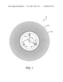
[0013]FIG. 1 is a plan view of a completely assembled knot brush according to the present invention.
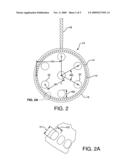
[0014]FIG. 2 is a plan view of a knot plate used in the knot brush of FIG. 1 illustrating one bristle bundle knotted to the knot plate.
[0015]FIG. 2A is an enlarged view taken from FIG. 2 illustrating the perforations.
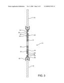
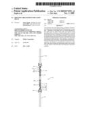
[0016]FIG. 3 is a cross-sectional side view of the knot brush.
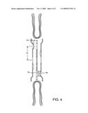
[0017]FIG. 4 is an exploded cross-sectional side view of the know brush prior to assembly.
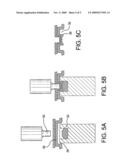
[0018]FIGS. 5A-5C illustrate the process of mechanically interlocking the two side plates together.
DETAILED DESCRIPTION OF THE PREFERRED EMBODIMENT
[0019]Referring to the drawings, wherein like numerals indicate like elements, an embodiment of the knot brush 10 is shown that is preferred. The knot brush 10 includes a knot plate 12 which has a plurality of circumferentially spaced perforations or holes 14 in close proximity to a rim 16 of the plate 12. Preferably the perforations are evenly spaced and located at a common radial position.
[0020]In the illustrated embodiment, the knot plate has a diameter of about 4.38 inches and a thickness of about 0.110 inches. The perforations 14 are preferably slotted or elliptical holes. Each hole has a length (H1) of about 0.200 inches and a width (H2) of about 0.125 inches. There are preferably about 76 holes spaced substantially equally apart and centered at a radial distance (H3) about 1.984 inches from the center of the knot plate.
[0021]Wire or bristle bundles 18 are attached to the plate in a conventional manner by passing an end portion of the bundle 18 through one of the perforations 14 and looping it back. The end portions are then twisted together at least partially along the length of the bundle, so as to form a twisted bundle or knot that is looped about through the perforation. The are other ways known to those skilled in the art for attaching wire bundles to the knot plate and, thus, no further discussion is necessary.
[0022]The knot brush 10 includes two side plates 20, 22, that are located on either side of the knot plate 12 and attached to the knot plate 12 as discussed below. The side plates 20, 22 are preferably identical with respect to their general configuration and each include an annular central portion 24 that is substantially planar in shape, and a curved support rim 26 with a radius that is designed to substantially match the radius of the looped portion 28 of the wire bundle. This curved support rim 26 assists in holding the wire bundles 18 in place.
[0023]In the illustrated embodiment, each side plate 20, 22 preferably has a diameter of about 4.72 inches and a thickness of about 0.05 inches.
[0024]In conventional knot brushes, the side plates and knot plate are welded together. However, doing so adds additional time and expense to the manufacturing process. The present invention overcomes the deficiencies associated with the prior art mounting arrangements. More particularly, the knot plate 12 includes a plurality of mounting holes 32 formed through the plate, radially inward from the perforations 14. As shown the figures, the holes are spaced apart from each other. In one preferred embodiment, there are an equal number of holes. The mounting holes 32 are preferably equally spaced circumferentially and at a common radial location.
[0025]In the illustrated embodiment, the mounting holes 32 are formed through the knot plate 12 with their centers located on a 2.992 inch diameter base circle, i.e., a radius (M1) of 1.496 inches from the center of the knot plate 12. Each mounting hole 32 preferably has a diameter (M2) of about 0.610 inches and is angularly spaced (M3) 60 degrees from an adjacent hole 32.
[0026]Each side plate includes at least two and more preferably at least three protrusions 34 extending outward from one surface of each side plate and are designed to seat within the mounting holes 32 as will be discussed below. Each protrusion 34 forms a recess 36 on the opposite surface of the side plate. In one preferred embodiment, each side plate includes half as many protrusions as there are mounting holes in the knot plate. In the illustrated embodiment, there are three protrusions 34 substantially equally spaced circumferentially on the planar portion of the side plate at a radial distance (P1) of about 1.496 inches from the center of the knot plate 12. Thus, the protrusions are preferably located at the same radial location on the side plates as the mounting holes are on the knot plate.
[0027]The protrusions 34 preferably have a size and shape designed to mate with the mounting holes 32. More specifically, the protrusions 34 are designed to seat within the mounting holes as shown in FIG. 3. In the illustrated embodiment, the protrusions are substantially circular in shape with an outer diameter (P2) of about 0.571 inches and a depth (P3) of about 0.105 inches. The protrusions 34 extend (protrude) out from the surface of the side plate that contacts the knot plate. The protrusions are spaced (P4) approximately 120 degrees apart from one another in the illustrated embodiment.
[0028]As should be apparent from the above discussion, in the preferred embodiment, since each side plate includes half the number of protrusions as there are mounting holes in the knot plate, and since the protrusions are equally spaced, identical side plates can be used on opposite sides of the knot plate; provided that one plate is rotated so as to orient its protrusions 34 so that they do not align with the protrusions on the other side plate. For example, as shown in the illustrated embodiment, since each side plate includes three protrusions, rotating one side plate 60 degrees will result in each protrusion on a side plate seating within a unique mounting hole. This reduces the number of component parts that are necessary to form the knot brush assembly 10.
[0029]In order to secure the sides and knot plates to each other, the present invention uses a mechanical interlocking mechanism. One of the problems with trying to interlock conventional knot brushes is that it is not possible to physically deform two side plates and a knot plate. The present invention overcomes this problem by forming the interlocking or self riveting in the holes of the knot plate. Specifically, a portion of one side plate is deformed into the protrusion on the other side plate causing the material of the two side plates to interlock, thereby preventing disengagement. The deformation of one side plate into the protrusion creates a raised button or rivet shaped swelling 38 or protuberance on the opposite side of one of the layers that is preferably located within the recess 36. The button 38 interlocks the two layers together. Since the side plates are interlocked to one another within the holes of the knot plate, the knot plate is secured between the side plates as shown in FIG. 3. Also, locating the button 38 in the recess 36 minimizes sharp protrusions on the knot brush/
[0030]The knot brush 10 is preferably formed as follows. The perforations 14 and mounting holes 32 are formed in the knot plate 12 using any conventional method known to those skilled in the art including laser cutting, punching, drilling, casting, etc. The side plates 20, 22, including the protrusions, are likewise formed using any conventional method known to those skilled in the art.
[0031]A side plate is placed on either side of a knot plate and oriented such that each protrusion 34 aligns with an associated mounting hole 32. One of the benefits of the present invention is the mounting holes in the knot plate provide an easy mechanism for aligning the side plates since the protrusions will naturally seat within the holes.
[0032]In order to attach the side plates together a self-riveting process is used. This process involves punching one side plate into the protrusion on the other side plate so as to form a button or rivet shaped swelling or protuberance on the opposite side of one of the layers. The protuberance interlocks the two layers together. One system that the applicants have found to work is the TOX® cinching system available from TOX Presstechnik LLC, Warrenville Ill. That system is generally depicted in FIGS. 5A-5C and uses a punch 50 and die 52. The punch 50 is forced into the outer facing surface of one side plate and deforms the a portion of the first side plate into the protrusions of the second side plate as shown in FIG. 5B and into the die 52. The die forces the deformed material to create the button. The punch 50 and die 52 are withdraw leaving a button 38 of interlocked material as shown in FIG. 5c. Pressure can be applied using an hydraulic, pneumatic or similar press. This process effectively self rivets the side plates to each other.
[0033]The use of the novel self-riveting process eliminates the need for a separate and costly welding operation. The size of the buttons discussed above result in more metal of the side plates engaging the knot plate than conventional welding, thus forming a better and stronger attachment to the knot plate.
[0034]While the illustrated embodiment shows the side plates with the protrusions formed prior to assembly, it is also contemplated that the protrusions can be formed during the step of pressing the side plates into the knot plate. The die can force the material of the side plate to deform into the mounting holes during the attachment process as the button is formed.
[0035]Although the invention has been described and illustrated with respect to the exemplary embodiments thereof, it should be understood by those skilled in the art that the foregoing and various other changes, omissions and additions may be made therein and thereto, without parting from the spirit and scope of the present invention.
User Contributions:
comments("1"); ?> comment_form("1"); ?>Inventors list |
Agents list |
Assignees list |
List by place |
Classification tree browser |
Top 100 Inventors |
Top 100 Agents |
Top 100 Assignees |
Usenet FAQ Index |
Documents |
Other FAQs |
User Contributions:
Comment about this patent or add new information about this topic:
| People who visited this patent also read: | |
| Patent application number | Title |
|---|---|
| 20110088334 | ARTICLE AND METHOD FOR CONTROLLING MOISTURE |
| 20110088333 | PREFABRICATED ELEMENT FOR A DWELLING UNIT |
| 20110088327 | OVERHEAD DOORS AND ASSOCIATED TRACK AND GUIDE ASSEMBLIES FOR USE WITH SAME |
| 20110088326 | SPACE ENCLOSURE SYSTEM |
| 20110088310 | CRAWLING INSECT BAIT STATION WITH INTERNAL BAIT RESERVOIR SEAL AND SIMULTANEOUSLY ADJUSTABLE INSECT ACCESS PORT AND CRAWLSPACE DIMENSIONS |
Images included with this patent application:
 |  |
 |  |
 |  |
| Similar patent applications: | |
| Date | Title |
|---|---|
| 2013-11-21 | Sealing arrangement |
| 2014-02-27 | Locking system for jewelry |
| Top Inventors for class "Buckles, buttons, clasps, etc." | |
| Rank | Inventor's name |
|---|---|
| 1 | Keiichi Keyaki |
| 2 | Andreas Hörtnagl |
| 3 | Toshio Iwahara |
| 4 | Joachim Fiedler |
| 5 | Allison S. Conner |