Patent application title: Automatic-positioning linear guide
Inventors:
Shu-Fu Tsai (Taichung City, TW)
IPC8 Class: AF16C3102FI
USPC Class:
384 7
Class name: Bearings linear bearing
Publication date: 2009-10-29
Patent application number: 20090268993
Inventors list |
Agents list |
Assignees list |
List by place |
Classification tree browser |
Top 100 Inventors |
Top 100 Agents |
Top 100 Assignees |
Usenet FAQ Index |
Documents |
Other FAQs |
Patent application title: Automatic-positioning linear guide
Inventors:
Shu-Fu Tsai
Agents:
CHARLES E. BAXLEY, ESQUIRE
Assignees:
Origin: NEW YORK, NY US
IPC8 Class: AF16C3102FI
USPC Class:
384 7
Patent application number: 20090268993
Abstract:
An automatic-positioning linear guide has a driven body combined with
guiding rails at two sides of a stationary base via a plurality of
rollers. Each of the rollers is composed of two bearings combined by an
axial shaft and can be assembled with the corresponding guiding rail
without an assembly error therebetween.Claims:
1. An automatic-positioning linear guide, comprising:a stationary base,
having pair of guiding rail sets provided at two lengthwise sides of a
top surface thereof, wherein each of the guiding rail set has at least
one guiding rail provided at one lengthwise lateral thereof and the
guiding rail has a roller contacting portion jutting out the lateral of
the guiding rail set; anda driven body, mounted on the stationary base,
wherein at least one roller is provided at each of two sides of a bottom
surface of the driven body and each said roller comprises two bearings
and an axial shaft combining and fastening the two bearings to the driven
body, in which two outer bushes of the two bearings jointly define an
annular sliding groove at an exterior of the roller so as to receive the
roller contacting portion of the guiding rail, whereby when the outer
bushes of the bearings contact the roller contacting portion, an axis of
the bearings deflects.
2. The automatic-positioning linear guide of claim 1, wherein, a pair of fixing portions are provided along two sides of a top surface of the stationary base so that so that a retaining edge is formed at a point where the stationary base and each said fixing portion meet for allowing the guiding rail set to be fixed at the fixing portion along the retaining edge.
3. The automatic-positioning linear guide of claim 2, wherein, the fixing portion is depressed from the top surface of the stationary base so that an altitudinal difference between the fixing portion and the top surface of the stationary base defines the retaining edge at the point where top surface of the stationary base and a lateral of the fixing portion.
4. The automatic-positioning linear guide of claim 1, wherein, the guiding rail set comprises a first seat and a second seat vertically aligned and a plurality of bolts passing through and fastening the first seat and the second seat to the stationary base, in which the guiding rail has a portion thereof other than the roller contacting portion retained between the first and second seat.
5. The automatic-positioning linear guide of claim 4, wherein, a socket is provided at a top surface of the first seat for receiving a head of each said bolt.
6. The automatic-positioning linear guide of claim 1, wherein, a relative interval exists between the two bearings while the bearings are respectively separated from the axial shaft for another relative interval.
7. The automatic-positioning linear guide of claim 1, wherein, the axial shaft is a bolt.
8. The automatic-positioning linear guide of claim 1, wherein, a plurality of said guiding rail sets are linked up at each of the two sides of the stationary base and the adjacent said guiding rail sets are spaced out an extension gap.
9. The automatic-positioning linear guide of claim 1, wherein, at least one groove is formed on the bottom surface of the driven body between the two rollers and at least one lateral pressure adjusting member is provided parallel to the two sides of the driven body and perpendicularly cross the groove.
10. The automatic-positioning linear guide of claim 9, wherein, the lateral pressure adjusting member comprises a bolt passing across the groove and a nut fixed to the bottom surface of the driven body for receiving the bolt.
11. The automatic-positioning linear guide of claim 4, wherein, a rail receiving portion formed as a quarter round is provided at each of two sides of the first seat and the second seat facing each other so that adjacent said rail receiving portions jointly define a semicircular accommodating space for receiving one said guiding rail in which the guiding rail has the portion thereof other than the roller contacting portion received in the semicircular accommodating space and retained between the first and second seat.
12. The automatic-positioning linear guide of claim 4, wherein, a relative distance exists between the first seat and the second seat.
13. The automatic-positioning linear guide of claim 1, wherein, two rows of said rollers are provided at each of the two sides of the bottom surface of the driven body and each said guiding rail set has a pair of guiding rails settled at each of two lengthwise laterals, whereby when the roller contacting portions of the guiding rails combined with the annular sliding grooves of the rollers, the outer bushes of each said roller contact the corresponding roller contacting portion.
14. The automatic-positioning linear guide of claim 13, wherein, a groove is formed on the bottom surface of the driven body between the two rows of the rollers and a plurality of lateral pressure adjusting members are provided on the driven body and perpendicularly cross the groove.
15. The automatic-positioning linear guide of claim 14, wherein, a lateral pressure adjusting member is provided on the driven body between two adjacent said roller of the same row.
Description:
BACKGROUND OF THE INVENTION
[0001]1. Technical Field
[0002]The present invention relates to linear guides and more particularly, to a linear guide having functions of automatic positioning, automatic assembly-error eliminating, and automatic accumulated-error eliminating.
[0003]2. Description of Related Art
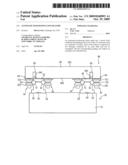
[0004]A conventional roller linear guide, as shown in FIGS. 1, 2 and 3, primarily comprises a rail 10 and a driven body 15 that can move back and forth along the rail 10. Two sides of the driven body 15 are combined with two sides of the rail 10 through a plurality of rollers 16, which assist the driven body 15 in its linear movement with reduced friction as well as noise and smoothes the linear movement of the driven body 15.
[0005]Each of the rollers 16 of the driven body 15 has an integral outer bush 161 where an outer annular groove 162 is formed for receiving a corresponding side of the rail 10.
[0006]People who have ordinary skill in the art of linear guides would appreciate that smooth and steady linear movement of the driven body 15 is available only when each said roller 16 and the rail 10 are mated with high accurateness. Such high accurateness can significantly raise the manufacturing costs of the rail 10 and the rollers 16. However, even if the rail 10 and the rollers 16 are formed with the anticipated accurateness, when the both are later combined together, assembly errors happening therebetween cannot be fully averted, and such assembly errors can accumulate and cause an accumulated assembly error that adversely effect the operation of the linear guide.
[0007]To remedy the problems of the assembly errors and the accumulated assembly error, it has been proposed in the prior art to adjust a position of the axle of each said roller 16 so as to make the outer annular groove 162 of its outer bush 161 accurately engage the rail 10, thereby eliminating possible assembly errors. In such a known approach, referring to FIGS. 1 to 3, each said roller 16 is inlaid to a respective moving block 12, which is fastened to the driven body 15 by a set screw 13 and a bias screw 14. Therefore, by adjusting the bias screw 14, the moving block 12 can slant with respect to the set screw 13 so as to shift the axle of the roller 16 and in turn improve the closeness between the moving block 12 and the rail 10. Consequently, the risk of assembly errors can be eliminated.
[0008]However, while each said roller 16 is adjusted with respect to the rail 10 one by one, the following problems emerge. That is, the closeness between each said rollers 16 and the rail 10 may not be identical and a resulted inequality of mating statuses tends to cause partial variation on the structural tension of the driven body 15, leading to deformation of the driven body 15. In addition, the discrepancy of the mating statuses between the rollers 16 and the rail 10 renders to discrepant attrition on the outer bushes 161 of the rollers 16. Consequently, after a period of use, the assembly errors and accumulated assembly error can become aggravated and the driven body 15 will then be subject to undesirable jolts during its linear movement.
[0009]Besides, since the rollers and rail 10 are assembled relying on manual operation without objective adjustment reference, in the event that the rollers 16 and the rail 10 are combined with undue closeness, the friction therebetween is increased and adversely affects the smooth liner movement of the driven body 15. Besides, the undue friction can significantly reduce the service lives of the rollers 16 and the rail 10.
SUMMARY OF THE INVENTION
[0010]One objective of the present invention is to provide an automatic-positioning linear guide, wherein a driven body is combined with two guiding rails settled at two sides of a stationary base and each roller automatically adjusts a closeness where it is combined with the corresponding guiding rail. In other words, the roller serve to automatically eliminate an assembly error between itself and the corresponding guiding rail and in turn eliminate an accumulated assembly error, thereby achieving a highly precise assembly of the linear guide. It is to be noted that commercially available and ordinary bearings are competent to function as the rollers of the present invention, instead of any component made through special technology or highly precise standards.
[0011]Another objective of the present invention is to provide an automatic-positioning linear guide, wherein a driven body is combined with two guiding rails settled at two sides of a stationary base via a plurality of rollers. The driven body adjusts a lateral pressure thereof and in turn change lateral pressures a plurality of rollers applying to the guiding rails so as to automatically eliminate assembly errors and an accumulated assembly error between the rollers and the guiding rails, so that the rollers and the guiding rails can be assembled with proper closeness
[0012]Another objective of the present invention is to provide an automatic-positioning linear guide, which facilitates preventing deformation of a driven body, ensuring stable movement of the driven body, protecting rollers and guiding rails from bearing an excessive lateral pressure, averting undue attrition of the rollers and the guiding members, and lengthening service lives of the rollers and the guiding rails.
[0013]Another objective of the present invention is to provide an automatic-positioning linear guide, which can be such configured that the linear guide has an arbitrary linear length, wherein preparation as well as assembly of the linear guide are convenient and linear precision as well as smooth movement are ensured.
[0014]To achieve the above objectives, the automatic-positioning linear guide comprises a stationary base and a driven body mounted thereon. Two parallel guiding rail sets are provided on a top surface of the stationary base. Each said guiding rail set comprises a pair of guiding rails of a round-rod shape that are arranged abreast. A bottom surface of the driven body is combined with the guiding rails via a plurality of rollers. Each said roller is composed of two bearings combined by an axial shaft. When reaching the corresponding guiding rail, the two bearings perform a bias with respect to an axial direction thereof so that the roller and the guiding rail are closely fitted without an assembly error therebetween. The guiding rail set further comprises a first seat and a second seat that are vertically aligned to sandwich the guiding rails therebetween.
BRIEF DESCRIPTION OF THE DRAWINGS
[0015]The invention as well as a preferred mode of use, further objectives and advantages thereof, will best be understood by reference to the following detailed description of an illustrative embodiment when read in conjunction with the accompanying drawings, wherein:
[0016]FIG. 1 is a partial perspective view of a conventional roller-type linear guide;
[0017]FIG. 2 is a partial bottom view of the linear guide of FIG. 1;
[0018]FIG. 3 is a lateral view of the linear guide of FIG. 2;
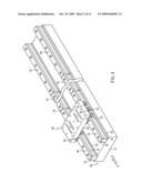
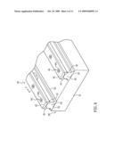
[0019]FIG. 4 is a perspective view of a linear guide of the present invention;
[0020]FIG. 5 is a plane drawing of the linear guide of the present invention made along a direction of Arrow 5 of FIG. 4;
[0021]FIG. 6 is a partial perspective view of a stationary base of the linear guide of the present invention;
[0022]FIG. 7 is a partial sectional view made along line 7-7 of FIG. 6, showing guiding assemblies;
[0023]FIG. 8 is a partially enlarged view of the circle in FIG. 7;
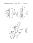
[0024]FIG. 9 is a top view of the driven body of the linear guide according to the present invention;
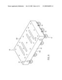
[0025]FIG. 10 is a bottom view of the driven body of the linear guide according to the present invention;
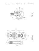
[0026]FIG. 11 is an exploded view of the roller according to the present invention;
[0027]FIG. 12 is an assembly drawing of the roller according to the present invention;
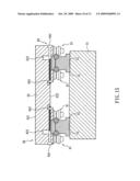
[0028]FIG. 13 is a sectional assembly drawing of the roller according to the present invention;
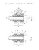
[0029]FIG. 14 is a sectional view of the assembled roller and guiding rail according to the present invention;
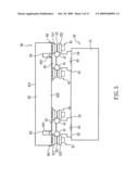
[0030]FIG. 15 is a sectional assembly drawing of the linear guide according to the present invention; and
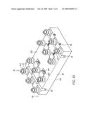
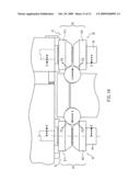
[0031]FIG. 16 is a schematic drawing showing a direction of a force generated when the rollers and the guiding rails are combined.
DETAILED DESCRIPTION OF THE PREFERRED EMBODIMENT
[0032]While a preferred embodiment is provided herein for illustrating the concept of the present invention as described above, it is to be understood that the extent of deformation or displacement of the components in these drawings are made for better explanation and need not to be made in scale.
[0033]As shown in FIGS. 4 and 5, the linear guide of the present invention comprises a stationary base 50 and a driven body 60. A pair of guiding rail sets 40 are provided at two sides of a top surface of the stationary base 50. The guiding rail set 40 at each side has a pair of guiding rails 41 settled abreast. At least one pair of rollers 61 are provided at two sides of a bottom surface of the driven body 60. The driven body 60 is mounted on the stationary base 50 so that each said roller 61 contacts an outer surface of the corresponding guiding rail 41.
[0034]In FIGS. 6, 7 and 8, the stationary base 50 of the present invention comprises a base 51. A pair of fixing portions 52 are provided along two sides of a top surface thereof. The fixing portions 52 are depressed from the top surface of the base 51 so that a retaining edge 53 is formed at a point where the top surface of the base 51 and each said fixing portion 52 meet. The guiding rail set 40 comprises a first sear 42 and a second seat 43 that are vertically aligned. A plurality of bolts 44 are then pierced through the first and second seats 42, 43 to combine the both and further fix the second seat 43 on the fixing portion 52. A rail receiving portion 421 or 431 formed as a quarter round is provided at each of two sides of the first seat 42 or the second seat 43 so that adjacent said rail receiving portions 421, 431 jointly define a semicircular accommodating space for receiving one said guiding rail 41 that has a round-rod shape. When the bolts 44 are screwed downward, the first seat 42 are pressed downward so that the rail receiving portions 421, 431 jointly clamp and position each said guiding rail 41 at a surface thereof. A roller contacting portion 411 of the guiding rail 41 is jutting out laterals of the first seat 42 and the second seat 43 for being combined with the rollers 61. In the drawings, a supposititious straight line L1 fits in with the laterals of the first seat 42 and the second seat 43 and it can be observed that a center P1 of the guiding rail 41 is inside the supposititious straight line L1, namely the rail receiving portions 421, 431 retaining more than 180 peripheral degrees of the guiding rail 41 so as to prevent the guiding rail 41 from coming off and firmly position the guiding rail 41 between the first seat 42 and the second seat 43.
[0035]Besides, a relative distance 46 exists between the first seat 42 and the second seat 43, for fully transmitting a fastening pressure from the bolts 44 exerting on the first seat 42 to the guiding rail 41. If there is no such a relative distance between the first seat 42 and the second seat 43, the fastening pressure from the bolts 44 would be weakened due to a direct contact of the first seat 42 and the second seat 43 and the guiding rail 41 can not be firmly positioned. A socket 45 is provided at the top surface of the first seat 42 for receiving a head 441 of the bolt 44. When the bolt 44 is screwed to the end, the head 441 gives a pressing force to a bottom 451 of the socket 45 so that the first seat 42 is pressed downward to constrict the guiding rail 41. By using the bottom 451 of the socket 45 to receive the pressure of the bolt 44, the top surface of the first seat 42 can be free from being pressed to deform.
[0036]Each said guiding rail set 42 has a bottom of the second seat 43 thereof abutting against the retaining edge 53 of the base 51 of the stationary base 50. Thereupon, linear precision of the retaining edge 53 is a promise that an axis of the corresponding guiding rail set 40 is parallel to the retaining edge 53. As a result, linear precision of the two guiding rails 41 at the two sides of the guiding rail set 40 can be also ensured can have ensured and thereby the rollers 61 of the driven body 60 can smoothly slide along the guiding rails 41 without standstill.
[0037]By linking up the guiding rail sets 40 and the base 51, respectively, the stationary base 50 of any desired length is possible. In FIG. 4, two adjacent said guiding rail sets 40 at the same side of the base 51 are spaced out an extension gap 54. The extension gap 54 provides a tolerance for possible thermal volume change to the guiding rail sets 40 so that the guiding rail sets 40 and the guiding rails 41 can be prevented from deforming due to thermal expansion generated under high-speed sliding of the driven body 60.
[0038]As shown in FIGS. 9, 10 and 15, the driven body 60 comprises a body 62. A top surface 621 of the body 62 functions as a receiving surface. Two rows of said rollers 61 are provided at each of two sides of a bottom surface 622 of the body 62. A groove 63 is formed on the bottom surface 622 of the body 62 between the two rows of rollers 61 at the same side. At least two lateral pressure adjusting members 64 are abreast provided at each of the two sides of the body 62 and perpendicularly cross the corresponding groove 63. Each said lateral pressure adjusting member 64 may comprise a bolt 641 and a nut 642. By rotating the bolt 641 clockwise or anti-clockwise, a constriction force from two banks of the groove 63 can be adjusted. When the driven body 60 is mounted on the stationary base 50, each said roller 61 contacts the corresponding roller contacting portion 411 of the guiding rail 41. At this time, rotating the bolt 641 clockwise or anti-clockwise to change the constriction force from the banks of the grooves 631 serves to change the lateral pressure that the rollers 61 exert on the guiding rails 41. As a result, the rollers 61 and the guiding rails 41 are closely combined without assembly errors therebetween. Furthermore, since the driven body 60 is combined with the guiding rails 41 with symmetrical pressures at its two sides, it is protected from deforming.
[0039]In FIGS. 11, 12 and 13, the roller 61 is composed of two bearings 21, 22 lined by an axial shaft 24 so that the bearings 21, 22 have centers thereof contacted mutually. Outer bushes 211 and 221 of the bearings 21, 22 jointly define an annular sliding groove 23. A relative interval 25 exists between the two bearings 21, 22. The bearings 21, 22 are respectively spaced from the axial shaft 24 with another relative interval 213 or 223. Thereby, when receiving a lateral force, the bearings 21, 22 can perform a bias change with respect to an axial direction thereof. The axial shaft 24 may be a bolt for not only linking the bearings 21, 22 but also fastening the bearings 21, 22 to the driven body 60 so that when the driven body 60 slides along the guiding rails 41, the bearings can rotate about the axial shaft 24 and smooth the movement of the driven body 60.
[0040]In FIG. 14, the guiding rail 41 closely fits the sliding groove 23 and brings a lateral force perpendicular to an axis X1 of the two bearings 21, 22 as indicated by Arrow A. The two bearings 21, 22 use the relative intervals 25, 213, 223 to perform biases with respect to the axis of the bearings 21, 22 along the force. That is, without the presence of the literal force, the axis of the bearings 21, 22 coincides with the axis of the axial shaft 24 (Line X1), with the presence of the literal force, the axis of the bearings 21, 22 is deflected to a position as indicated by Line X2. It is to be noted that the depicted Line X2 is just for illustration and not a limitation to the deflection of the axis of the bearings 21, 22. The deflection may be of any extent within a certain angular range and is automatically determined by the mating status between the bearings 21, 22 and the guising rails 41. The deflection of the bearings 21, 22 helps the rollers to automatically adjust its closeness to the corresponding guiding rail 41 so that each said roller 61 can automatically eliminate an assembly error between itself and the guiding rail 41, and in turn eliminate an accumulated assembly error of the overall linear guide so to achieve a high preciseness of the linear guide.
[0041]In FIG. 16, a force distribution between the assembled rollers 61 and guiding rails 41 is provided. As described above, by rotating the lateral pressure adjusting members 64 of FIG. 15, the constriction force from the two banks of the groove 63 can be changed. When the constriction forces F acting on the axial shafts 24 of the rollers 61, the rollers 61 bring the lateral pressure of the corresponding level to the guiding rails 41. Then counterforces A from the rails 41 can be transmitted to the bearings 21, 22 through points where they contact mutually, as indicated by Arrows F2 and F3. Since the bearings 21, 22 can deflect, the counterforces F2 and F3 can incline the bearings 21, 22 as shown in FIG. 14.
[0042]Although the particular embodiment of the invention has been described in detail for purposes of illustration, it will be understood by one of ordinary skill in the art that numerous variations will be possible to the disclosed embodiments without going outside the scope of the invention as disclosed in the claims.
User Contributions:
comments("1"); ?> comment_form("1"); ?>Inventors list |
Agents list |
Assignees list |
List by place |
Classification tree browser |
Top 100 Inventors |
Top 100 Agents |
Top 100 Assignees |
Usenet FAQ Index |
Documents |
Other FAQs |
User Contributions:
Comment about this patent or add new information about this topic:
Images included with this patent application:
 |  |
 |  |
 |  |
 |  |
 |  |
 |  |
| Similar patent applications: | |
| Date | Title |
|---|---|
| 2013-08-22 | Slide automatic-closing buffer assembly |
| 2013-08-29 | Seal device and linear guide device |
| 2009-10-08 | Hydrostatic profile rail guide |
| 2010-02-18 | Guide rail of a linear guide |
| 2010-03-18 | Hydrostatic profile rail guide |
| New patent applications in this class: | |
| Date | Title |
|---|---|
| 2016-06-23 | Linear guide rail inlay installation tool |
| 2013-11-07 | Movable member for linear slide assembly |
| 2013-08-15 | Current insulated bearing components and bearings |
| 2013-06-06 | Component, in particular for a fitting, a piece of furniture and/or a domestic appliance, method for producing a component, and a fitting, piece of furniture and/or domestic appliance |
| 2013-04-25 | Pull-out guide |
| Top Inventors for class "Bearings" | |
| Rank | Inventor's name |
|---|---|
| 1 | Peter Niebling |
| 2 | Kazuo Komori |
| 3 | Osamu Ishigo |
| 4 | Heinrich Hofmann |
| 5 | Craig H. Cooley |