Patent application title: Belt clip
Inventors:
Lucy Ann Mccarthy (West Chester, PA, US)
IPC8 Class: AA44B1106FI
USPC Class:
24 312
Class name: Buckles, buttons, clasps, etc. article holder attachable to apparel or body article held by clip
Publication date: 2009-10-22
Patent application number: 20090260192
Inventors list |
Agents list |
Assignees list |
List by place |
Classification tree browser |
Top 100 Inventors |
Top 100 Agents |
Top 100 Assignees |
Usenet FAQ Index |
Documents |
Other FAQs |
Patent application title: Belt clip
Inventors:
Lucy Ann McCarthy
Agents:
Hollstein Keating Cattel Johnson & Goldstein P.C.;Willow Ridge Executive
Assignees:
Origin: SUITE 301, 750 ROUTE 73 SOUTH, US
IPC8 Class: AA44B1106FI
USPC Class:
24 312
Patent application number: 20090260192
Abstract:
A belt clip has a planar base with a longitudinal axis and a connector
element extending outwardly from the upper end of the base. A belt clamp
unit is rotatably attached to the connector element and is operable
between raised and lowered positions. The clamp unit comprises a keeper
plate with lateral arms supporting a friction bar. The friction bar is
rotatable from a position above the base to the lowered position, which
compels the bar against the base to effectively and immoveably secure and
maintain the belt terminus on the belt body. The clip also has a ring
attachment which permits ornaments or utilitarian items to be hung from
the clip.Claims:
1. A belt clip for securing the terminus of a belt to the body of the
belt, said belt clip comprising:a planar base extending substantially the
length of the clip, said base having a longitudinal axis and upper and
lower ends;a connector element extending outwardly from the upper end of
the base towards the lower end; andclamp means rotatably attached to the
connector element, being operable between raised and lowered positions,
for securing the terminus of a belt to the body of the belt, said clamp
means comprising friction bar means for immoveably maintaining the clamp
means directly on the terminus of the belt, whereby when the clamp means
is in the lowered position, the friction bar means is located on and
compelled against the planar base and the connector element to immoveably
secure and maintain the terminus of the belt to the belt body, and when
the clamp means is in the raised position, the friction bar means is
raised off and suspended above the base to allow the terminus of the belt
to be released from the clamp means.
2. The belt clip as in claim 1 wherein the clamp means further comprises a keeper plate extending from the friction bar means.
3. The belt clip as in claim 2 whereby in the lowered position, the terminus of the belt is immoveably maintained between the keeper plate and the base.
4. The belt clip as in claim 1 wherein the friction bar means extends perpendicularly to the longitudinal axis of the base.
5. The belt clip as in claim 1 further comprising means at the lower end of the base for the connection of an ornamental element.
6. The belt clip as in claim 1 further comprising a plurality of teeth means extending from the base to assist in immoveably maintaining the clip on the belt.
7. A belt clip for securing the terminus of a belt to the body of a belt, said belt clip comprising:a planar base extending substantially the length of the clip, said base having a longitudinal axis and upper and lower ends;a connector element extending outwardly from the upper end of the base towards the lower end; anda clamp section rotatably attached to the connector element and being operable between raised and lowered positions, said clamp section comprising a keeper plate, lateral arms extending from the keeper plate, and a friction bar extending between the lateral arms, said friction bar being located and compelled against the planar base and the connector element to immoveably secure and maintain the terminus of the belt to the belt body when the clamp is in the lowered position, and when the clamp is in the raised position, the friction bar is raised off of and suspended above the base to allow the terminus of the belt to be released from the clamp.
8. The belt clip as in claim 7 wherein the friction bar means extends perpendicularly to the longitudinal axis of the base.
9. The belt clip as in claim 1 further comprising means at the lower end of the base for the connection of an ornamental element.
10. The belt clip as in claim 1 further comprising a plurality of teeth means extending from the base to assist in immoveably maintaining the clip on the belt.
Description:
BACKGROUND OF THE INVENTION
[0001]This invention relates to clips or clamps for securing the free flapping terminus of a buckled belt.
[0002]Belt wearers are often harassed by the annoying free end of a belt, which, once it is buckled around the waist of a user, is free to hang down from the body of the belt past the buckle. While there have been attempts to address this annoying feature of many belts, see, for example, U.S. Pat. Nos. 5,920,964, 5,819,379, 5,251,361, 4,627,132, and others, none have provided the simplicity coupled with the effectiveness necessary to retain the terminus of a belt over its belt body securely and with the ability to exhibit ornamental and utilitarian attachments.
SUMMARY OF THE INVENTION
[0003]It is thus the object of the present invention to provide a belt clip which comprises relatively few components, yet effectively secures the terminus of a belt to the belt body by one simple movement of the belt clip by the wearer and is released from the belt by a second simple movement of the belt clip.
[0004]These and other objects are accomplished by the present invention, a belt clip comprising a planar base having a longitudinal axis and a connector element extending outwardly from the upper end of the base. A belt clamp unit is rotatably attached to the connector element and is operable between raised and lowered positions. The clamp unit comprises a keeper plate with lateral arms supporting a friction bar. The friction bar is rotatable from a position above the base to the lowered position, which compels the bar against the base to effectively and immoveably secure and maintain the belt terminus on the belt body. The clip also has a ring attachment which permits ornaments or utilitarian items to be hung from the clip.
[0005]The novel features which are considered as characteristic of the invention are set forth in particular in the appended claims. The invention, itself, however, both as to its design, construction and use, together with additional features and advantages thereof, are best understood upon review of the following detailed description with reference to the accompanying drawings.
BRIEF DESCRIPTION OF THE DRAWINGS
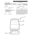
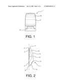
[0006]FIG. 1 is a top view of the belt clip of the present invention in the closed position.
[0007]FIG. 2 is an elevation view of the belt clip of the present invention in a closed position.
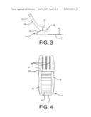
[0008]FIG. 3 is an elevation view of the belt clip of the present invention in the open position.
[0009]FIG. 4 is a top view of the belt clip of the present invention in the open position.
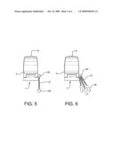
[0010]FIG. 5 is a top view of the belt clip of the present invention with a hanging ornament.
[0011]FIG. 6 is a top view of the belt clip of the present invention used to hang utilitarian items.
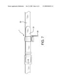
[0012]FIG. 7 is a view of the belt clip of the present invention in use on a belt.
DETAILED DESCRIPTION OF THE INVENTION
[0013]Belt clip 1 comprises planar base member 2 with lower end 4 and upper end 6 and vertically extending longitudinal axis 8. A plurality of teeth 24 extend from the upper surface of base 2. Connector element 10 extends outwardly from upper end 6 of base 2 and is rotatably attached, via connecting pin 12, to clamp unit 14. Clamp unit 14 comprises keeper plate 16 with laterally extending arms 18 and 20. Friction bar 22 is located between arms 18 and 20 and extends perpendicularly to longitudinal axis 8 of base 2. When belt clip 1 is closed, friction bar 22 is configured to directly contact the top surface of base 2 and the bottom surface of connector element 10, wedged in the position shown in FIG. 2. In this position, clamp unit 14 is tightly held against base 2 by the action of connector element 10 against friction bar 22. In the open position, shown in FIGS. 3 and 4, clamp unit 14 is raised above base 2, with friction bar 22 being freely rotatable, via connecting pin 12, over the base.
[0014]It is anticipated that, while not required, belt clip 1 optimally will have chain attachment ring 26, or equivalent connector device, permanently secured to lower end 4 of base 2. Chain or chains 27 hang down from ring 26 for attachment to ornamental charm 28, or various desired miscellaneous items 29, such as holders, lighters, keys, pen knives, etc.
[0015]In use, belt 30 is fastened to the wearer in the usual manner. Clamp unit 14 is placed in the raised position shown in FIGS. 3 and 4. Base 2 is slipped upward and behind, i.e. on the backside of, the body of belt 30. Terminus 32 of belt 30 is then placed on the top side of the body of belt 30. Keeper plate 16 is rotated upwards, around pin 12, down towards base 2. This forces friction bar 22 against and between base 2 and connector element 10, compelling keeper plate 16 tightly against belt terminus 32, thereby closing clamp unit 14. Teeth 24 assist in immoveably maintaining belt clip 1 in position in relation to belt 30.
[0016]Once belt clip 1 is attached to belt 30 and its terminus 32 is secured, hanging ornamental charm 28 can easily be seen or utilitarian items 29 can be hung from the clip.
[0017]To open clamp unit 14, keeper plate 16 is simply pulled outward by grasping its end 17. The downward rotational movement of keeper plate 16 compels friction bar 22 upward and off base 2, thus releasing terminus 32 so it can be freely removed from the body of belt 30.
[0018]Certain novel features and components of this invention are disclosed in detail in order to make the invention clear in at least one form thereof. However, it is to be clearly understood that the invention as disclosed is not necessarily limited to the exact form and details as disclosed, since it is apparent that various modifications and changes may be made without departing from the spirit of the invention.
User Contributions:
comments("1"); ?> comment_form("1"); ?>Inventors list |
Agents list |
Assignees list |
List by place |
Classification tree browser |
Top 100 Inventors |
Top 100 Agents |
Top 100 Assignees |
Usenet FAQ Index |
Documents |
Other FAQs |
User Contributions:
Comment about this patent or add new information about this topic:
Images included with this patent application:
 |  |
 |  |
 |
| New patent applications in this class: | |
| Date | Title |
|---|---|
| 2016-06-02 | Garment strap clip |
| 2016-05-26 | Parallel webbing attachment system |
| 2016-03-03 | Accessory fastening devices and methods |
| 2015-11-12 | Clip for securing a wearable item |
| 2015-05-28 | Adapter for protective head gear |
| Top Inventors for class "Buckles, buttons, clasps, etc." | |
| Rank | Inventor's name |
|---|---|
| 1 | Keiichi Keyaki |
| 2 | Andreas Hörtnagl |
| 3 | Toshio Iwahara |
| 4 | Joachim Fiedler |
| 5 | Allison S. Conner |