Patent application title: Assembly Comprising a Chassis and a Child Seat Being Detachably Connectable to the Chassis, Such a Chassis As Well As Such a Child Seat
Inventors:
Marc Mostert (Sittard, NL)
Paulus Adrianus Jacobus Van Diepen (Den Haag, NL)
Assignees:
COSCO MANAGEMENT, INC.
IPC8 Class: AB62B700FI
USPC Class:
280 4738
Class name: Wheeled stable vehicles, handle-propelled occupant seating type (e.g., baby carriages)
Publication date: 2009-10-15
Patent application number: 20090256323
chassis and a child seat being detachably
connectable to the chassis. The child seat is provided with at least one
first connecting element, which is detachably connectable to a second
connecting element provided in the chassis. The connecting elements are
provided with a locking mechanism for interlocking the connecting
elements. The locking mechanism can be unlocked for subsequently
disconnecting the connecting elements from each other. The locking
mechanism can be locked in a blocking position, in which position the
locking mechanism is unlocked.Claims:
1. An assembly comprising a chassis and a child seat being detachably
connectable to the chassis, which child seat is provided with at least
one first connecting element, which is detachably connectable to a second
connecting element provided in the chassis, said connecting elements
being provided with a locking mechanism for interlocking the connecting
elements, which locking mechanism can be unlocked for subsequently
disconnecting the connecting elements from each other, characterized in
that the locking mechanism can be locked in a blocking position, in which
position the locking mechanism is unlocked.
2. An assembly according to claim 1, characterized in the at the child seat is provided with first connecting elements located on two longitudinal sides, whilst the chassis is provided with two spaced-apart second connecting elements, which can be connected to said first connecting elements, and the locking mechanisms can be locked in the blocking positions in succession.
3. An assembly according to claim 1, characterized in that the first connecting element is provided with a pivot arm, which comprises at least a first and a second hook-shaped element, which elements mate with a first and a second pawl of the second connecting element, whilst the first hook-shaped element is connectable to the first pawl for locking the pivot arm in position and the second hook-shaped element is connectable to the second pawl for locking the pivot arm in the blocking position.
4. An assembly according to claim 2, characterized in that the first connecting element is provided with a pivot arm, which comprises at least a first and a second hook-shaped element, which elements mate with a first and a second pawl of the second connecting element, whilst the first hook-shaped element is connectable to the first pawl for locking the pivot arm in position and the second hook-shaped element is connectable to the second pawl for locking the pivot arm in the blocking position.
5. An assembly according to claim 3, characterized in that the second pawl comprises a part that extends conically from the first pawl.
6. An assembly according to claim 3, characterized in that the pivot arm is pivotable about a substantially horizontally extending pivot axis for connecting the pivot arm to the first pawl, whilst it is also pivotable about a substantially vertically extending second pivot axis for moving the pivot arm to the blocking position.
7. An assembly according to claim 5, characterized in that the pivot arm is pivotable about a substantially horizontally extending pivot axis for connecting the pivot arm to the first pawl, whilst it is also pivotable about a substantially vertically extending second pivot axis for moving the pivot arm to the blocking position.
8. An assembly according to claim 1, wherein the chassis is a stroller.Description:
[0001]Assembly comprising a chassis and a child seat being detachably
connectable to the chassis, such a chassis as well as such a child seat.
[0002]The invention relates to an assembly comprising a chassis and a child seat being detachably connectable to the chassis, which child seat is provided with at least one first connecting element, which is detachably connectable to a second connecting element provided in the chassis, said connecting elements being provided with a locking mechanism for interlocking the connecting elements, which locking mechanism can be unlocked for subsequently disconnecting the connecting elements from each other.
[0003]The invention also relates to a chassis and a child seat suitable for such an assembly.
[0004]In such an assembly, which is known from German utility model DE-U1-20.2005.008.211, a child seat is provided with two pin-shaped elements, which can each be positioned in tubular elements connected to the chassis. The tubular element is provided with a cam which is movable against spring force, which cam can be brought into engagement with a recess formed in said pin-shaped element for locking the child seat in position relative to the chassis.
[0005]As a result of said locking engagement of the child seat, the child seat is securely connected to the chassis. The chassis used in said German utility model is a stroller.
[0006]When a user wishes to remove the child seat from the stroller, the cams present on either side of the stroller must be simultaneously moved out of engagement with the recesses against spring force, after which the pin-shaped elements of the child seat can be lifted from the tubular elements. In order to do so, a user needs three hands, as it were, two for releasing the locking engagement on either side and one for lifting the child seat from the chassis.
[0007]Removing the child seat from the chassis is thus a comparatively complex operation.
[0008]The object of the invention is to provide an assembly which enables a user to remove the child seat from the chassis in a simple manner.
[0009]This object is accomplished with the assembly according to the invention in that the locking mechanism can be locked in a blocking position, in which position the locking mechanism is unlocked.
[0010]A user can move the locking mechanism to the blocking position with one hand, after which the child seat is still connected to the chassis but no longer interlocked with the chassis. The user will then no longer need that hand for holding the locking mechanism in the unlocked position, since the locking mechanism is in the blocking position. In other words, an external force is no longer needed for holding the locking mechanism in the unlocked position. After the locking mechanism has been unlocked and moved to the blocking position, the user has both hands available for disconnecting the child seat from the chassis.
[0011]In this way the serviceability of the assembly is enhanced. In addition, the safety of a child seated in the child seat is enhanced, since the user has both hands available for taking hold of the child seat. Furthermore, a user can unlock and disconnect the child seat from the chassis with one hand, if desired.
[0012]One embodiment of the assembly according to the invention is characterised in that the child seat is provided with first connecting elements located on two longitudinal sides, whilst the chassis is provided with two spaced-apart second connecting elements, which can be connected to said first connecting elements, and the locking mechanisms can be locked in the blocking positions in succession.
[0013]By using connecting elements provided on both longitudinal sides of the child seat, a secure connection with the chassis is obtained. Since the locking mechanisms can be moved to the blocking position in succession, a user can hold the child seat with one hand, whilst the user unlocks and blocks the locking mechanisms in succession with the other hand.
[0014]This enhances the safety of the child seated in the child seat.
[0015]Another embodiment of the assembly according to the invention is characterised in that the first connecting element is provided with a pivot arm, which comprises at least a first and a second hook-shaped element, which elements mate with a first and a second pawl of the second connecting element, whilst the first hook-shaped element is connectable to the first pawl for locking the pivot arm in position and the second hook-shaped element is connectable to the second pawl for locking the pivot arm in the blocking position.
[0016]In this way connecting, locking, unlocking and blocking are realised in a simple manner.
[0017]Yet another embodiment of the assembly according to the invention is characterised in that the second pawl comprises a part that extends conically from the first pawl.
[0018]Such a pawl is comparatively easy to produce.
[0019]Another embodiment of the invention is characterised in that the pivot arm is pivotable about a substantially horizontally extending pivot axis for connecting the pivot arm to the first pawl, whilst it is also pivotable about a substantially vertically extending second pivot axis for moving the pivot arm to the blocking position.
[0020]Since the pivot arm is pivotable both about a substantially horizontally extending pivot axis and about a substantially vertically extending pivot axis, different kinds of movement of the pivot arm can be realised in a simple manner.
[0021]The invention will now be explained in more detail with reference to the drawing, in which:
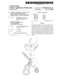
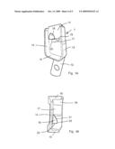
[0022]FIG. 1 is a perspective view of a child seat connected to a stroller;
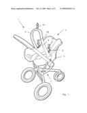
[0023]FIG. 2 is a perspective view of a child seat disconnected from the stroller;
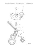
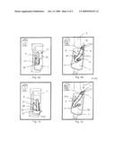
[0024]FIG. 3 is a side view of the child seat shown in FIG. 2;
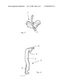
[0025]FIG. 4 is a larger-scale detail view of the pivot arm of the child seat of FIG. 3;
[0026]FIGS. 5a and 5b are a perspective side view and a perspective top plan view, respectively, of the second connecting element of the stroller shown in FIGS. 1 and 2;
[0027]FIGS. 6a and 6b are a perspective top plan view and a perspective side view, respectively, of interlocked first and second connecting elements;
[0028]FIGS. 7a and 7b are a perspective top plan view and a perspective side view, respectively, of interconnected connecting elements, with the locking mechanism being locked in a blocking position.
[0029]Like parts are indicated by the same numerals in the figures.
[0030]FIGS. 1 and 2 show an assembly 1 according to the invention, which comprises a stroller 2 forming a chassis and a child seat 3 detachably connected to the stroller 2. The child seat 3 comprises a seat portion 4 and a carrying handle 5, which is connected to the seat portion 4 on either side of the seat portion 4. Such a child seat 3 is known per se and will not be explained in more detail herein, therefore. On both longitudinal sides, the child seat 3 is provided with first connecting elements 6, which mate with second connecting elements 7 provided in the stroller 2.
[0031]The first and second connecting elements 6, 7 and the operation thereof will be explained in more detail with reference FIGS. 3-7b.
[0032]FIG. 3 is a side view of the child seat 3 with the first connecting element 6 illustrated in dotted lines.
[0033]As FIG. 4 clearly shows, the first connecting element 6 comprises an elongated pivot arm 9 which is pivotable about a horizontally extending pivot axis 8, which pivot arm is provided, at a first end thereof, with a control knob 10, which can be operated on a side of the child seat 3 that faces the carrying handle 5. The pivot arm 9 is provided with a first hook-shaped element 11 at a second end located on a side remote from said first end and also with an elongated rib 12, which extends transversely to the pivot arm 9. The rib 12 forms a second hook-shaped element.
[0034]FIGS. 5a and 5b are a perspective side view and a perspective top plan view, respectively, of the second connecting element 7, which is connected to a rod 13 of the frame of the stroller 2. The second connecting element 7 comprises a carrier plate 14 and two side walls 15 extending transversely to the carrier plate 14. The side walls 15 are interconnected at a bottom side by a side wall 16 extending substantially transversely thereto. The carrier plate 14 is furthermore provided with two pawls 17, 18. The first pawl 17 has a downwardly inclined surface 19 and an engagement surface that faces towards the side wall 16. The surfaces 19 and 20 extend transversely to the carrier plate 14.
[0035]The second pawl 18 comprises a part 21 that extends conically from the first pawl 17, which part merges into a wall 23 extending substantially transversely to the carrier plate 14 via a sharp transition 22 on a side remote from the first pawl 17. The wall 23 extends substantially vertically.
[0036]The operation of the connecting elements 6, 7 will now be discussed in more detail with reference to FIGS. 6a-7b.
[0037]Upon placement of the child seat 3 on the stroller 2 forming a chassis, the first connecting elements 6 present on either side of the child seat 3 are placed between the side walls 15 of the second connecting elements 7. During said placement, the underside of the first hook-shaped element 11 slides over the wall part 19, whilst the pivot arm 9 is pivoted in a direction indicated by the arrow P11 against spring force until the hook-shaped element 11 has moved over the entire part 19 and engages the engagement surface 20 of the first hook-shaped element 17 under spring force. The first connecting element 6 is now interlocked with the second connecting element 7 by the first hook-shaped element 11, which is in engagement with the engagement surface 20. The child seat 3 is now securely connected to the stroller 2 and cannot undesirably become detached therefrom.
[0038]When a user wishes to remove the child seat 3 from the stroller 2, for example for using the child seat 3 as a separate child seat or using it in a vehicle, for example a car, the user will take hold of the carrying handle 5 with one hand. The user will push the control knob 10 in the direction indicated by the arrow P1 (see FIGS. 1 and 7b) with the other hand, causing the pivot arm 9 to pivot in the direction indicated by the arrow P11 about the pivot axis 8, resulting in the first hook-shaped element 11 being disconnected from the engagement surface 20. During said pivoting of the pivot arm 9 about the pivot axis 8, the pivot arm 9 will also rotate in the direction indicated by the arrow P12 about a vertically extending axis of rotation. Said rotation takes place in that the pivot arm 9 is moved over the conically extending part 21. The pivot arm 9 is pivoted in the direction indicated by the arrows P11, P12 until the rib 12 is located beyond the transition 22 of the conically extending part 21 and is moved in the opposite direction of the arrow P12 under spring force, with the rib 12 abutting against the wall 23. The pivot arm 9 now takes up a blocking position, in which the pivot arm 9 of the first pawl 17 of the second connecting element 7 is unlocked.
[0039]After the pivot arm 9 located on one longitudinal side of the child seat 3 has been unlocked and blocked, the user will operate the pivot arm 9 located on the other longitudinal side by moving the control knob 10 in the direction indicated by the arrow P2. After the rib 12 of this pivot arm 9 has been moved into engagement with the associated wall 23 as well, the child seat 3 can be lifted from the stroller 2 in the direction indicated by the arrow P3.
[0040]If the control knob 10 is depressed only little, so that the rib 12 is not moved past the transition 22 of the conically extending part 21, the first hook-shaped element 11 of the pivot arm 9 will be moved into engagement with the engagement surface 20 again under spring force.
[0041]The pivot arm 9 is pivotable in the direction indicated by the arrow P11 about the pivot axis 8 with some play, as a result of which the pivot arm 9 is at the same time rotatable in the direction indicated by the arrow P12 through an angle large enough for moving the pivot arm 9 over the conically extending part 21.
Claims:
1. An assembly comprising a chassis and a child seat being detachably
connectable to the chassis, which child seat is provided with at least
one first connecting element, which is detachably connectable to a second
connecting element provided in the chassis, said connecting elements
being provided with a locking mechanism for interlocking the connecting
elements, which locking mechanism can be unlocked for subsequently
disconnecting the connecting elements from each other, characterized in
that the locking mechanism can be locked in a blocking position, in which
position the locking mechanism is unlocked.
2. An assembly according to claim 1, characterized in the at the child seat is provided with first connecting elements located on two longitudinal sides, whilst the chassis is provided with two spaced-apart second connecting elements, which can be connected to said first connecting elements, and the locking mechanisms can be locked in the blocking positions in succession.
3. An assembly according to claim 1, characterized in that the first connecting element is provided with a pivot arm, which comprises at least a first and a second hook-shaped element, which elements mate with a first and a second pawl of the second connecting element, whilst the first hook-shaped element is connectable to the first pawl for locking the pivot arm in position and the second hook-shaped element is connectable to the second pawl for locking the pivot arm in the blocking position.
4. An assembly according to claim 2, characterized in that the first connecting element is provided with a pivot arm, which comprises at least a first and a second hook-shaped element, which elements mate with a first and a second pawl of the second connecting element, whilst the first hook-shaped element is connectable to the first pawl for locking the pivot arm in position and the second hook-shaped element is connectable to the second pawl for locking the pivot arm in the blocking position.
5. An assembly according to claim 3, characterized in that the second pawl comprises a part that extends conically from the first pawl.
6. An assembly according to claim 3, characterized in that the pivot arm is pivotable about a substantially horizontally extending pivot axis for connecting the pivot arm to the first pawl, whilst it is also pivotable about a substantially vertically extending second pivot axis for moving the pivot arm to the blocking position.
7. An assembly according to claim 5, characterized in that the pivot arm is pivotable about a substantially horizontally extending pivot axis for connecting the pivot arm to the first pawl, whilst it is also pivotable about a substantially vertically extending second pivot axis for moving the pivot arm to the blocking position.
8. An assembly according to claim 1, wherein the chassis is a stroller.
Description:
[0001]Assembly comprising a chassis and a child seat being detachably
connectable to the chassis, such a chassis as well as such a child seat.
[0002]The invention relates to an assembly comprising a chassis and a child seat being detachably connectable to the chassis, which child seat is provided with at least one first connecting element, which is detachably connectable to a second connecting element provided in the chassis, said connecting elements being provided with a locking mechanism for interlocking the connecting elements, which locking mechanism can be unlocked for subsequently disconnecting the connecting elements from each other.
[0003]The invention also relates to a chassis and a child seat suitable for such an assembly.
[0004]In such an assembly, which is known from German utility model DE-U1-20.2005.008.211, a child seat is provided with two pin-shaped elements, which can each be positioned in tubular elements connected to the chassis. The tubular element is provided with a cam which is movable against spring force, which cam can be brought into engagement with a recess formed in said pin-shaped element for locking the child seat in position relative to the chassis.
[0005]As a result of said locking engagement of the child seat, the child seat is securely connected to the chassis. The chassis used in said German utility model is a stroller.
[0006]When a user wishes to remove the child seat from the stroller, the cams present on either side of the stroller must be simultaneously moved out of engagement with the recesses against spring force, after which the pin-shaped elements of the child seat can be lifted from the tubular elements. In order to do so, a user needs three hands, as it were, two for releasing the locking engagement on either side and one for lifting the child seat from the chassis.
[0007]Removing the child seat from the chassis is thus a comparatively complex operation.
[0008]The object of the invention is to provide an assembly which enables a user to remove the child seat from the chassis in a simple manner.
[0009]This object is accomplished with the assembly according to the invention in that the locking mechanism can be locked in a blocking position, in which position the locking mechanism is unlocked.
[0010]A user can move the locking mechanism to the blocking position with one hand, after which the child seat is still connected to the chassis but no longer interlocked with the chassis. The user will then no longer need that hand for holding the locking mechanism in the unlocked position, since the locking mechanism is in the blocking position. In other words, an external force is no longer needed for holding the locking mechanism in the unlocked position. After the locking mechanism has been unlocked and moved to the blocking position, the user has both hands available for disconnecting the child seat from the chassis.
[0011]In this way the serviceability of the assembly is enhanced. In addition, the safety of a child seated in the child seat is enhanced, since the user has both hands available for taking hold of the child seat. Furthermore, a user can unlock and disconnect the child seat from the chassis with one hand, if desired.
[0012]One embodiment of the assembly according to the invention is characterised in that the child seat is provided with first connecting elements located on two longitudinal sides, whilst the chassis is provided with two spaced-apart second connecting elements, which can be connected to said first connecting elements, and the locking mechanisms can be locked in the blocking positions in succession.
[0013]By using connecting elements provided on both longitudinal sides of the child seat, a secure connection with the chassis is obtained. Since the locking mechanisms can be moved to the blocking position in succession, a user can hold the child seat with one hand, whilst the user unlocks and blocks the locking mechanisms in succession with the other hand.
[0014]This enhances the safety of the child seated in the child seat.
[0015]Another embodiment of the assembly according to the invention is characterised in that the first connecting element is provided with a pivot arm, which comprises at least a first and a second hook-shaped element, which elements mate with a first and a second pawl of the second connecting element, whilst the first hook-shaped element is connectable to the first pawl for locking the pivot arm in position and the second hook-shaped element is connectable to the second pawl for locking the pivot arm in the blocking position.
[0016]In this way connecting, locking, unlocking and blocking are realised in a simple manner.
[0017]Yet another embodiment of the assembly according to the invention is characterised in that the second pawl comprises a part that extends conically from the first pawl.
[0018]Such a pawl is comparatively easy to produce.
[0019]Another embodiment of the invention is characterised in that the pivot arm is pivotable about a substantially horizontally extending pivot axis for connecting the pivot arm to the first pawl, whilst it is also pivotable about a substantially vertically extending second pivot axis for moving the pivot arm to the blocking position.
[0020]Since the pivot arm is pivotable both about a substantially horizontally extending pivot axis and about a substantially vertically extending pivot axis, different kinds of movement of the pivot arm can be realised in a simple manner.
[0021]The invention will now be explained in more detail with reference to the drawing, in which:
[0022]FIG. 1 is a perspective view of a child seat connected to a stroller;
[0023]FIG. 2 is a perspective view of a child seat disconnected from the stroller;
[0024]FIG. 3 is a side view of the child seat shown in FIG. 2;
[0025]FIG. 4 is a larger-scale detail view of the pivot arm of the child seat of FIG. 3;
[0026]FIGS. 5a and 5b are a perspective side view and a perspective top plan view, respectively, of the second connecting element of the stroller shown in FIGS. 1 and 2;
[0027]FIGS. 6a and 6b are a perspective top plan view and a perspective side view, respectively, of interlocked first and second connecting elements;
[0028]FIGS. 7a and 7b are a perspective top plan view and a perspective side view, respectively, of interconnected connecting elements, with the locking mechanism being locked in a blocking position.
[0029]Like parts are indicated by the same numerals in the figures.
[0030]FIGS. 1 and 2 show an assembly 1 according to the invention, which comprises a stroller 2 forming a chassis and a child seat 3 detachably connected to the stroller 2. The child seat 3 comprises a seat portion 4 and a carrying handle 5, which is connected to the seat portion 4 on either side of the seat portion 4. Such a child seat 3 is known per se and will not be explained in more detail herein, therefore. On both longitudinal sides, the child seat 3 is provided with first connecting elements 6, which mate with second connecting elements 7 provided in the stroller 2.
[0031]The first and second connecting elements 6, 7 and the operation thereof will be explained in more detail with reference FIGS. 3-7b.
[0032]FIG. 3 is a side view of the child seat 3 with the first connecting element 6 illustrated in dotted lines.
[0033]As FIG. 4 clearly shows, the first connecting element 6 comprises an elongated pivot arm 9 which is pivotable about a horizontally extending pivot axis 8, which pivot arm is provided, at a first end thereof, with a control knob 10, which can be operated on a side of the child seat 3 that faces the carrying handle 5. The pivot arm 9 is provided with a first hook-shaped element 11 at a second end located on a side remote from said first end and also with an elongated rib 12, which extends transversely to the pivot arm 9. The rib 12 forms a second hook-shaped element.
[0034]FIGS. 5a and 5b are a perspective side view and a perspective top plan view, respectively, of the second connecting element 7, which is connected to a rod 13 of the frame of the stroller 2. The second connecting element 7 comprises a carrier plate 14 and two side walls 15 extending transversely to the carrier plate 14. The side walls 15 are interconnected at a bottom side by a side wall 16 extending substantially transversely thereto. The carrier plate 14 is furthermore provided with two pawls 17, 18. The first pawl 17 has a downwardly inclined surface 19 and an engagement surface that faces towards the side wall 16. The surfaces 19 and 20 extend transversely to the carrier plate 14.
[0035]The second pawl 18 comprises a part 21 that extends conically from the first pawl 17, which part merges into a wall 23 extending substantially transversely to the carrier plate 14 via a sharp transition 22 on a side remote from the first pawl 17. The wall 23 extends substantially vertically.
[0036]The operation of the connecting elements 6, 7 will now be discussed in more detail with reference to FIGS. 6a-7b.
[0037]Upon placement of the child seat 3 on the stroller 2 forming a chassis, the first connecting elements 6 present on either side of the child seat 3 are placed between the side walls 15 of the second connecting elements 7. During said placement, the underside of the first hook-shaped element 11 slides over the wall part 19, whilst the pivot arm 9 is pivoted in a direction indicated by the arrow P11 against spring force until the hook-shaped element 11 has moved over the entire part 19 and engages the engagement surface 20 of the first hook-shaped element 17 under spring force. The first connecting element 6 is now interlocked with the second connecting element 7 by the first hook-shaped element 11, which is in engagement with the engagement surface 20. The child seat 3 is now securely connected to the stroller 2 and cannot undesirably become detached therefrom.
[0038]When a user wishes to remove the child seat 3 from the stroller 2, for example for using the child seat 3 as a separate child seat or using it in a vehicle, for example a car, the user will take hold of the carrying handle 5 with one hand. The user will push the control knob 10 in the direction indicated by the arrow P1 (see FIGS. 1 and 7b) with the other hand, causing the pivot arm 9 to pivot in the direction indicated by the arrow P11 about the pivot axis 8, resulting in the first hook-shaped element 11 being disconnected from the engagement surface 20. During said pivoting of the pivot arm 9 about the pivot axis 8, the pivot arm 9 will also rotate in the direction indicated by the arrow P12 about a vertically extending axis of rotation. Said rotation takes place in that the pivot arm 9 is moved over the conically extending part 21. The pivot arm 9 is pivoted in the direction indicated by the arrows P11, P12 until the rib 12 is located beyond the transition 22 of the conically extending part 21 and is moved in the opposite direction of the arrow P12 under spring force, with the rib 12 abutting against the wall 23. The pivot arm 9 now takes up a blocking position, in which the pivot arm 9 of the first pawl 17 of the second connecting element 7 is unlocked.
[0039]After the pivot arm 9 located on one longitudinal side of the child seat 3 has been unlocked and blocked, the user will operate the pivot arm 9 located on the other longitudinal side by moving the control knob 10 in the direction indicated by the arrow P2. After the rib 12 of this pivot arm 9 has been moved into engagement with the associated wall 23 as well, the child seat 3 can be lifted from the stroller 2 in the direction indicated by the arrow P3.
[0040]If the control knob 10 is depressed only little, so that the rib 12 is not moved past the transition 22 of the conically extending part 21, the first hook-shaped element 11 of the pivot arm 9 will be moved into engagement with the engagement surface 20 again under spring force.
[0041]The pivot arm 9 is pivotable in the direction indicated by the arrow P11 about the pivot axis 8 with some play, as a result of which the pivot arm 9 is at the same time rotatable in the direction indicated by the arrow P12 through an angle large enough for moving the pivot arm 9 over the conically extending part 21.
User Contributions:
Comment about this patent or add new information about this topic:
| People who visited this patent also read: | |
| Patent application number | Title |
|---|---|
| 20120316567 | SYSTEMS AND METHODS FOR JOINT REPLACEMENT |
| 20120316566 | Biologic Vertebral Reconstruction |
| 20120316565 | TOOLS FOR PERFORMING LESS INVASIVE ORTHOPEDIC JOINT PROCEDURES |
| 20120316564 | DRILL GUIDES FOR CONFIRMING ALIGNMENT OF PATIENT-SPECIFIC ALIGNMENT GUIDES |
| 20120316563 | BI-CRUCIATE KNEE SYSTEM |
Images included with this patent application:
 |  |
 |  |
 |  |
| New patent applications in this class: | |
| Date | Title |
|---|---|
| 2016-12-29 | Wheelchair with a waste disposal system |
| 2016-09-01 | Walker apparatus and backrest therefor |
| 2016-04-28 | Infant carrier transport |
| 2016-01-14 | Baby stroller lighting system |
| 2016-01-07 | Infant stroller apparatus |
| New patent applications from these inventors: | |
| Date | Title |
|---|---|
| 2010-05-20 | Child vehicle seat |
| Top Inventors for class "Land vehicles" | |
| Rank | Inventor's name |
|---|---|
| 1 | Osamu Fukawatase |
| 2 | Christopher P. D'Aluisio |
| 3 | Richard W. Mccoy |
| 4 | Jun Yeol Choi |
| 5 | Yusuke Fujiwara |