Patent application title: Compact storage unit
Inventors:
Gloria J. Rabbit (Inola, OK, US)
IPC8 Class: AB65D2504FI
USPC Class:
220507
Class name: Receptacles compartmented container cells (i.e., identical or similar compartments each intended to hold a single item)
Publication date: 2009-10-15
Patent application number: 20090255936
Inventors list |
Agents list |
Assignees list |
List by place |
Classification tree browser |
Top 100 Inventors |
Top 100 Agents |
Top 100 Assignees |
Usenet FAQ Index |
Documents |
Other FAQs |
Patent application title: Compact storage unit
Inventors:
Gloria J. Rabbit
Agents:
LITMAN LAW OFFICES, LTD.
Assignees:
Origin: ARLINGTON, VA US
IPC8 Class: AB65D2504FI
USPC Class:
220507
Patent application number: 20090255936
Abstract:
The compact storage unit includes a case having front, rear, top, bottom
and opposing side walls made of hard plastic, preferably by injection
molding. The case has a substantially rectangular or substantially square
cross section. The front wall folds up and snaps shut on the top wall.
The case houses a plurality of plastic slide trays. The trays are also
made of hard plastic. Each tray supports a plurality of storage
containers, each storage container having a plurality of bins, each bin
having an individual snap lid. The trays slide out revealing the
containers for easy access. A lip extends upward from the rear edge of
the tray to engage the containers so that the containers are drawn out of
the case when the tray is pulled out.Claims:
1. A compact storage unit, comprising:a case defining an enclosure, the
case having front, rear, bottom, top, and opposing side walls, the front
wall being pivotally attached to the bottom wall;opposing pair of ribs
extending from the opposing sidewalls, the pairs of ribs defining grooves
extending from front to back of the enclosure, the grooves being spaced
apart and aligned vertically;a plurality of trays slidable in the
grooves; anda plurality of elongate storage containers supported
side-by-side on each of the trays.
2. The compact storage unit according to claim 1, wherein each said storage container has a plurality of partition walls dividing the storage container into a plurality of storage compartments.
3. The compact storage unit according to claim 2, wherein each said storage compartment has a lid pivotally attached thereto, the storage compartment lids being independently operable to provide independent access to each said individual storage compartment.
4. The compact storage unit according to claim 1, further comprising a living hinge pivotally attaching each said lid to its corresponding said storage container.
5. The compact storage unit according to claim 1, wherein each said tray comprises a planar member extending between the opposing sidewalls of said case and between the front and back walls of said case, each said tray having a rear edge and a lip extending upwardly across the rear edge, the storage containers mounted on each said tray bearing against the lip when the tray is pulled forward from said case.
6. The compact storage unit according to claim 1, further comprising a flap pivotally extending from the front wall and mating snap fasteners disposed on the flap and the top wall, whereby the flap is foldable onto the top wall, the snap fasteners mating to fasten the front wall in a closed position.
7. A compact storage unit, comprising:a case defining an enclosure having an open front and a pair of sidewalls having a plurality of vertically aligned, spaced apart tracks disposed thereon;a front wall pivotally attached to the case, the front wall being pivotal upward to close the open front of the enclosure;a latch extending from the front wall, the latch being removably fastened to the enclosure;a plurality of trays slidably mounted on the tracks; anda plurality of elongate storage containers supported side-by-side on the trays, each of the trays having a plurality of storage containers supported thereon, each of the storage containers having partition walls dividing the storage containers into a plurality of storage compartments, each of the storage compartments having an independently operable lid and a living hinge pivotally attaching the lid to the corresponding storage container.
8. The compact storage unit according to claim 7, wherein said case, said front wall said trays, and said storage containers are all made from plastic.
Description:
CROSS-REFERENCE TO RELATED APPLICATION
[0001]This application claims the benefit of U.S. Provisional Patent Application Ser. No. 61/045,096, filed Apr. 15, 2008.
BACKGROUND OF THE INVENTION
[0002]1. Field of the Invention
[0003]The present invention relates to storage cases, and particularly to a compact storage unit for small items, such as arts and crafts items, hobby kit items, sewing notions, hardware (nuts, bolts, etc.), and the like.
[0004]2. Description of the Related Art
[0005]Craft keepers are organizers that arts and craft people use to organize and store their craft items. Many arts and craft people have felt that there must be a better way to keep their arts and craft items, since most of the time, numerous craft keepers must be utilized to put away the many items that the arts and craft person may wish to store. For example, a typical craft keeper may have seventeen large compartments that are generally too large for the storage of small items. It may take forty-seven craft keepers to have seven hundred ninety-nine compartments. Due to the large size of craft keepers, a considerable dedicated space is required to accommodate forty-seven craft keepers. Moreover, forty-seven craft keepers may be very expensive at approximately three dollars per unit.
[0006]There are many other occasions in which it is necessary or desirable to store small items or small parts. Electrical or electronics hobbyists often must deal with small connectors and small electrical components (diodes, integrated circuits, resistors, capacitors, etc.), and like to have spare components at hand. Woodworkers and machinists frequently need to have screw, nuts, bolts, and other hardware items of various sizes on hand. While it is possible to store such small items in individual tins or other containers, typically such containers become separated, lost, or misplaced so that one can never lay one's hand on the desired component quickly.
[0007]Thus, a compact storage unit solving the aforementioned problems is desired.
SUMMARY OF THE INVENTION
[0008]The compact storage unit includes a case having front, rear, top, bottom and opposing side walls made of hard plastic, preferably by injection molding. The case has a substantially rectangular or substantially square cross section. The front wall folds up and snaps shut on the top wall. The case houses a plurality of plastic slide trays. The trays are also made of hard plastic. Each tray supports a plurality of storage containers, each storage container having a plurality of bins, each bin having an individual snap lid. The trays slide out revealing the containers for easy access. A lip extends upward from the rear edge of the tray to engage the containers so that the containers are drawn out of the case when the tray is pulled out.
[0009]These and other features of the present invention will become readily apparent upon further review of the following specification and drawings.
BRIEF DESCRIPTION OF THE DRAWINGS
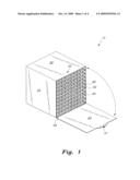
[0010]FIG. 1 is an environmental, perspective view of a compact storage unit according to the present invention.
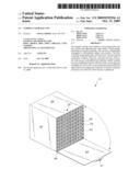
[0011]FIG. 2 is an exploded perspective view of the compact storage unit according to the present invention.
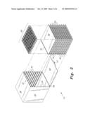
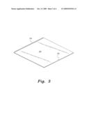
[0012]FIG. 3 is a perspective view of the tray of a compact storage unit according to the present invention.
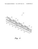
[0013]FIG. 4 is a perspective view of a storage container for a compact storage unit according to the present invention.
[0014]Similar reference characters denote corresponding features consistently throughout the attached drawings.
DETAILED DESCRIPTION OF THE PREFERRED EMBODIMENT
[0015]As shown in FIGS. 1 and 2, the compact storage unit 10 includes a box-shaped case having a front wall 63, a top wall 30, opposing sidewalls 20, a bottom wall, and a rear wall defining an enclosure. The case may be made of hard plastic, preferably by injection molding. The front wall 63 is pivotally attached to the front edge of the bottom wall by a hinge 69, which may be a living hinge, so that the front wall 63 covers the open front of the case. A flap or latch extends from the top edge of the front wall 63. The flap is also pivotal, and has a snap member 67, such as a button, on one face thereof. The flap may be folded over the front edge of the top wall 20, and snap member 67 may mate with a corresponding snap member 33, such as an aperture, defined in or mounted on top of the top wall 20. A handle may be mounted on the top wall, if desired.
[0016]The case defines a hollow interior. Each sidewall 20 has pairs of ribs 40 that extend from front to back of the interior of the case, each pair of ribs 40 defining a groove, the grooves on opposite sides of the case being aligned. The grooves serves as guides or tracks to support a plurality of trays 50 that are slidable in the grooves. Preferably, there are about ten pairs of vertically aligned ribs 40 to support a corresponding ten trays 50. The trays 50 may also be made of hard plastic. As shown in FIG. 3, each tray 50 is planar, having a lip 54 extending upwardly across its rear edge. Each tray 50 may also have an aperture 52 defined therein adjacent its front edge to support a string or other flexible member that can be attached to the tray 50 to aid in pulling the tray 50 out of the case.
[0017]Each tray 50 supports a plurality of storage containers 60. As shown in FIG. 4, each storage container 60 is an elongate, narrow box having opposing sidewalls 80 and end walls 82. A plurality of partition walls 84 divide each storage container 60 into a plurality of bins or compartments, which are dimensioned and configured for storing small items. Each compartment has its own individual lid having a rear edge 65 pivotally attached to one of the sidewalls, preferably by a living hinge 70, and a front flange 75 that forms a friction fit with the opposing sidewall 80. Each storage container 60 has a length that extends from front to back of the tray 50, the rear of the storage container 60 bearing against lip 54 when the tray 50 is pulled forward in the case. The width of the end walls is dimensioned so that ten storage containers 60 may fit side-by-side on each tray 50.
[0018]The trays 50 slide out, providing access to the containers 60 and the storage compartments defined therein. The compact storage unit 10 may store up to approximately 800 small items, such as eyelets and brads used in scrap booking craft, buttons, embellishments, and the like.
[0019]It is to be understood that the present invention is not limited to the embodiment described above, but encompasses any and all embodiments within the scope of the following claims.
User Contributions:
comments("1"); ?> comment_form("1"); ?>Inventors list |
Agents list |
Assignees list |
List by place |
Classification tree browser |
Top 100 Inventors |
Top 100 Agents |
Top 100 Assignees |
Usenet FAQ Index |
Documents |
Other FAQs |
User Contributions:
Comment about this patent or add new information about this topic:
Images included with this patent application:
 |  |
 |  |
 |
| Similar patent applications: | |
| Date | Title |
|---|---|
| 2011-08-25 | Compressed gas storage unit |
| 2012-02-16 | Decorative paper plate storage units |
| 2009-08-20 | Shopping bag storage and dispensing unit |
| 2012-08-02 | Particulate material storage and delivery system |
| 2009-07-23 | Combination storage device |
| New patent applications in this class: | |
| Date | Title |
|---|---|
| 2015-11-26 | High strength partition box assembly |
| 2014-10-09 | Product packaging |
| 2014-09-18 | Divider boxes and their assembly |
| 2014-07-24 | Cartridge and multicomponent cartridge |
| 2014-04-10 | "pill caddy" "container caddy" |
| Top Inventors for class "Receptacles" | |
| Rank | Inventor's name |
|---|---|
| 1 | Daniel Lee Bizzell |
| 2 | Frank Yang |
| 3 | Terry Vovan |
| 4 | William P. Apps |
| 5 | Lowell L. Wood, Jr. |