Patent application title: Systems, devices, and/or methods for recuperating energy and/or particulates
Inventors:
Josef Fercher (Graz, AT)
Bernhard Fercher (Graz, AT)
Assignees:
Nettek International
IPC8 Class: AF01N302FI
USPC Class:
60311
Class name: Power plants internal combustion engine with treatment or handling of exhaust gas by sorber or mechanical separator
Publication date: 2009-10-01
Patent application number: 20090241525
Inventors list |
Agents list |
Assignees list |
List by place |
Classification tree browser |
Top 100 Inventors |
Top 100 Agents |
Top 100 Assignees |
Usenet FAQ Index |
Documents |
Other FAQs |
Patent application title: Systems, devices, and/or methods for recuperating energy and/or particulates
Inventors:
Josef Fercher
Bernhard Fercher
Agents:
Zobrist Law Group
Assignees:
Nettek International
Origin: CHARLOTTESVILLE, VA US
IPC8 Class: AF01N302FI
USPC Class:
60311
Patent application number: 20090241525
Abstract:
Certain exemplary embodiments provide an energy and particle recuperator
(EPR) for dirty gas fluids and/or gas solids fluid mixes. Gas fluids
and/or gas solids fluid mixes stream through a vessel. Heat contained in
the gas fluids and/or gas solid fluid mixes is partially transferred to a
liquid spray fluid sprayed inside the vessel. Heat is transferred from
the liquid to a clean process fluid via a heat exchanger.Claims:
1. A system, comprising:an energy and particle recuperator adapted to
process a gas fluid, said energy and particle recuperator comprising a
substantially hollow body, said substantially hollow body having a
substantially cylindrical portion, said substantially cylindrical portion
defining a central longitudinal axis, said energy and particle
recuperator comprising a gas inlet, said central longitudinal axis
substantially perpendicular to a primary direction of flow of said gas
fluid through said gas inlet, a set of nozzles adapted to spray a liquid
into said energy and particle recuperator, liquid sprayed via said set of
nozzles adapted to collect particulates entrained in said gas fluid, said
liquid sprayed via said set of nozzles adapted to receive heat energy
from said gas fluid, said energy and particle recuperator defining a heat
exchange fluid channel with serrated surfaces, said heat exchange fluid
channel substantially surrounding at least a portion of said
substantially cylindrical portion of said energy and particle
recuperator, said heat exchange fluid channel adapted to receive a heat
transfer fluid, said energy and particle recuperator adapted to cause
heat energy to be transferred from said gas fluid to said heat transfer
fluid without said heat transfer fluid directly contacting said gas
fluid.
2. The system of claim 1, further comprising:said set of nozzles.
3. The system of claim 1, further comprising:a heat exchanger adapted to receive said liquid sprayed via said set of nozzles, said heat exchanger adapted to transfer heat energy from said liquid sprayed via said set of nozzles to a clean process fluid.
4. The system of claim 1, further comprising:a heat exchanger adapted to transfer heat energy from said liquid sprayed via said set of nozzles to a clean process fluid, said heat exchanger comprising a set of pipes, each of said set of pipes defining a longitudinal axis, each of said set of longitudinal axes substantially parallel, each of said set of pipes comprising a substantially planar surface over at least a portion of a pipe length so as to partially define a channel between each pair of adjacent pipes of said set of pipes, a cross-section of each pipe at said portion of said pipe length comprising a pair of substantially parallel opposing planar sides with at least one rounded edge, each of said set of pipes comprising ends having a substantially circular cross-section, each of said set of pipes comprising fins.
5. The system of claim 1, further comprising:a heat exchanger adapted to transfer heat energy from said liquid sprayed via said set of nozzles to a clean process fluid, said heat exchanger comprising a set of pipes, each of said set of pipes defining a longitudinal axis, each of said set of longitudinal axes substantially parallel, each of said set of pipes comprising a substantially planar surface over at least a portion of a pipe length so as to partially define a channel between each pair of adjacent pipes of said set of pipes, a cross-section of each pipe at said portion of said pipe length comprising a pair of substantially parallel opposing planar sides with at least one rounded edge, each of said set of pipes comprising ends having a substantially circular cross-section, each of said set of pipes comprising dimples.
6. The system of claim 1, further comprising:a heat exchanger adapted to transfer heat energy from said liquid sprayed via said set of nozzles to a clean process fluid, said heat exchanger comprising a set of pipes, each of said set of pipes defining a longitudinal axis, each of said set of longitudinal axes substantially parallel, each of said set of pipes comprising a substantially planar surface over at least a portion of a pipe length so as to partially define a channel between each pair of adjacent pipes of said set of pipes, each channel interrupted by connection areas between pairs of adjacent pipes, a cross-section of each pipe at said portion of said pipe length comprising a pair of substantially parallel opposing planar sides with at least one rounded edge, each of said set of pipes comprising ends having a substantially circular cross-section, each of said set of pipes comprising dimples.
7. The system of claim 1, further comprising:a heat exchanger adapted to transfer heat energy from said liquid sprayed via said set of nozzles to a clean process fluid, said heat exchanger comprising a set of pipes, each of said set of pipes defining a longitudinal axis, each of said set of longitudinal axes substantially parallel, each of said set of pipes comprising a substantially planar surface over at least a portion of a pipe length so as to partially define a channel between each pair of adjacent pipes of said set of pipes, each channel interrupted by connection areas between pairs of adjacent pipes, each connection area defining a substantially rhombic shape, a cross-section of each pipe at said portion of said pipe length comprising a pair of substantially parallel opposing planar sides with at least one rounded edge, each of said set of pipes comprising ends having a substantially circular cross-section, each of said set of pipes comprising dimples.
8. The system of claim 1, further comprising:a heat exchanger adapted to transfer heat energy from said liquid sprayed via said set of nozzles to a clean process fluid, said heat exchanger comprising a set of pipes, each of said set of pipes defining a longitudinal axis, each of said set of longitudinal axes substantially parallel, each of said set of pipes comprising a substantially planar surface over at least a portion of a pipe length so as to partially define a serpentine channel between each pair of adjacent pipes of said set of pipes, a cross-section of each pipe at said portion of said pipe length comprising a pair of substantially parallel opposing planar sides with at least one rounded end, each of said set of pipes comprising ends having a substantially circular cross-section, each of said set of pipes comprising dimples.
9. The system of claim 1, further comprising:a particle separator adapted to remove said particulates from said liquid sprayed via said set of nozzles.
10. The system of claim 1, further comprising:a pump adapted to cause said liquid sprayed via said set of nozzles to be conveyed to said set of nozzles.
11. The system of claim 1, further comprising:a fan adapted to cause said gas fluid to be conveyed through said energy and particle recuperator.
12. The system of claim 1, wherein:a set of spacers adapted to maintain a dimension of said channel.
13. The system of claim 1, wherein:said central longitudinal axis is substantially horizontal.
14. The system of claim 1, wherein:said heat transfer fluid flows substantially counter-current to a flow of said gas fluid.
15. A method comprising a plurality of activities, comprising:causing a gas fluid to be channeled through a substantially horizontal vessel, wherein said substantially horizontal vessel defines an inner shell and an outer shell, a heat exchange fluid channel defined by said inner shell and said outer shell, said heat exchange fluid channel comprising serrated heat transfer surfaces, said heat exchange fluid channel adapted to receive a heat transfer fluid flow, said heat transfer fluid flow adapted to remove heat energy from said gas fluid, said heat transfer fluid flow adapted to convey said heat energy to an energy user, a set of nozzles adapted to spray a liquid into said vessel, liquid sprayed via said set of nozzles adapted to collect particulates entrained in said gas fluid, said liquid sprayed via said set of nozzles adapted to receive heat energy from said gas fluid.
16. The method of claim 15, further comprising:removing said particulates from said sprayed liquid via a particle separator.
17. The method of claim 15, further comprising:via a heat exchanger, transferring heat energy from said sprayed liquid to a clean process fluid.
18. A method comprising a plurality of activities, comprising:channeling a gas fluid through a substantially horizontal vessel, wherein said substantially horizontal vessel defines an inner shell and an outer shell, a heat exchange fluid channel defined by said inner shell and said outer shell comprising serrated heat transfer surfaces, said heat exchange fluid channel adapted to receive a heat transfer fluid flow, said heat transfer fluid flow adapted to remove heat energy from said gas fluid, said heat transfer fluid flow adapted to convey said heat energy to an energy user, a set of nozzles adapted to spray a liquid into said vessel, liquid sprayed via said set of nozzles adapted to collect particulates entrained in said gas fluid, said liquid sprayed via said set of nozzles adapted to receive heat energy from said gas fluid.
Description:
CROSS-REFERENCES TO RELATED APPLICATIONS
[0001]This application claims priority to, and incorporates by reference herein in its entirety, pending U.S. Provisional Patent Application Ser. No. 61/072288 (Attorney Docket No. 1025-001), filed 28 Mar. 2008. This application claims priority to, and incorporates by reference herein in its entirety, pending Austrian Patent Office Application Filing No. A231/2008, filed Feb. 18, 2008.
BACKGROUND
[0002]U.S. Pat. No. 7,065,962 (Boncodin), which is incorporated by reference herein in its entirety, allegedly discloses an "exhaust gas purifying system and a method for purifying exhaust gas of combustion engines. The system includes a hollow casing, a converter chamber disposed within the casing, spray nozzles for spraying a scrubbing liquid into the converter chamber for forming a moisture-saturated exhaust gas in order to remove pollutants dispersed in the exhaust gas and purifying the exhaust gas, a cooling container disposed within the casing and defining a cooling jacket enveloping the converter chamber for cooling thereof, a primary circulating reservoir fluidly connected to the converter chamber for receiving the moisture-saturated exhaust gas and separating the purified exhaust gas from a waste liquid and for cleaning the scrubbing liquid from the pollutants dispersed in the waste liquid for reuse, and a secondary circulating reservoir fluidly connected to the primary circulating reservoir for receiving the cleaned scrubbing liquid and supplying the scrubbing liquid to the liquid spray nozzles." See Abstract.
[0003]U.S. Pat. No. 5,217,508 (Jonsson), which is incorporated by reference herein in its entirety, allegedly discloses a "waste hot gas stream is cleaned by a method and an apparatus implementing the method by traveling the stream through a heat exchange station in indirect heat exchange contact with the heat exchange fluid, and traveling the cooled stream through a liquid spray, filtering the spray liquid and recirculating it, demisting the gas stream and traveling it through a gas stream cleaning station in contact with continuously flowing fresh water before discharging the clean gas stream to the atmosphere." See Abstract.
[0004]World Intellectual Property Organization Publication WO/1997/004854 (Maton), which is incorporated by reference herein in its entirety, allegedly discloses a "hot gas treatment apparatus comprises a generally cylindrical chamber (1) of elongate form through which the gas is caused to flow. The chamber (1) has a gas inlet pipe (2) projecting into the chamber from which the gas flows towards a gas outlet (3). A pair of water pipes (4) conduct water coolant to opposite sides of the chamber (1) where it is sprayed into the gas flow by way of nozzles (5) directed at least partially towards the gas outlet (3). The water sprays (53) not only cool the gas, but also condense hydrocarbon impurities such as tars and oils, and collect solid particles from the gas. A mixture of the water, hydrocarbon condensate and solid particles therefore falls to the bottom side of the chamber (1) and then, due to the longitudinal axis (7) of the chamber being inclined to the horizontal at about 10°, the mixture flows down to a drain (6) at the outlet end (31) of the chamber, from which it leaves the chamber. Each spray (53) is in the form of a thin, curtain-like water film which extends to the opposite side of the chamber (1).
[0005]The films are not directed perpendicularly to the cylinder axis (7), but are angled slightly towards the outlet end (31) of the chamber, so as to intersect the axis (7) at about 80°." See Abstract.
SUMMARY
[0006]Certain exemplary embodiments can provide an energy and particle recuperator (EPR) for dirty gas fluids and/or gas solids fluid mixes. Gas fluids and/or gas solids fluid mixes stream through a vessel. Heat contained in the gas fluids and/or gas solid fluid mixes is partially transferred to a liquid spray fluid sprayed inside the vessel. Heat is transferred from the liquid to a clean process fluid via a heat exchanger.
BRIEF DESCRIPTION OF THE DRAWINGS
[0007]A wide variety of potential embodiments will be more readily understood through the following detailed description of certain exemplary embodiments, with reference to the accompanying exemplary drawings in which:
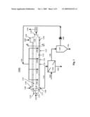
[0008]FIG. 1 is a block diagram of an exemplary embodiment of a system 1000;
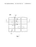
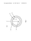
[0009]FIG. 2 is a cross section A-A taken from FIG. 1;
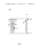
[0010]FIG. 3 is a block diagram of an exemplary embodiment of a system 3000;
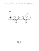
[0011]FIG. 4 is a cross section B-B taken from FIG. 3;
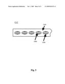
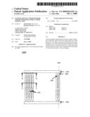
[0012]FIG. 5 is a cross section C-C taken from FIG. 3;
[0013]FIG. 6 is a block diagram of an exemplary embodiment of a system 6000;
[0014]FIG. 7 is a block diagram of an exemplary embodiment of a system 7000;
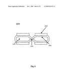
[0015]FIG. 8 is a cross section D-D taken from FIG. 7; and
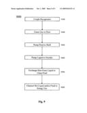
[0016]FIG. 9 is a flowchart of an exemplary embodiment of a method 9000.
DETAILED DESCRIPTION
[0017]Certain exemplary embodiments provide an energy and particle recuperator (EPR) for dirty gas fluids and/or gas solids fluid mixes. Gas fluids and/or gas solids fluid mixes stream through a vessel. Heat contained in the gas fluids and/or gas solid fluid mixes is partially transferred to a liquid spray fluid sprayed inside the vessel. Heat is transferred from the liquid to a clean process fluid via a heat exchanger.
[0018]Many industrial facilities generate hot gas fluids (for example exhaust gas from burners, exhaust air with odor particles, and/or steam from dryers, etc.), which can escape hot and unpurified from an exhaust chimney into the environment. The hot gas fluids can comprise heat energy as well as particulate matter.
[0019]Certain exemplary embodiments provide an EPR adapted to transfer a portion of heat energy contained in hot gases to a relatively clean fluid. Certain exemplary embodiments spray the hot gas fluids and/or gas solid fluids mixes with a liquid. The liquid spray can remove particulates of a certain minimum size from the gas fluids and/or gas solid fluids mixes. Removal of particulates can result in an exit gas that is significantly cleaner.
[0020]Extracted heat that has been transferred to the liquid can be used in many different ways, such as by integration into different processes, thereby saving energy that might otherwise be used.
[0021]Certain exemplary embodiments provide for systems, devices, and/or methods adapted to recover heat energy and/or separate suspended solids, particles, odors, etc. from gas fluids and/or gas-solids-liquid mixes (for example exhaust air from manufacturing processes). Certain exemplary embodiments provide an EPR adapted for use with gas fluids and gas-solids-liquid mixes.
[0022]Certain exemplary embodiments facilitate heat exchange from a contaminated fluid to a relatively pure fluid. Certain exemplary embodiments utilize heat exchangers that channel fluids through relatively wide conduits in order to avoid deposits caused for example by contaminated fluid (e.g., foreign particles and/or dust, etc.).
[0023]FIG. 1 is a block diagram of an exemplary embodiment of a system 1000, which can comprise a nearly horizontal vessel 1100. Vessel 1100 can comprise: [0024]an inner shell 1110, which can be in contact with a liquid, fluid, and/or gas channeled through vessel 1100; [0025]an outer shell 1120, which with can define a heat exchange fluid channel 1190; [0026]a set of spacers 1130, which can assist in maintaining a size and/or dimensions of fluid channel 1190 along a length of vessel 1100; [0027]a gas inlet 1140 adapted to receive a flow of hot gas fluids and/or gas solids fluid mixes 1500; [0028]a gas outlet 1150 adapted to vent flow of cooled gas fluids and/or gas solids fluid mixes 1550 to one or more devices and/or systems that cause cooled gas fluids and/or gas solids fluid mixes 1550 to be vented to an environment; [0029]a fan 1050 adapted to cause the gas fluid to be conveyed through vessel 1100; [0030]a heat transfer fluid inlet 1160 adapted to receive a relatively cold heat transfer fluid flow 1600; cold heat transfer fluid flow 1600 is adapted to receive a flow of heat from flow of hot gas fluids and/or gas solids fluid mixes 1500; [0031]a heat transfer fluid outlet 1170 adapted to transfer a heated heat transfer fluid flow 1650 to a user of heat; the user of heat is adapted to beneficially use heat energy recovered from flow of hot gas fluids and/or gas solids fluid mixes 1500 via heated heat transfer fluid 1650; and/or [0032]a drain 1180 adapted to channel flow of a heat transfer liquid sprayed in vessel 1100 to a liquid/liquid heat exchanger 1200.
[0033]Vessel 1100 can cause hot gas fluids and/or gas solids fluid mixes 1500 to flow in a substantially horizontal path through vessel 1100. Cold heat transfer fluid flow 1600 can flow through fluid channel 1190 and, via conduction and/or convection, receive heat from hot gas fluids and/or gas solids fluid mixes 1500. In certain exemplary embodiments, cold heat transfer fluid flow 1600 is counter-current to hot gas fluids and/or gas solids fluid mixes 1500 to improve heat exchange.
[0034]Because cold heat transfer fluid flow 1600 does not directly contact hot gas fluids and/or gas solids fluid mixes 1500, heated heat transfer fluid 1650 will not be contaminated by substances present in hot gas fluids and/or gas solids fluid mixes 1500.
[0035]Vessel 1100 and/or other components of system 1000 can be referred to as an EPR. Vessel 1100 can comprise a substantially hollow body 1105, which can have a substantially cylindrical portion 1125. Substantially cylindrical portion 1125 can define a central longitudinal axis 1115. Central longitudinal axis 1115 can be substantially perpendicular to a primary direction of flow 1135 of the gas fluid through gas inlet 1140. In certain exemplary embodiments, central longitudinal axis 1115 can be substantially horizontal relative to the surface of the earth.
[0036]A set of nozzles; such as spray nozzle 1900, spray nozzle 1920, spray nozzle 1940, and spray nozzle 1960; can be adapted to spray a liquid into vessel 1100.
[0037]Liquid sprayed via the set of nozzles can be adapted to collect particulates entrained in the gas fluid. The liquid sprayed via the set of nozzles can be adapted to receive heat energy from the gas fluid. The energy and particle recuperator can define heat exchange fluid channel 1190 with serrated surfaces. Heat exchange fluid channel 1190 can substantially surround at least a portion of substantially cylindrical portion 1125 of vessel 1100. Heat exchange fluid channel 1190 can be adapted to receive a heat transfer fluid. Vessel 1100 can be adapted to cause heat energy to be transferred from the gas fluid to the heat transfer fluid without the heat transfer fluid directly contacting the gas fluid.
[0038]A liquid sprayed through the set of spray nozzles can extract particles of certain sizes from hot gas fluids and/or gas solids fluid mixes 1500. Those skilled in the art will recognize that system 1000 will generally not be able to recover a high percentage, for example, of submicron sized particulates, but will be at least partially effective in removing particulates having a diameter of greater than 100 microns.
[0039]An apparatus, which promotes the heat exchange between two fluids without mixing the fluids through the use of two separate conduits (e.g. channels, plates), can be referred to as a heat exchanger (HE). The heat exchange in this process can take place via a suitable heat conductor (for example metal).
[0040]Certain exemplary embodiments can recover heat energy and/or entrained substances from hot gas fluids and/or gas solids fluid mixes 1500 (e.g. hot exhaust air), which can be an energy source for an energy recovery system. Vessel 1100 can be a pipe or another hollow body of a substantially circular cross-section. The formation of relatively fine drops by the set of spray nozzles causes hot gas fluids and/or gas solids fluid mixes 1500 to cool and cold liquid spray fluid flow 1700 to be heated. After being so heated, hot liquid spray fluid flow 1750 can collect on the bottom of vessel 1100 and flow to drain 1180. Therefore, cooled gas fluids and/or gas solids fluid mixes 1550 will exit vessel 1100 via gas outlet 1150 after being cooled down and having certain impurities (e.g., particulates) removed.
[0041]Hot liquid spray fluid flow 1750 can flow to heat exchanger 1200, into which a cool clean liquid fluid flow 1800 also enters. Cool clean liquid fluid flow 1800 receives heat energy from hot liquid spray fluid flow 1750. Due to its purity, after receiving the heat energy, heated clean liquid fluid flow 1850 can be used in a heat consuming process. Heat exchanger 1200 can be adapted to receive the liquid sprayed via the set of nozzles. Heat exchanger 1200 adapted to transfer heat energy from the liquid sprayed via the set of nozzles to a clean process fluid, such as cool clean liquid fluid flow 1800.
[0042]In certain exemplary embodiments, a cooled liquid spray fluid flow 1780 can be routed to a particle separator 1300, which is adapted to remove particles removed from hot gas fluids and/or gas solids fluid mixes 1500 and entrained in cooled liquid spray fluid flow 1780. In certain exemplary embodiments the particulates can settle via gravity and/or removed via a cyclonic action in particle separator 1300. Particulates removed in particle separator 1300 report to a particulate flow 1790, which can be disposed of in accordance with governmental regulations.
[0043]Cold liquid spray fluid flow 1700 can be routed from particle separator 1300 to a pump 1400, which provides motive energy to channel liquid spray fluid flow 1700 to the set of nozzles of system 1000. Pump 1400 can be adapted to cause a conveyance of the liquid sprayed via the set of nozzles to the set of nozzles.
[0044]In certain exemplary embodiments, liquid/liquid heat exchanger 1200 can comprise a set of pipes, which can each define a longitudinal axis. Each of the set of longitudinal axes can be substantially parallel. Each of the set of pipes is adapted to receive a flow of a heat transfer fluid. Each of the set of pipes can comprise a substantially planar surface over at least a portion of a pipe length so as to form a flow channel with an elongated profile. Each pipe can have substantially round ends, which are hydraulically coupled to collecting pipes. In certain exemplary embodiments, each of the set of pipes can have a set of fins attached each flat surface in order to increase a surface area for conductive and/or convective heat transfer between fluids. In certain exemplary embodiments, each of the set of pipes can have a dimpled and/or irregular surface in order to improve heat transfer kinetics.
[0045]Liquid/liquid heat exchanger 1200 can transfer heat between hot liquid spray fluid flow 1750 and cool clean liquid fluid flow 1800 without mixing the two fluids.
[0046]Liquid/liquid heat exchanger 1200 can comprise flow channels that exhibit a relatively large surface and can define a profile in a way that a relatively thin film of the heat transfer fluid flows through the flow channels.
[0047]In certain exemplary embodiments, liquid/liquid heat exchanger 1200 can comprise pipes that have a substantially flat surface over at least a portion of each pipe. In such embodiments, the pipe ends can be rounded and set into openings defined by collecting pipes. Certain exemplary embodiments can utilize corrugated ribs between flat pipe portions.
[0048]In certain exemplary embodiments, a flat side of a portion of a first pipe of the set of pipes can at least partially touch a flat side of a portion of a second pipe of the set of pipes. At such connection points, a flow of hot liquid spray fluid flow 1750 can be interrupted, resulting in a relative improvement of the heat transfer. In certain exemplary embodiments, liquid/liquid heat exchanger 1200 can define a plurality of flow channels that run substantially parallel to each other.
[0049]In certain exemplary embodiments, liquid/liquid heat exchanger 1200 can define a serpentine flow channel, thus increasing a relative path length of the heat transfer fluid resulting in a relative increase in heat transfer. A stability of liquid/liquid heat exchanger 1200 can be increased in relative terms by welding or gluing long sides in connecting areas to increase stability.
[0050]Certain exemplary embodiments can be adapted for: [0051]heat energy recovery from gas solid fluids and gas-solids-liquid mixes; and/or [0052]purification of gas solids fluids and gas-solids-liquid mixes.
[0053]FIG. 2 is a cross section A-A taken from FIG. 1, which illustrates spray nozzle 1180. System 1000 can comprise a set of braces 2100. In certain exemplary embodiments, set of braces 2100 can be serrated in order to improve heat transfer kinetics.
[0054]As illustrated in FIG. 2, a cross section of vessel 1100 can define two concentric cylinders. Outer shell 1120 can be attached to inner shell 1110 as if outer shell 1120 were a mantle around inner shell 1110 (e.g., as a double shell pipe). Cold heat transfer fluid flow 1600 can be channeled through fluid channel 1190, flowing as a mantle stream around inner shell 1110, and exiting via heat transfer fluid outlet 1170 of FIG. 1. Set of braces 2100 between inner shell 1110 and outer shell 1120 can maintain fluid channel 1190 and/or increase heat exchange kinetics due to an increase surface in surface area available for heat exchange.
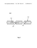
[0055]FIG. 3 is a block diagram of an exemplary embodiment of a system 3000, which can be used in certain exemplary embodiments as a liquid/liquid heat exchanger in applications such as liquid/liquid heat exchanger 1200 of FIG. 1. System 3000 can comprise a first collecting pipe 3100 and a second collecting pipe 3200, each of which can be adapted to convey a heat exchange fluid in and/or out of system 3000. Each of first collecting pipe 3100 and a second collecting pipe 3200 are hydraulically coupled to a set of pipes 3300. First collecting pipe 3100 and/or second collecting pipe 3200 can have any cross-sectional profile. The cross-sectional profile, for example, can round (e.g., circular or oval), rectangular, triangular, and/or square, etc. First collecting pipe 3100 and/or second collecting pipe 3200 can be made from a metal, such as iron, steel, copper, lead, and/or aluminum, etc. In certain exemplary embodiments, first collecting pipe 3100 and/or second collecting pipe 3200 can be made of plastic. In such embodiments, long sides of the plastic pipes can be glued together in connecting areas by plasticizing of a synthetic material.
[0056]System 3000 can comprise a set of pipes 3300. Each of set of pipes 3300 can define a longitudinal axis, such as longitudinal axis 3500. Each of the set of longitudinal axes can be substantially parallel. A heat transfer fluid is channeled through one of first collecting pipe 3100 and second collecting pipe 3200 to set of pipes 3300, where this heat transfer fluid is warmed and then flows to the other collecting pipe. The heat transfer fluid can be any suitable liquid such as water; glycol; brine; potassium formate; a parafinnic fluid; a silicone based fluid; a hydrocarbon based fluid; and/or a proprietary fluid such as Duratherm®, Permatherm®, and/or Dowtherm®; etc.
[0057]In certain exemplary embodiments, system 3000 can utilize cooling fins 3400 on one or more of set of pipes 3300 to increase relative heat transfer surface areas and improve heat transfer kinetics. In certain exemplary embodiments, a longitudinal axis of each of cooling fins 3400 can be approximately perpendicular to a longitudinal axis of each of set of pipes 3300. In certain exemplary embodiments, the longitudinal axis of each of cooling fins 3400 can be substantially non-perpendicular to the longitudinal axis of each of set of pipes 3300.
[0058]FIG. 4 is a cross section B-B taken from FIG. 3, which illustrates an exemplary cross-section of set of pipes 3300 at a location of hydraulic coupling to first collecting pipe 3100. The ends of set of pipes 3300 can have a substantially circular profile, which can be inserted into created holes (e.g., drilled holes) in first collecting pipe 3100 and/or second collecting pipe 3200 that correspond to an exterior diameter of ends of set of pipes 3300. Pipe ends can be inserted into the created holes, anchored, and sealed, for example, via welding and/or gluing.
[0059]FIG. 5 is a cross section C-C taken from FIG. 3, which illustrates an exemplary cross section of set of pipes 3300. In certain exemplary embodiments, set of pipes 3300 can comprise a substantially planar surface 3400. In certain exemplary embodiments, substantially planar surface 3400 can be pressed flat for example by rolling. Flattening can be done in such a way that portions of long sides have a relatively small distance to each other and/or partially connect with each other. Certain exemplary embodiments can be dimpled via compression and/or spot welding technology in order to result in a flow of heat exchange fluid that follows a predetermined curved path through one or more of set of pipes 3300. Each of set of pipes 3300 can comprise a substantially planar surface 3400 over at least a portion of a pipe length so as to partially define a channel, such as channel 7600 of FIG. 7, between each pair of adjacent pipes of set of pipes 3300. A cross-section of each pipe at the portion of the pipe length comprising a pair of substantially parallel opposing planar sides can have at least one rounded edge. Each of set of pipes 3300 can comprise ends 3600, which can have a substantially circular cross-section. Each of set of pipes 3300 can comprise fins.
[0060]FIG. 6 is a block diagram of an exemplary embodiment of a system 6000, which can comprise a flattened portion 6200 of a pipe of an exemplary liquid/liquid heat exchanger. In certain exemplary embodiments, flattened portion 6200 can be mechanically and/or thermally coupled to a cooling fin 6400. In certain exemplary embodiments, long sides can connect to each other along a substantially straight line that is substantially parallel to a longitudinal axis of the pipe. In certain exemplary embodiments, a pair of partial channels 6100 can be defined by system 6000. Each of pair of partial channels 6100 can be adapted to channel a flow of transfer fluid. Each of pair of partial channels 6100 can be hydraulically separated by a crimped portion 6300.
[0061]FIG. 7 is a block diagram of an exemplary embodiment of a system 7000, which illustrates a detail of a set of pipes 7100 that are substantially adjacent with substantially parallel longitudinal axes. Set of pipes 7100 can define a set of channels such as channel 7600. In certain exemplary embodiments, channel 7600 can be a serpentine channel that defines a tortuous path for liquids flowing through channel 7600. Channel 7600 can be interrupted by connection areas, such as connection area 7200, between pairs of adjacent pipes. Each connection area, such as connection area 7200, can define a substantially rhombic shape. A cross-section of each pipe at the portion of the pipe length that comprises a pair of substantially parallel opposing planar sides can have at least one rounded edge.
[0062]FIG. 8 is a cross section D-D taken from FIG. 7. Each of set of pipes 7100 can comprise a connecting area 7200 of a long side 7500 that extends in pre-established interspaces across a longitudinal direction of set of pipes 7100, such as over approximately half of a length of long side 7500. Connection area 7200 is marked with a dotted line in FIG. 7. In certain exemplary embodiments, connecting area 7200 of adjacent pipes is located across from each other. Certain exemplary embodiments can utilize a rhombic stamp to create connecting area 7200 on adjacent pipes. An s-shaped flow 7300 of the heat transfer fluid can be achieved via connecting areas such as connecting area 7200. In certain exemplary embodiments, connecting area 7200 can be mechanically coupled to a corresponding connecting area of an adjacent pipe such as by welding. Certain exemplary embodiments can utilize a set of fins 7400 for relative improvement of heat transfer kinetics.
[0063]FIG. 9 is a flowchart of an exemplary embodiment of a method 9000. At activity 9100, an EPR is operatively coupled to a source of hot gas. The EPR can be coupled via a set of releasably attachable fasteners at a flange. In certain exemplary embodiments, an inlet duct can be welded to the EPR in order to avoid gas leaks.
[0064]At activity 9200, a flow of hot gas is caused to flow through the EPR. Certain exemplary embodiments can cause a gas fluid to be channeled through the EPR, which can be a substantially horizontal vessel. The EPR can define an inner shell and an outer shell. A heat exchange fluid channel can be defined by the inner shell and the outer shell. The heat exchange fluid channel can comprise serrated heat transfer surfaces. The heat exchange fluid channel can be adapted to receive a heat transfer fluid flow. The flow of hot gas can be caused by a blower and/or fan. After passage through the EPR, the cooled gas can be vented to an environment such as the atmosphere.
[0065]At activity 9300, in certain exemplary embodiments, a heat transfer fluid is pumped to the channel defined by an inner shell and an outer shell of the EPR. In embodiments comprising the channel, the hot gas transfers heat to the heat transfer fluid via conduction and/or convection. The heat transfer fluid flow can be adapted to remove heat energy from the gas fluid. The heat transfer fluid flow can be adapted to convey the heat energy to an energy user.
[0066]At activity 9400, a liquid is pumped to a set of spray nozzles of the EPR. The set of nozzles can be adapted to spray a liquid into the EPR. Liquid sprayed via the set of nozzles can be adapted to collect particulates entrained in the gas fluid. The liquid sprayed via the set of nozzles receives heat energy from the gas fluid. The liquid can be recirculated and can be contaminated with certain impurities present in the hot gas. The liquid directly contacts the hot gas and thereby absorbs heat from the hot gas. The liquid can be collected at a drain of the EPR and can be pumped to a heat exchanger. In certain exemplary embodiments, the particulates can be removed from the sprayed liquid via a particle separator.
[0067]At activity 9500, heat transferred to the sprayed liquid from the hot gas is transferred to a clean process fluid via the heat exchanger. The heat exchanger can be a liquid-liquid heat exchanger that utilizes a clean fluid adapted to absorb heat energy from the liquid. The liquid can then be recirculated to the sprays of the EPR via a pump.
[0068]At activity 9600, the heat transfer fluid and/or the clean fluid are routed to an energy use that beneficially uses the heat energy transferred from the hot gas.
[0069]Heat transferred from the hot gas to the heat transfer fluid and/or the clean fluid can be utilized by an energy consumer such as a hot water user and/or a building heating system, etc.
Definitions
[0070]When the following terms are used substantively herein, the accompanying definitions apply. These terms and definitions are presented without prejudice, and, consistent with the application, the right to redefine these terms during the prosecution of this application or any application claiming priority hereto is reserved. For the purpose of interpreting a claim of any patent that claims priority hereto, each definition (or redefined term if an original definition was amended during the prosecution of that patent), functions as a clear and unambiguous disavowal of the subject matter outside of that definition. [0071]a--at least one. [0072]activity--an action, act, step, and/or process or portion thereof. [0073]adapted to--made suitable or fit for a specific use or situation. [0074]and/or--either in conjunction with or in alternative to. [0075]apparatus--an appliance or device for a particular purpose [0076]can--is capable of, in at least some embodiments. [0077]channel--(v) to cause to flow via a defined passage, conduit, and/or groove adapted to convey one or more fluids. (n) a passage, conduit, and/or groove adapted to convey one or more fluids. [0078]comprise--to include but be not limited to. [0079]connect--to join or fasten together. [0080]cool--to make less warm, to remove heat from, and/or to reduce the molecular and/or kinetic energy of. [0081]couple--to linking in some fashion. [0082]define--to establish the outline, form, or structure of. [0083]device--a machine, manufacture, and/or collection thereof. [0084]install--to connect or set in position and prepare for use. [0085]may--is allowed and/or permitted to, in at least some embodiments. [0086]method--a process, procedure, and/or collection of related activities for accomplishing something. [0087]particle separator--a device and/or system adapted to separate particles from a liquid stream such as by gravity settling and/or a cyclonic action. [0088]plurality--the state of being plural and/or more than one. [0089]predetermined--established in advance. [0090]provide--to furnish, supply, give, and/or make available. [0091]receive--to get as a signal, take, acquire, and/or obtain. [0092]recuperator--a system adapted to recover energy from a gas stream. [0093]repeatedly--again and again; repetitively. [0094]request--to express a desire for and/or ask for. [0095]set--a related plurality. [0096]substantially--to a great extent or degree. [0097]support--to bear the weight of, especially from below. [0098]system--a collection of mechanisms, devices, machines, articles of manufacture, processes, data, and/or instructions, the collection designed to perform one or more specific functions. [0099]temperature--measure of the average kinetic energy of the molecules in a sample of matter, expressed in terms of units or degrees designated on a standard scale. [0100]via--by way of and/or utilizing.
Note
[0101]Still other substantially and specifically practical and useful embodiments will become readily apparent to those skilled in this art from reading the above-recited and/or herein-included detailed description and/or drawings of certain exemplary embodiments. It should be understood that numerous variations, modifications, and additional embodiments are possible, and accordingly, all such variations, modifications, and embodiments are to be regarded as being within the scope of this application.
[0102]Thus, regardless of the content of any portion (e.g., title, field, background, summary, description, abstract, drawing figure, etc.) of this application, unless clearly specified to the contrary, such as via explicit definition, assertion, or argument, with respect to any claim, whether of this application and/or any claim of any application claiming priority hereto, and whether originally presented or otherwise: [0103]there is no requirement for the inclusion of any particular described or illustrated characteristic, function, activity, or element, any particular sequence of activities, or any particular interrelationship of elements; [0104]any elements can be integrated, segregated, and/or duplicated; [0105]any activity can be repeated, any activity can be performed by multiple entities, and/or any activity can be performed in multiple jurisdictions; and [0106]any activity or element can be specifically excluded, the sequence of activities can vary, and/or the interrelationship of elements can vary.
[0107]Moreover, when any number or range is described herein, unless clearly stated otherwise, that number or range is approximate. When any range is described herein, unless clearly stated otherwise, that range includes all values therein and all subranges therein. For example, if a range of 1 to 10 is described, that range includes all values therebetween, such as for example, 1.1, 2.5, 3.335, 5, 6.179, 8.9999, etc., and includes all subranges therebetween, such as for example, 1 to 3.65, 2.8 to 8.14, 1.93 to 9, etc.
[0108]When any claim element is followed by a drawing element number, that drawing element number is exemplary and non-limiting on claim scope.
[0109]Any information in any material (e.g., a United States patent, United States patent application, book, article, etc.) that has been incorporated by reference herein, is only incorporated by reference to the extent that no conflict exists between such information and the other statements and drawings set forth herein. In the event of such conflict, including a conflict that would render invalid any claim herein or seeking priority hereto, then any such conflicting information in such material is specifically not incorporated by reference herein.
[0110]Accordingly, every portion (e.g., title, field, background, summary, description, abstract, drawing figure, etc.) of this application, other than the claims themselves, is to be regarded as illustrative in nature, and not as restrictive.
User Contributions:
comments("1"); ?> comment_form("1"); ?>Inventors list |
Agents list |
Assignees list |
List by place |
Classification tree browser |
Top 100 Inventors |
Top 100 Agents |
Top 100 Assignees |
Usenet FAQ Index |
Documents |
Other FAQs |
User Contributions:
Comment about this patent or add new information about this topic:
Images included with this patent application:
 |  |
 |  |
 |  |
 |  |
 |  |
| Similar patent applications: | |
| Date | Title |
|---|---|
| 2011-10-20 | Systems and methods for enhancing energy storage in quantum thermodynamic systems |
| 2011-11-24 | System and methods for pre-heating fuel in a power plant |
| 2011-05-26 | Processes and devices for regenerating gasoline particulate filters |
| 2011-12-08 | Systems and methods for energy storage and recovery using gas expansion and compression |
| 2011-10-27 | System and methods for optimizing efficiency of a hydraulically actuated system |
| New patent applications in this class: | |
| Date | Title |
|---|---|
| 2016-12-29 | Cantilevered flow distributing apparatus |
| 2016-04-28 | Exhaust gas treatment device, especially for an exhaust gas flow path of an internal combustion engine, and method for manufacturing an exhaust gas treatment device |
| 2016-03-03 | Exhaust gas purification system |
| 2016-02-25 | Inclined perforated plate at radial inlet |
| 2015-05-28 | System and method of controlling exhaust temperature |
| Top Inventors for class "Power plants" | |
| Rank | Inventor's name |
|---|---|
| 1 | Gabriel L. Suciu |
| 2 | Patrick Benedict Melton |
| 3 | Eugene V. Gonze |
| 4 | Thomas Edward Johnson |
| 5 | Jan Hodgson |