Patent application title: PIECE OF JEWELLERY
Inventors:
Dirk Stichnoth (Hannover, DE)
Jorg Stichnoth (Hannover, DE)
IPC8 Class: AA44C1702FI
USPC Class:
63 291
Class name: Jewelry gem setting detachable
Publication date: 2009-09-24
Patent application number: 20090235690
Inventors list |
Agents list |
Assignees list |
List by place |
Classification tree browser |
Top 100 Inventors |
Top 100 Agents |
Top 100 Assignees |
Usenet FAQ Index |
Documents |
Other FAQs |
Patent application title: PIECE OF JEWELLERY
Inventors:
Dirk Stichnoth
Jorg Stichnoth
Agents:
WHITHAM, CURTIS & CHRISTOFFERSON & COOK, P.C.
Assignees:
Origin: RESTON, VA US
IPC8 Class: AA44C1702FI
USPC Class:
63 291
Abstract:
In the case of a piece of jewelry with a jewelry body (1) and at least one
jewelry insert (4) which has a channel opening (10) into which is
inserted a fastening pin (7) which, for the purpose of fastening the
jewelry insert (4) in the jewelry body (1), protrudes out of the jewelry
insert (4) at least one end and into a first recess (8) of the jewelry
body (1), a secure and easily maneuverable fastening of the jewelry
insert to the jewelry body can be realised in that the first recess (8)
is a threaded passage hole through which the fastening pin (7), which is
designed as a rigid threaded pin, can be screwed and, by means of a
section (9) which protrudes through the threaded passage hole (8),
protrudes into the channel opening (10).Claims:
1. Piece of jewelry with a jewelry body (1) and at least one jewelry
insert (4) which has a channel opening (10) into which is inserted a
fastening pin (7) which, for the purpose of fastening the jewelry insert
(4) in the jewelry body (1), protrudes out of the jewelry insert (4) at
least one end and into a first recess (8) of the jewelry body (1),
characterized in that the first recess (8) is a threaded passage hole
through which the fastening pin (7), which is designed as a rigid
threaded pin, can be screwed and, by means of a section (9) which
protrudes through the threaded passage hole (8), protrudes into the
channel opening (10).
2. Piece of jewelry according to claim 1, characterized in that the channel opening (10) of the jewelry insert (4) is a passage opening, and in that the fastening pin (7) protrudes into a second recess (11) of the jewelry body (1) by means of an end (15) which protrudes through the jewelry insert (4).
3. Piece of jewelry according to claim 2, characterized in that the second recess (11) is of smooth-walled design.
4. Piece of jewelry according to claim 2, characterized in that the end (15) which protrudes through the jewelry insert (4) is designed with a reduced diameter, and in that the second recess (11) has a correspondingly reduced diameter in relation to the passage channel opening (10) of the jewelry insert (4).
5. Piece of jewelry according to claim 4, characterized in that the shoulder (17) formed by the reduction in diameter forms a screw-in stop for the fastening pin (7).
6. Piece of jewelry according to claim 1, characterized in that the threaded pin (7) is provided with its thread (14) over at least half of its length.
7. Piece of jewelry according to claim 1, characterized in that the fastening pin (7) is provided on one end side with an actuating device (8).
8. Piece of jewelry according to claim 7, characterized in that the actuating device is an engagement slot (8) for a screw driver.
9. Piece of jewelry according claim 1,_characterized in that the fastening pin (7) can be fully screwed at the end provided with the actuating device into the first recess (8).
10. Piece of jewelry according to claim 1, characterized in that the jewelry insert (4) is of cylindrical design with a cylinder axis (6) and can be inserted into a corresponding, concentric, cylindrical receiving opening (2) of the jewelry body (1), and in that the channel opening (10) is oriented perpendicularly to the cylinder axis (6).
11. Piece of jewelry according to claim 10, characterized in that the cylindrical jewelry insert (4) and the cylindrical opening (2) are designed in such a manner that the jewelry insert (4) is mounted in a rotationally fixed manner in the opening (2).
12. Piece of jewelry according to claim 1, characterized in that the jewelry body (1) has at least one flange-like angled portion (16) in which the threaded passage hole (8) is located.
13. Piece of jewelry according to claim 12, characterized in that a further flange-like angled portion (16) which is parallel to the angled portion and has the second recess (11) is provided.
Description:
[0001]The invention relates to a piece of jewelry with a jewelry body and
at least one jewelry insert which has a channel opening into which is
inserted a fastening pin which, for the purpose of fastening the jewelry
insert in the jewelry body, protrudes out of the jewelry insert at least
one end and into a first recess of the jewelry body.
[0002]Pieces of jewelry are generally designed with a jewelry body which generally determines the shape and possibility of use of the piece of jewelry as ring, pendant, brooch, chain or the like. The jewelry body is frequently provided with a jewelry insert which can be formed by a precious stone, semi-precious stone, a piece of precious metal or the like. The jewelry insert may be composed of the jewelry element itself, however the jewelry element is frequently mounted in a setting which forms the jewelry insert.
[0003]Whereas, in conventional technology, the jewelry insert is connected fixedly to the jewelry body, for example by means of adhesive bonding, jewelry inserts have for some time frequently been connected releasably to the jewelry body. For example, it is known by means of U.S. Pat. No. 3,959,989 to fasten a planar jewelry element for a finger ring to the ring body by means of a spring pin which protrudes through a passage channel of the jewelry element and can snap into blind bores of the ring body.
[0004]A similar technique is known by means of DE 70 26 255 U1 for the design of a wrist watch strap formed from metal links. In this case, the recesses which serve to receive the resilient ends of the resilient fastening pin can be designed as passage holes, and therefore the resilient end of the fastening pin can be pressed in with the aid of an elongate tool, for example in the form of a pin, which is inserted through a passage hole such that the connection produced by the fastening pin can be released with the aid of the tool.
[0005]However, the handling of a resilient fastening pin requires a fair amount of skill and is an obstacle to the purpose of the releasable fastening of the jewelry insert to the jewelry body, namely for being able to use different jewelry inserts for the same jewelry body, because the non-expert owner of the piece of jewelry may have problems with interchanging the jewelry insert.
[0006]The invention is therefore based on the object of designing a piece of jewelry of the type mentioned at the beginning in such a manner that a releasable, but nevertheless secure fastening of the jewelry insert to the jewelry body is possible, which fastening, furthermore, is simple to bring about.
[0007]To achieve this object, according to the invention a piece of jewelry of the type mentioned at the beginning is characterized in that the first recess is a threaded passage hole through which the fastening pin, which is designed as a rigid threaded pin, can be screwed and, by means of a section which protrudes through the threaded passage hole, protrudes into the channel opening.
[0008]In the case of the piece of jewelry according to the invention, the fastening by means of resilient elements is therefore dispensed with. On the contrary, it takes place by means of a rigid fastening pin which is provided with an external thread and is screwed by means of said external thread through a threaded passage hole of the jewelry body before it protrudes into the channel opening. That section of the threaded pin which protrudes into the channel opening brings about the fastening, for example in interaction with a receiving opening in the jewelry body for the jewelry insert.
[0009]A stable fastening by means of the threaded pin on its own is achieved if the channel opening of the jewelry insert is a passage opening, and the fastening pin protrudes into a second recess of the jewelry body by means of an end which protrudes through the jewelry insert. In this case, it is of importance, for the fastening security, that the threaded pin is already screwed down on the side on which it is inserted into the jewelry body. If the threaded pin is provided with a thread, for example over at least half of its length, a multiplicity of revolutions of the threaded pin is required in order to loosen the latter to an extent such that it again releases the jewelry insert. It is virtually impossible in this case to inadvertently lose the jewelry insert from the jewelry body.
[0010]In the embodiment with the second recess, it is not necessary for the latter also be designed as a threaded hole. On the contrary, it is preferred for the second recess to be of smooth-walled design. This embodiment can be used in order to bring about a screw-in limitation of the threaded pin by that end of the threaded pin which protrudes through the jewelry insert being designed with a reduced diameter, and the second recess having a correspondingly reduced diameter in relation to the passage channel opening of the jewelry insert. In this case, the shoulder formed by the reduction in diameter can form a screw-in stop for the fastening pin.
[0011]The fastening pin is preferably provided on one side with an actuating device, preferably in the form of an engagement slot for a screwdriver. As a result, the threaded pin can be fully screwed in the manner of a headless screw into the first recess, thus enabling the threaded pin to be arranged in the piece of jewelry inconspicuously such that it does not interfere with the design of the piece of jewelry.
[0012]In a preferred embodiment of the invention, the jewelry insert can be of cylindrical design with a cylinder axis and can be insertable into a corresponding, concentric, cylindrical opening of the jewelry body, with the channel opening being oriented perpendicularly to the cylinder axis. For precise orientation of the channel opening in such a manner that the channel opening is in alignment with the at least one recess, preferably with both of the recesses of the jewelry body, it is expedient if the cylindrical jewelry insert and the cylindrical opening are designed in such a manner that the jewelry insert is mounted in a rotationally fixed manner in the opening, thus resulting in an automatic, correct adjustment of the jewelry insert relative to at least the first recess or to both of the recesses. This is possible, for example, by means of the use of a noncircular cross section for the jewelry insert and recess or by means of studs or lugs which are provided on the jewelry insert and can be pushed into an associated groove in the receptacle.
[0013]In an alternative embodiment of the invention, the jewelry body can have at least one flange-like angled portion in which the threaded passage hole is located. For a design with a second recess, a further flange-like angled portion which is parallel to the angled portion and has the second recess can be provided. In this embodiment, the threaded pin runs perpendicularly to the ring access.
[0014]The shape of the jewelry insert can have numerous variants, in particular if two flange-like angled portions are provided. In addition to cylindrical shapes with circular and polygonal cross sections, use may also be made of spherical, oval and similar jewelry inserts.
[0015]The invention is to be explained in more detail below with reference to exemplary embodiments which are illustrated in the drawing, in which:
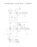
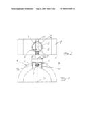
[0016]FIG. 1 shows an enlarged and schematic illustration of a ring with a jewelry insert in the form of a setting for a jewelry stone, in a side view;
[0017]FIG. 2 shows the ring according to FIG. 1, in a plan view;
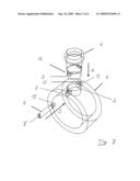
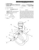
[0018]FIG. 3 shows a perspective, exploded illustration of the ring according to FIG. 1;
[0019]FIG. 4 shows a view of a threaded pin;
[0020]FIG. 5 shows a section through the height of the ring in the region of the recesses for the fastening pin;
[0021]FIG. 6 shows an embodiment of a piece of jewelry with two mutually opposite angled portions having a first recess and a second recess for receiving a fastening pin;
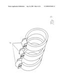
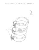
[0022]FIG. 7 shows a perspective illustration of various shapes of jewelry inserts for a ring designed according to FIG. 5;
[0023]FIG. 8 shows an illustration of differently sized jewelry inserts for a ring according to FIG. 5;
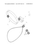
[0024]FIG. 9 shows an illustration of different jewelry bodies for realizing the invention on a ring, on a bracelet, on a pendant fastened on a chain, and as earrings.
[0025]FIG. 1 shows a piece of jewelry with a jewelry body 1 in the form of a ring, in a side view. The ring 1 is provided at one point with a radial, cylindrical receiving opening 2 which extends over the thickness of the material of the ring 1. A cylindrical extension 3 of a jewelry insert 4 in the form of a setting for a jewelry stone (not illustrated) is inserted into the cylindrical receiving opening 2. The ring 1, which is designed here in the shape of a circular ring, has a ring axis 5 to which a central axis 6 of the cylindrical extension 3 or of the jewelry insert 4 runs perpendicularly. A fastening pin 7 in the form of a threaded pin is inserted through the ring 1 in the cylindrical extension 3 parallel to the ring axis. On its end side, the threaded pin 7 is provided with a slot 7' which permits, in a customary manner, the engagement of a matching screwdriver such that the threaded pin 7 can be rotated by means of a screwdriver.
[0026]The plan view of FIG. 2 shows the cylindrical receiving opening 2 in which the axis 6 of the cylindrical extension 3 of the setting 4 runs centrally. Perpendicularly thereto, there is a first recess 8 in the material of the ring 1, which recess is provided with an internal thread and through which the fastening pin 7, which is provided with the external thread, is screwed such that it protrudes by means of a section 9 into a channel opening 10 of the cylindrical extension 3.
[0027]In the exemplary embodiment illustrated, the channel opening 10 is a passage channel opening which, on the side lying opposite the first recess 8, is in alignment with a second recess 11 which is likewise designed as passage opening, but is of smooth-walled design, i.e. does not have an internal thread. The fastening pin 7 protrudes into the second recess 11 at its free end.
[0028]Since the receiving opening 2 of the ring 1 and the cylindrical extension 3 of the setting 4 both have circular-cylindrical cross sections, the setting 4 could be inserted into the receiving opening 2 in any random rotational position which would not ensure that the channel opening 10 would be aligned with the first recess 8 and the second recess 11. In order to avoid handling disadvantages arising as a result, the cylindrical extension 3 is provided on its casing wall with two diametrically opposite lugs 12 which engage in corresponding, upwardly open guide grooves 13 in the ring material and thus ensure that the cylindrical extension 3 is inserted in a rotationally fixed manner in the receiving opening 2. The guide grooves 13 extend only over part of the height of the material of the ring 1 and end above the two recesses 8, 11 in the ring 1.
[0029]The perspective, exploded illustration of FIG. 3 clarifies that the setting 4 with the cylindrical extension 3 is inserted into the receiving opening in the direction of the arrow A in such a manner that the lugs 12 are inserted into the upwardly open guide grooves 13. Since the upwardly open guide grooves 13 are downwardly closed, they form at the same time a stop for the push-in movement in the direction of the arrow A. The positioning of the lugs 12 in the guide grooves 13 ensures that the first recess 8 and the second recess 11 are aligned with the channel opening 10 (not illustrated in FIG. 3) provided in the cylindrical extension 3. The fastening pin 7 is subsequently introduced into the first recess 8 by being screwed in by means of the slot 7' in order to fasten the jewelry insert 4. The screw-in movement is limited by the section 15 of reduced diameter in conjunction with the second recess. The screw-in movement of the screw 7 is clarified by the arrow B in FIG. 3. After the fastening pin 7 is screwed in, the ring illustrated is connected fixedly to its jewelry insert 4 and is therefore completed.
[0030]FIG. 4 clarifies the arrangement described in the ring 1, illustrated without the setting 4 inserted. FIG. 3 furthermore shows the fastening pin 7 which is provided over virtually its entire length with its external thread 14 which extends from an end which is provided with the actuating slot 7'. Only at the opposite end does the fastening pin 7 have a section 15 with a reduced diameter and without an external thread. The diameter of the section 15 is matched to the diameter of the second recess 11 of the ring body.
[0031]The sectional illustration of FIG. 5 shows the guide grooves 13 which are open towards the upper side and end above the first recess 8, which is provided with an external thread, and the smooth-walled, second recess 11.
[0032]In the alternative embodiment illustrated in FIG. 6, the two recesses 8, 11 and the guide grooves 13 are located in mutually parallel walls 16 which are at a distance from each other and can be formed, for example, by means of angled portions. A jewelry insert 4 can be inserted into the intermediate space between the two mutually parallel walls 16 and can be securely fastened by the fastening pin 7.
[0033]FIGS. 4 and 6 show that the fastening pin 7 is provided over virtually its entire length, i.e. in particular over more than half of its length, with the external thread 14. Since the external thread 14 interacts with the internal thread in the first recess 8 via which the fastening pin 7 is screwed into the material of the jewelry body, a relatively long screwing operation is required in order to fully introduce the fastening pin 7 into the material of the ring. Since, at the transition between the external thread 14 and the section 15 of reduced diameter, the fastening pin forms a shoulder 17 which acts as a screw-in stop, an inadvertent release of the fastening pin 7 can only take place in the reverse direction, i.e. would require the fastening pin 7 to be inadvertently rotated back over the entire length of the external thread 14 or be loosened by means of rotation. This long process of releasing the fastening pin 7 does not happen without being noticed, particularly since the fastening pin 7 would, in the process, have to move out of the material of the jewelry body 1 for a considerable length, which is ruled out. An unintentional release of the jewelry insert in the form of the setting 4 from the jewelry body 1, which is designed here as a ring, is therefore ruled out.
[0034]The illustration of FIG. 7 clarifies by way of example that the jewelry insert 4 which is fastened according to the invention can have different shapes, for example the shape of a sphere, a circular cylinder or a triangular cylinder.
[0035]FIG. 8 clarifies the possible variations for jewelry inserts 4 of differing size. The jewelry inserts illustrated here are of cylindrical design with a rectangular cross section of differing widths.
[0036]The illustration of FIG. 9 clarifies that use can be made of different jewelry bodies 1, 1', 1'', 1''' in order to realize different items of jewelry with the fastening according to the invention of a jewelry insert 4. In addition to the ring 1 which has been explained in detail, embodiments of the jewelry body as a bracelet 1', as pendant 1'' and as studs 1''' are illustrated. In all cases, the jewelry insert 4 is fastened according to the invention.
User Contributions:
comments("1"); ?> comment_form("1"); ?>Inventors list |
Agents list |
Assignees list |
List by place |
Classification tree browser |
Top 100 Inventors |
Top 100 Agents |
Top 100 Assignees |
Usenet FAQ Index |
Documents |
Other FAQs |
User Contributions:
Comment about this patent or add new information about this topic:
| People who visited this patent also read: | |
| Patent application number | Title |
|---|---|
| 20090316720 | Controller and adapters to enable unlike device integration |
| 20090316719 | METHOD FOR MANAGING MECHANISMS TO ENHANCE TRANSMISSION OF DATA STREAMS IN A TUNNEL, CORRESPONDING COMPUTER PROGRAM PRODUCT, STORAGE MEDIUM AND TUNNEL END-POINT |
| 20090316718 | Multi-Port Ethernet Transceiver |
| 20090316717 | FEATURE ADAPTABLE NT CARD |
| 20090316716 | SCHEDULING SYSTEM AND SCHEDULING METHOD FOR THE SAME |
Images included with this patent application:
 |  |
 |  |
 |  |
 |
| Similar patent applications: | |
| Date | Title |
|---|---|
| 2010-12-16 | Piece of jewelry |
| 2012-11-01 | Gem setting and piece of jewelry made therewith |
| 2010-02-04 | Hinge and its application in jewellery making |
| 2010-04-08 | Article of button jewelry |
| 2012-03-29 | Ornamental article of jewelry |
| New patent applications in this class: | |
| Date | Title |
|---|---|
| 2013-11-07 | Removable jewelry setting |
| 2013-09-26 | Method and apparatus for attaching stones to non-metal mounts |
| 2013-09-12 | Detachable attachment device for jewelry |
| 2011-10-06 | Removable jewelry setting |
| 2011-06-09 | Ornamental bead display device and method of bead display |
| Top Inventors for class "Jewelry" | |
| Rank | Inventor's name |
|---|---|
| 1 | Bryan Fan |
| 2 | Roni Rydlewicz |
| 3 | James Proud |
| 4 | Robert Shook |
| 5 | Joaquin Fernandez |