Patent application title: Video Game Controller
Inventors:
William Ross (Arlington, TX, US)
IPC8 Class: AA63F1100FI
USPC Class:
463 36
Class name: Amusement devices: games including means for processing electronic data (e.g., computer/video game, etc.) player-actuated control structure (e.g., brain-wave or body signal, bar-code wand, foot pedal, etc.)
Publication date: 2009-07-30
Patent application number: 20090191966
d to be used with a video game may include a
first end section which includes a fretted area, buttons and/or switches
and a second end section which includes a buttons or switches and is
connected to the first end section. The second end section can telescope
in order to reduce the length of the video controller. The video
controller may include a first middle section which may telescope in
order to reduce the length of the video controller. The video controller
may include a second middle section which may telescope in order to
reduce the length of the video controller, and the first middle section
may telescope into the first end section. The second end section may
telescope into the second middle section, and the second middle section
may telescope into the first middle section. The first end section may
include a fastening device to detachably connect the first middle section
to the first end section, and the fastening device may include an angled
projection member to cooperate with an edge of the first middle section.
The angle projection member may be integral with the first end section,
and the angled projection member may be adjacent to any slot formed in
the first end member. The angle projection member may include a
depression area for cooperating with the edge of the first end section.Claims:
1) A video controller adapted to be used with a video game, comprising:a
first end section which includes a fretted area; anda second end section
which includes a button and is connected to the first end section;wherein
the second end section can telescope in order to reduce the length of the
video controller.
2) A video controller adapted to be used with a video game as in claim 1, wherein the video controller includes a first middle section which may telescope in order to reduce the length of the video controller.
3) A video controller adapted to be used with a video game as in claim 2, wherein the video controller includes a second middle section which may telescope in order to reduce the length of the video controller.
4) A video controller adapted to be used with a video game as in claim 2, wherein the first middle section telescopes into the first end section.
5) A video controller adapted to be used with a video game as in claim 3, wherein the second end section telescopes into the second middle section.
6) as in claim 3, wherein the second middle section telescopes into the first middle section.
7) A video controller adapted to be used with a video game as in claim 2, wherein the first end section includes a fastening device to detachably connect the first middle section to the first end section.
8) A video controller adapted to be used with a video game as in claim 7, wherein the fastening device includes angled projection member to cooperate with an edge of the first middle section.
9) A video controller adapted to be used with a video game as in claim 8, wherein the angle projection member is integral with the first end section.
10) A video controller adapted to be used with a video game as in claim 9, wherein the angled projection member is adjacent to any slot formed in the first end member.
11) A video controller adapted to be used with a video game as in claim 10, wherein the angle projection member includes a depression area for cooperating with the edge of the first end section.Description:
FIELD OF THE INVENTION
[0001]The present invention relates to an interactive multimedia apparatus, and more particularly to a video game controller.
BACKGROUND OF THE INVENTION
[0002]Schoolchildren, teenagers and even adults are often seen with a brush, hockey stick or tennis racket in their hand strumming along to a guitar track in the background. This is known as playing the "Air Guitar". Simulating the playing and movements of the Guitarist with the "Air Guitar" is a very important part of the musical experience, especially to songs with strong instrumental tracks. The users can fantasize and imagine themselves as the lead or bass guitarist playing in the company of their idols. Air Guitarists, however, have only a limited enjoyment experience as their action and movements do not influence the sound output in any way. There is clearly a need for a method of providing a user with a greatly enhanced musical and emotional experience using an "Air Guitar" or other "Air Instrument" when played in this way.
[0003]Videogames have provided a new dimension for entertainment.
[0004]Furthermore, music has played a part of the videogames, and consequently, there is a desire to interact with the video and music in order to provide a more realistic experience. There have been many patents directed to learning and emulating sound from a guitar.
[0005]U.S. Pat. No. 5,990,405 (Gibson Guitar Corp) discloses a system for generating and controlling a simulated musical experience in which a musician can simulate participation in a concert by playing a musical instrument and wearing a head-mounted 3D display that includes stereo speakers. Audio and video portions of a musical concert are pre-recorded, along with a separate sound track corresponding to the musical instrument played by the musician. Playback of the instrument sound track is controlled by signals generated in the musical instrument and transmitted to a system interface connected to the audio-video play back device, an audio mixer and the lead mounted display. The instrument sound track can be suppressed so that that actual sound generated by the musician playing the musical instrument can be heard with the pre-recorded audio and video portions.
[0006]The Gibson Guitar system is a specific hardware apparatus designed for use by an experienced musician and pre-supposes that the user will have access to a mixing console or decoder capable of separating a backing track audio from the composite audio. The input device is a standard electric guitar which produces analog audio signal outputs. Therefore this system is not suitable for use by an "Air Guitarist" and cannot be directed to a mass market of persons who appreciate music but have no musical training.
[0007]U.S. Pat. No. 7,151,214 to Barry discloses an apparatus which includes a guitar having strings operable by a user to generate electric signals, a control unit, storage means for a simulation backing track in any desired multi-media file format and audio/audio-visual equipment for playing a main track. The control unit has software for receiving and analyzing the electrical signals from the guitar and for synchronizing the backing track with the main track during playback. The software of the control unit opens the backing track multi-media file and streams the file in mute mode in synchronization with the main track. In response to the electrical signals from the guitar, the control unit generates an output from the multi-media file to the audio/audio-visual equipment. Alternatively, the apparatus opens and plays extracts from the multi-media file and generates an output from the multi-media files to the audio equipment together with the background track.
[0008]U.S. Pat. No. 7,064,259 to Kelly discloses a training device which includes a tubular sleeve mounted to the guitar neck. The sleeve extends along a longitudinal length of the guitar neck and has an open and a closed end portion. A plurality of light-emitting diodes are connected in series and nested within the sleeve. The light-emitting diodes extend along a length of the sleeve and are selectively illuminable. Each light-emitting diode displays one of a red color or a green color, wherein same interchangeably displays the red and green colors. A mechanism is included for automatically illuminating the light-emitting diodes in a sequence corresponding with a desired one of the chords, scales and riffs. The illuminating mechanism is coupled to the light-emitting diodes, mounted to the guitar, and includes a control switch that extends outwardly from the housing. A transformer is mateable to the illuminating mechanism for converting a 110-volt power supply to a 4.5-volt power supply.
[0009]U.S. Pat. No. 6,191,348 to Johnson discloses an institutional systems and methods for musical instruments. An array of graphic note elements are arranged on a neck of a musical instrument such that they are visible from behind or on top. The graphic note elements are controlled to indicate where a player should place his or her fingers. The player need not hold the instrument in an unnatural position while simultaneously playing the musical instrument and viewing the graphic note elements. The graphic note elements may be integrally formed on or imbedded in the back of the instrument's neck so as not to interfere with the player's hand. A control circuit is used to control the operation of the graphic elements. The control circuit may also be connected to a CD player on which control, background, and instructional data is encoded. In this case, the control circuit will control the graphic note elements using the control data, play the background data as background music to accompany the player, and/or play the instructional data in a manner that allows the player to see, hear, or feel playing instructions.
[0010]U.S. Pat. No. 6,452,081 to Ravagni discloses a device for teaching students of stringed instruments note locations and proper finger placement on the fingerboard of the instrument. The device may be adapted for use with either a fretted or non-fretted instrument. The device comprises a sheet of autogenously adhesive plastic, such as cling vinyl, within which is a set of dynamically operated markers such as LED lamps or other electro-luminescent devices for indicating fingering locations for scales or chords. Music from any source such as a recording, micro phonic pickup, synthesizer, MIDI equipment, or instrument pickups, or the like is the data input to a computer program which can denature the source music into essential components which are then reconstructed into the tonal patterns of a target instrument such as a guitar. The synthetic target instrumental music is then rendered into one or more analogs, such as a score displayed on the computer screen, recorded in the computer memory, a MIDI output, a printed score, and most importantly, to dynamically drive a set of illuminated "dots" removably attached to the finger board of a stringed instrument, thereby showing the novice player or other exactly where to place his fingers to produce the proper notes.
SUMMARY
[0011]A video controller adapted to be used with a video game may include a first end section which includes a fretted area, and a second end section which includes a button and is connected to the first end section. The second end section can telescope in order to reduce the length of the video controller. The video controller may include a first middle section which may telescope in order to reduce the length of the video controller.
[0012]The video controller may include a second middle section which may telescope in order to reduce the length of the video controller, and the first middle section may telescope into the first end section.
[0013]The second end section may telescope into the second middle section, and the second middle section may telescope into the first middle section.
[0014]The first end section may include a fastening device to detachably connect the first middle section to the first end section, and the fastening device may include an angled projection member to cooperate with an edge of the first middle section.
[0015]The angle projection member may be integral with the first end section, and the angled projection member may be adjacent to any slot formed in the first end member.
[0016]The angle projection member may include a depression area for cooperating with the edge of the first end section.
BRIEF DESCRIPTION OF THE DRAWINGS
[0017]The invention may be understood by reference to the following description taken in conjunction with the accompanying drawings, in which, like reference numerals identify like elements, and in which:
[0018]FIG. 1 illustrates a top view of the video controller of the present invention;
[0019]FIG. 2 illustrates a side view of the video controller of the present invention;
[0020]FIG. 3 illustrates a bottom view of the video controller of the present invention;
[0021]FIG. 4 illustrates a front end view of the video controller of the present invention;
[0022]FIG. 5 illustrates a top view of the video controller in a retracted position;
[0023]FIG. 6 illustrates a partial perspective view of the fastening device of the present invention;
[0024]FIG. 7 illustrates a top view of the fastening device of the present invention;
[0025]FIG. 8 illustrates the top view of the fastening device 111 cooperating with a section of the video controller.
DETAILED DESCRIPTION
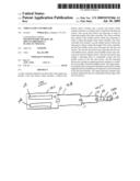
[0026]FIG. 1 illustrates a top view of the video controller 100 of the present invention.
[0027]The video controller 100 of the present invention includes a varying number of sections which telescope together in order to achieve a device which is compact and easy to carry. The number of sections can vary in accordance with the needs of the user and the particular device which is being emulated. The video controller 100 of the present invention is adaptable to be carried in a pocket, a purse, a briefcase or other suitable carrying apparatus by virtue of its compact size. The video controller 100 of the present invention can be expanded to approximate the size of a guitar or other suitable devices. If the present invention includes a telescoping portable guitar video game controller for use with the current and very popular `Guitar Hero`, `Rockband` and `Frets on Fire` video games. The controller will access a external computer, Microsoft Xbox 360, PlayStation 2 or other devices through a USB peripheral or other suitable interface for attaching to a cable or wirelessly adapted for example by using a USB wireless interface. The telescoping nature of the telescoping controller results in the telescoping controller being highly portable and suitable to be placed in a backpack, bundle pack, pocket or drawer. The present invention eliminates the need for a controller which is big and bulky and hard to carry to a location where the user may be involved in the game.
[0028]FIG. 1 illustrates a top view of the video controller 100 of the present invention. The video controller 100 includes sections 101, 103, 105, 107 which is substantially rectangular in shape and formed from substantially rigid material such as plastic or metal or other suitable material. The sections could be cylindrical or any other shape which would enhance the playing experience of the user. The video controller 100 includes a first end section 101 at a proximate end of the video controller 100 and which may include buttons or intermittent switches 109 to simulate the `strings` of a musical instrument. Additionally, the video controller 100 includes a second end section 107 at a distal end of the video controller 100 and may include finger buttons 113 which may be lighted in accordance with the controller circuit 221. FIG. 1 additionally illustrates a first middle section 103 which is slidably and detachably connected to the first end section 101 in order to telescope within the first end section 101. The first end section 101 is detachedly connected to the first middle section 103 by a fastening device 111. In a similar fashion, the second middle section 105 is slidably and detachably connected to the first middle section 103. The second middle section 105 is detachably connected to the first middle section 103 by the fastening device 111. The second end section 107 is slidably and detachably connected to the second middle section 105. The second end section 107 is detachably connected to the second middle section 105 by the fastening device 111. Each section 103, 105, 107 telescopes into another section 101, 103, 105 independently of the other sections.
[0029]FIG. 2 illustrates a side view of the first end section 101, the first middle section 103, the second middle section 105 and the second end section 107. FIG. 2 additionally illustrates the controller 221 which may be a microprocessor and an external connection device 223 for connection to an external computer for the controller 221.
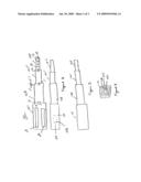
[0030]FIG. 3 illustrates a bottom view of the first end section 101, the first middle section 103, the second middle section 105 and the second end section 107. FIG. 3 illustrates that the sections 101, 103, 105, 107 have been extended.
[0031]FIG. 4 illustrates an end view of the first end section 101, the first middle section 103, the second middle section 105 and the second end section 107. FIG. 4 illustrates that each section is essentially rectangular however other profiles are within the scope of the invention such as circular, oval etc.
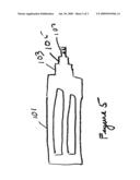
[0032]FIG. 5 illustrates a top view of the video controller 100 of the present invention. FIG. 5 illustrates that the first middle section 103 has been retracted into the first end section 101, the second middle section 105 has been retracted into the first middle section 103 and the second end section 107 has been retracted into the second middle section 105. Consequently, the overall length of the video controller 100 can be adjusted.
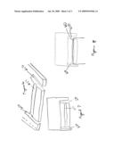
[0033]FIG. 6 illustrates a fastening device 111 which is integral with the top surface of the section 101, 103, 105 to detachably connect to an edge of extended section 103, 105, 107 respectively. FIG. 6 shows slot 650 in the longitudinal direction of the section 101, 103, 105 and along each side of the section 101, 103 and 105. FIG. 6 additionally illustrates a depression area 651 in the traverse direction between the each of the two slots 650 along each edge of the top surface. FIG. 6 illustrates the angle projection member 653 which extends along the slots 650 and is angled with respect to the top surface of the section 101, 103, 105. The angle projection member 653 detachably connects with the adjacent section 103, 105, 107 in order to hold the adjacent section 103, 105, 107 in an extended position. The user can depress the angle projection member 653 inwards in order to release the adjacent section 103, 105, 107 or the user can apply enough force that the indention will retract into the compact state to heighten the game play by allowing the user to adjust the location of the buttons 113.
[0034]In operation, the video controller 100 can be retracted by depressing the angle projection member 653 between the first and member 101 and the first middle section 103. The first middle section 103 is retracted into the first end member 101. The angle projection member 653 between the first middle section 103 and the second middle section 105 is depressed, and the second middle section 105 is retracted into the first middle member 103. The angle projection member 653 between the second middle member 105 and the second end member 107 is depressed, and the second end member 107 is retracted into the second middle member.
[0035]FIG. 7 illustrates a section 101, 103, 105 which includes an angle projection member 653 which includes a traverse depression area 651 which extends between slots 650.
[0036]FIG. 8 illustrates that the edge of the section 103, 105, 107 cooperates with the depression area 651 of section 101, 103, 105 to hold the section 103, 105, 107 in an extended position.
[0037]While the invention is susceptible to various modifications and alternative forms, specific embodiments thereof have been shown by way of example in the drawings and are herein described in detail. It should be understood, however, that the description herein of specific embodiments is not intended to limit the invention to the particular forms disclosed.
Claims:
1) A video controller adapted to be used with a video game, comprising:a
first end section which includes a fretted area; anda second end section
which includes a button and is connected to the first end section;wherein
the second end section can telescope in order to reduce the length of the
video controller.
2) A video controller adapted to be used with a video game as in claim 1, wherein the video controller includes a first middle section which may telescope in order to reduce the length of the video controller.
3) A video controller adapted to be used with a video game as in claim 2, wherein the video controller includes a second middle section which may telescope in order to reduce the length of the video controller.
4) A video controller adapted to be used with a video game as in claim 2, wherein the first middle section telescopes into the first end section.
5) A video controller adapted to be used with a video game as in claim 3, wherein the second end section telescopes into the second middle section.
6) as in claim 3, wherein the second middle section telescopes into the first middle section.
7) A video controller adapted to be used with a video game as in claim 2, wherein the first end section includes a fastening device to detachably connect the first middle section to the first end section.
8) A video controller adapted to be used with a video game as in claim 7, wherein the fastening device includes angled projection member to cooperate with an edge of the first middle section.
9) A video controller adapted to be used with a video game as in claim 8, wherein the angle projection member is integral with the first end section.
10) A video controller adapted to be used with a video game as in claim 9, wherein the angled projection member is adjacent to any slot formed in the first end member.
11) A video controller adapted to be used with a video game as in claim 10, wherein the angle projection member includes a depression area for cooperating with the edge of the first end section.
Description:
FIELD OF THE INVENTION
[0001]The present invention relates to an interactive multimedia apparatus, and more particularly to a video game controller.
BACKGROUND OF THE INVENTION
[0002]Schoolchildren, teenagers and even adults are often seen with a brush, hockey stick or tennis racket in their hand strumming along to a guitar track in the background. This is known as playing the "Air Guitar". Simulating the playing and movements of the Guitarist with the "Air Guitar" is a very important part of the musical experience, especially to songs with strong instrumental tracks. The users can fantasize and imagine themselves as the lead or bass guitarist playing in the company of their idols. Air Guitarists, however, have only a limited enjoyment experience as their action and movements do not influence the sound output in any way. There is clearly a need for a method of providing a user with a greatly enhanced musical and emotional experience using an "Air Guitar" or other "Air Instrument" when played in this way.
[0003]Videogames have provided a new dimension for entertainment.
[0004]Furthermore, music has played a part of the videogames, and consequently, there is a desire to interact with the video and music in order to provide a more realistic experience. There have been many patents directed to learning and emulating sound from a guitar.
[0005]U.S. Pat. No. 5,990,405 (Gibson Guitar Corp) discloses a system for generating and controlling a simulated musical experience in which a musician can simulate participation in a concert by playing a musical instrument and wearing a head-mounted 3D display that includes stereo speakers. Audio and video portions of a musical concert are pre-recorded, along with a separate sound track corresponding to the musical instrument played by the musician. Playback of the instrument sound track is controlled by signals generated in the musical instrument and transmitted to a system interface connected to the audio-video play back device, an audio mixer and the lead mounted display. The instrument sound track can be suppressed so that that actual sound generated by the musician playing the musical instrument can be heard with the pre-recorded audio and video portions.
[0006]The Gibson Guitar system is a specific hardware apparatus designed for use by an experienced musician and pre-supposes that the user will have access to a mixing console or decoder capable of separating a backing track audio from the composite audio. The input device is a standard electric guitar which produces analog audio signal outputs. Therefore this system is not suitable for use by an "Air Guitarist" and cannot be directed to a mass market of persons who appreciate music but have no musical training.
[0007]U.S. Pat. No. 7,151,214 to Barry discloses an apparatus which includes a guitar having strings operable by a user to generate electric signals, a control unit, storage means for a simulation backing track in any desired multi-media file format and audio/audio-visual equipment for playing a main track. The control unit has software for receiving and analyzing the electrical signals from the guitar and for synchronizing the backing track with the main track during playback. The software of the control unit opens the backing track multi-media file and streams the file in mute mode in synchronization with the main track. In response to the electrical signals from the guitar, the control unit generates an output from the multi-media file to the audio/audio-visual equipment. Alternatively, the apparatus opens and plays extracts from the multi-media file and generates an output from the multi-media files to the audio equipment together with the background track.
[0008]U.S. Pat. No. 7,064,259 to Kelly discloses a training device which includes a tubular sleeve mounted to the guitar neck. The sleeve extends along a longitudinal length of the guitar neck and has an open and a closed end portion. A plurality of light-emitting diodes are connected in series and nested within the sleeve. The light-emitting diodes extend along a length of the sleeve and are selectively illuminable. Each light-emitting diode displays one of a red color or a green color, wherein same interchangeably displays the red and green colors. A mechanism is included for automatically illuminating the light-emitting diodes in a sequence corresponding with a desired one of the chords, scales and riffs. The illuminating mechanism is coupled to the light-emitting diodes, mounted to the guitar, and includes a control switch that extends outwardly from the housing. A transformer is mateable to the illuminating mechanism for converting a 110-volt power supply to a 4.5-volt power supply.
[0009]U.S. Pat. No. 6,191,348 to Johnson discloses an institutional systems and methods for musical instruments. An array of graphic note elements are arranged on a neck of a musical instrument such that they are visible from behind or on top. The graphic note elements are controlled to indicate where a player should place his or her fingers. The player need not hold the instrument in an unnatural position while simultaneously playing the musical instrument and viewing the graphic note elements. The graphic note elements may be integrally formed on or imbedded in the back of the instrument's neck so as not to interfere with the player's hand. A control circuit is used to control the operation of the graphic elements. The control circuit may also be connected to a CD player on which control, background, and instructional data is encoded. In this case, the control circuit will control the graphic note elements using the control data, play the background data as background music to accompany the player, and/or play the instructional data in a manner that allows the player to see, hear, or feel playing instructions.
[0010]U.S. Pat. No. 6,452,081 to Ravagni discloses a device for teaching students of stringed instruments note locations and proper finger placement on the fingerboard of the instrument. The device may be adapted for use with either a fretted or non-fretted instrument. The device comprises a sheet of autogenously adhesive plastic, such as cling vinyl, within which is a set of dynamically operated markers such as LED lamps or other electro-luminescent devices for indicating fingering locations for scales or chords. Music from any source such as a recording, micro phonic pickup, synthesizer, MIDI equipment, or instrument pickups, or the like is the data input to a computer program which can denature the source music into essential components which are then reconstructed into the tonal patterns of a target instrument such as a guitar. The synthetic target instrumental music is then rendered into one or more analogs, such as a score displayed on the computer screen, recorded in the computer memory, a MIDI output, a printed score, and most importantly, to dynamically drive a set of illuminated "dots" removably attached to the finger board of a stringed instrument, thereby showing the novice player or other exactly where to place his fingers to produce the proper notes.
SUMMARY
[0011]A video controller adapted to be used with a video game may include a first end section which includes a fretted area, and a second end section which includes a button and is connected to the first end section. The second end section can telescope in order to reduce the length of the video controller. The video controller may include a first middle section which may telescope in order to reduce the length of the video controller.
[0012]The video controller may include a second middle section which may telescope in order to reduce the length of the video controller, and the first middle section may telescope into the first end section.
[0013]The second end section may telescope into the second middle section, and the second middle section may telescope into the first middle section.
[0014]The first end section may include a fastening device to detachably connect the first middle section to the first end section, and the fastening device may include an angled projection member to cooperate with an edge of the first middle section.
[0015]The angle projection member may be integral with the first end section, and the angled projection member may be adjacent to any slot formed in the first end member.
[0016]The angle projection member may include a depression area for cooperating with the edge of the first end section.
BRIEF DESCRIPTION OF THE DRAWINGS
[0017]The invention may be understood by reference to the following description taken in conjunction with the accompanying drawings, in which, like reference numerals identify like elements, and in which:
[0018]FIG. 1 illustrates a top view of the video controller of the present invention;
[0019]FIG. 2 illustrates a side view of the video controller of the present invention;
[0020]FIG. 3 illustrates a bottom view of the video controller of the present invention;
[0021]FIG. 4 illustrates a front end view of the video controller of the present invention;
[0022]FIG. 5 illustrates a top view of the video controller in a retracted position;
[0023]FIG. 6 illustrates a partial perspective view of the fastening device of the present invention;
[0024]FIG. 7 illustrates a top view of the fastening device of the present invention;
[0025]FIG. 8 illustrates the top view of the fastening device 111 cooperating with a section of the video controller.
DETAILED DESCRIPTION
[0026]FIG. 1 illustrates a top view of the video controller 100 of the present invention.
[0027]The video controller 100 of the present invention includes a varying number of sections which telescope together in order to achieve a device which is compact and easy to carry. The number of sections can vary in accordance with the needs of the user and the particular device which is being emulated. The video controller 100 of the present invention is adaptable to be carried in a pocket, a purse, a briefcase or other suitable carrying apparatus by virtue of its compact size. The video controller 100 of the present invention can be expanded to approximate the size of a guitar or other suitable devices. If the present invention includes a telescoping portable guitar video game controller for use with the current and very popular `Guitar Hero`, `Rockband` and `Frets on Fire` video games. The controller will access a external computer, Microsoft Xbox 360, PlayStation 2 or other devices through a USB peripheral or other suitable interface for attaching to a cable or wirelessly adapted for example by using a USB wireless interface. The telescoping nature of the telescoping controller results in the telescoping controller being highly portable and suitable to be placed in a backpack, bundle pack, pocket or drawer. The present invention eliminates the need for a controller which is big and bulky and hard to carry to a location where the user may be involved in the game.
[0028]FIG. 1 illustrates a top view of the video controller 100 of the present invention. The video controller 100 includes sections 101, 103, 105, 107 which is substantially rectangular in shape and formed from substantially rigid material such as plastic or metal or other suitable material. The sections could be cylindrical or any other shape which would enhance the playing experience of the user. The video controller 100 includes a first end section 101 at a proximate end of the video controller 100 and which may include buttons or intermittent switches 109 to simulate the `strings` of a musical instrument. Additionally, the video controller 100 includes a second end section 107 at a distal end of the video controller 100 and may include finger buttons 113 which may be lighted in accordance with the controller circuit 221. FIG. 1 additionally illustrates a first middle section 103 which is slidably and detachably connected to the first end section 101 in order to telescope within the first end section 101. The first end section 101 is detachedly connected to the first middle section 103 by a fastening device 111. In a similar fashion, the second middle section 105 is slidably and detachably connected to the first middle section 103. The second middle section 105 is detachably connected to the first middle section 103 by the fastening device 111. The second end section 107 is slidably and detachably connected to the second middle section 105. The second end section 107 is detachably connected to the second middle section 105 by the fastening device 111. Each section 103, 105, 107 telescopes into another section 101, 103, 105 independently of the other sections.
[0029]FIG. 2 illustrates a side view of the first end section 101, the first middle section 103, the second middle section 105 and the second end section 107. FIG. 2 additionally illustrates the controller 221 which may be a microprocessor and an external connection device 223 for connection to an external computer for the controller 221.
[0030]FIG. 3 illustrates a bottom view of the first end section 101, the first middle section 103, the second middle section 105 and the second end section 107. FIG. 3 illustrates that the sections 101, 103, 105, 107 have been extended.
[0031]FIG. 4 illustrates an end view of the first end section 101, the first middle section 103, the second middle section 105 and the second end section 107. FIG. 4 illustrates that each section is essentially rectangular however other profiles are within the scope of the invention such as circular, oval etc.
[0032]FIG. 5 illustrates a top view of the video controller 100 of the present invention. FIG. 5 illustrates that the first middle section 103 has been retracted into the first end section 101, the second middle section 105 has been retracted into the first middle section 103 and the second end section 107 has been retracted into the second middle section 105. Consequently, the overall length of the video controller 100 can be adjusted.
[0033]FIG. 6 illustrates a fastening device 111 which is integral with the top surface of the section 101, 103, 105 to detachably connect to an edge of extended section 103, 105, 107 respectively. FIG. 6 shows slot 650 in the longitudinal direction of the section 101, 103, 105 and along each side of the section 101, 103 and 105. FIG. 6 additionally illustrates a depression area 651 in the traverse direction between the each of the two slots 650 along each edge of the top surface. FIG. 6 illustrates the angle projection member 653 which extends along the slots 650 and is angled with respect to the top surface of the section 101, 103, 105. The angle projection member 653 detachably connects with the adjacent section 103, 105, 107 in order to hold the adjacent section 103, 105, 107 in an extended position. The user can depress the angle projection member 653 inwards in order to release the adjacent section 103, 105, 107 or the user can apply enough force that the indention will retract into the compact state to heighten the game play by allowing the user to adjust the location of the buttons 113.
[0034]In operation, the video controller 100 can be retracted by depressing the angle projection member 653 between the first and member 101 and the first middle section 103. The first middle section 103 is retracted into the first end member 101. The angle projection member 653 between the first middle section 103 and the second middle section 105 is depressed, and the second middle section 105 is retracted into the first middle member 103. The angle projection member 653 between the second middle member 105 and the second end member 107 is depressed, and the second end member 107 is retracted into the second middle member.
[0035]FIG. 7 illustrates a section 101, 103, 105 which includes an angle projection member 653 which includes a traverse depression area 651 which extends between slots 650.
[0036]FIG. 8 illustrates that the edge of the section 103, 105, 107 cooperates with the depression area 651 of section 101, 103, 105 to hold the section 103, 105, 107 in an extended position.
[0037]While the invention is susceptible to various modifications and alternative forms, specific embodiments thereof have been shown by way of example in the drawings and are herein described in detail. It should be understood, however, that the description herein of specific embodiments is not intended to limit the invention to the particular forms disclosed.
User Contributions:
Comment about this patent or add new information about this topic:
Images included with this patent application:
 |  |
 |  |
| Similar patent applications: | |
| Date | Title |
|---|---|
| 2008-12-18 | Video game controller |
| 2009-02-26 | Configurable single handed video game controller |
| 2009-06-18 | Video game controller with a fan |
| 2009-07-16 | Video game controller |
| 2009-08-06 | Video game controller |
| Top Inventors for class "Amusement devices: games" | |
| Rank | Inventor's name |
|---|---|
| 1 | Jay S. Walker |
| 2 | Mark B. Gagner |
| 3 | Kazumasa Yoshizawa |
| 4 | Alfred Thomas |
| 5 | Mark C. Nicely |