Patent application title: ADJUSTMENT DEVICE
Inventors:
Christian Berger (Stuttgart, DE)
Jochen Gockelmann (Salach, DE)
IPC8 Class: AF04D2700FI
USPC Class:
415145
Class name: Rotary kinetic fluid motors or pumps working fluid bypass selectively adjustable vane or working fluid control for bypass
Publication date: 2009-07-30
Patent application number: 20090191048
Inventors list |
Agents list |
Assignees list |
List by place |
Classification tree browser |
Top 100 Inventors |
Top 100 Agents |
Top 100 Assignees |
Usenet FAQ Index |
Documents |
Other FAQs |
Patent application title: ADJUSTMENT DEVICE
Inventors:
Christian Berger
Jochen Gockelmann
Agents:
RADER, FISHMAN & GRAUER PLLC
Assignees:
Origin: BLOOMFIELD HILLS, MI US
IPC8 Class: AF04D2700FI
USPC Class:
415145
Abstract:
The present invention relates to an adjustment device (1) for adjusting a
valve or a flap, in particular a pressure nozzle for actuating a bypass
valve when a limit charge pressure on an exhaust-driven turbocharger is
exceeded, which comprises a single- or multi-part housing (2), in
particular a housing (2) having a housing lower part (3) and a housing
lid. Essential to the invention is that a clip device (4) is provided, by
means of which the adjustment device (1) is fastened to a part (6).Claims:
1. An adjustment device for adjusting one of a valve and a flap, the
adjustment device being a pressure nozzle for actuating a bypass valve
when a limit charge pressure on an exhaust-driven turbocharger is
exceeded, which comprises:a housing having a housing lower part and a
housing lid, anda clip device, wherein the adjustment device is fastened
to a part by the clip device,wherein the housing is one of a single part
and a multi part housing.
2. An adjustment device according to claim 1, wherein the clip device has a clip element constructed of a plastic based material.
3. An adjustment device according to claim 2, wherein the clip element includes two sides, where a collar is on one side of the clip element and at least one latching contour is on the other side of the clip element, wherein the latching contour engages through a through-opening of the housing such that the collar bears against a housing inner side and the latching contour engages behind a counter-latching contour on the part.
4. An adjustment device according to claim 3, wherein the adjustment device has a rod-like adjustment member, which is guided through the through-opening on the housing, with the clip element surrounding the adjustment member in an annular manner.
5. An adjustment device according to claim 4, wherein the clip element, which surrounds the adjustment member (12) in an annular manner, at the same time forms a guide for the adjustment member.
6. An adjustment device according to claim 4, wherein the clip element has an annular step which forms a spring seat and is used for holding a spring which adjusts the adjustment member.
7. An adjustment device according to claim 2, wherein the clip element of the clip device is adhesively bonded to the housing of the adjustment device.
8. An adjustment device according to claim 1, further comprising a charging device that is an exhaust-driven turbocharger for a motor vehicle, which opens a bypass valve when a limit charge pressure is exceeded and thereby regulates the charge pressure.
9. An adjustment device according to claim 1, further comprising an intake system of an internal combustion engine which regulates an intake flow.
10. An adjustment device according to claim 3, wherein the through-opening is a latching opening.
11. An adjustment device according to claim 5, wherein the clip element has an annular step which forms a spring seat and is used for holding a spring which adjusts the adjustment member.
12. An adjustment device according to claim 3, wherein the clip element of the clip device is adhesively bonded to the housing of the adjustment device.
13. An adjustment device according to claim 4, wherein the clip element of the clip device is adhesively bonded to the housing of the adjustment device.
14. An adjustment device according to claim 5, wherein the clip element of the clip device is adhesively bonded to the housing of the adjustment device.
15. An adjustment device according to claim 6, wherein the clip element of the clip device is adhesively bonded to the housing of the adjustment device.
16. An adjustment device according to claim 2, further comprising a charging device that is an exhaust-driven turbocharger for a motor vehicle, which opens a bypass valve when a limit charge pressure is exceeded and thereby regulates the charge pressure.
17. An adjustment device according to claim 3, further comprising a charging device that is an exhaust-driven turbocharger for a motor vehicle, which opens a bypass valve when a limit charge pressure is exceeded and thereby regulates the charge pressure.
18. An adjustment device according to claim 2, further comprising an intake system of an internal combustion engine which regulates an intake flow.
19. An adjustment device according to claim 3, further comprising an intake system of an internal combustion engine which regulates an intake flow.
20. An adjustment device according to claim 4, further comprising an intake system of an internal combustion engine which regulates an intake flow.
Description:
[0001]The present invention relates to an adjustment device for adjusting
a valve or a flap according to the preamble of Claim 1. The invention
also relates to a charging device or an intake system of an internal
combustion engine, which device or system is equipped with such an
adjustment device.
[0002]Adjustment devices, in particular in charging devices which are configured as exhaust-driven turbochargers, are commonly known and usually have the task of opening a bypass line which bypasses the charging device as long as a charge pressure exceeds a predefined limit value. Similarly, adjustment devices are installed in intake systems of internal combustion engines, wherein they are responsible for actuating valves or flaps and help to regulate an intake flow.
[0003]DE 10 2004 058 719 A1 discloses a generic adjustment device for adjusting a valve which is installed in a charging device, which is configured as an exhaust-driven turbocharger, and opens a bypass valve when a predefined limit charge pressure is exceeded. This allows in particular an individual reaction to different operating situations of the internal combustion engine. The known adjustment device actuates what is known as a wastegate, that is, a safety or bypass valve, which diverts around the charging device, for example via a bypass line, directly into the exhaust gas system when there is a certain overpressure of the exhaust gas which drives the compressor. This diversion of the exhaust gases reduces the speed of the turbine gas of the charging device, which is transmitted to the compressor wheel so that the latter produces a lower compressor output.
[0004]The adjustment device for actuating the wastegate is usually arranged in a metallic housing outside the charging device and connected to the charging device by means of a screw-connection.
[0005]The present invention concerns itself with the problem of specifying for an adjustment device of the generic type an improved or at least a different configuration, which in particular considerably simplifies the attachment of the adjustment device to other components.
[0006]This problem is solved according to the invention by the subject matter of the independent claims. Advantageous embodiments form the subject matter of the dependent claims.
[0007]The invention is based on the general idea of no longer fixing the adjustment device for actuating a valve or a flap to another component by means of a screw-connection but by means of a clip connection. Such a clip connection considerably facilitates assembly, as it is not necessary to tighten a plurality of screws in order to fix the adjustment device, as was previously customary. The omission of these screws means furthermore that a reduction in the number of parts and thus in storage and logistics costs can be achieved. The clip connection according to the invention furthermore allows the assembly time to be reduced, as a result of which costs can likewise be reduced.
[0008]In an advantageous embodiment of the solution according to the invention, the clip device has a clip element which has a collar on one side and at least one latching contour on the other side, with which it engages through a through-opening of the housing to such an extent that the collar bears against a housing inner side and the latching contour engages behind a counter-latching contour on the part, for example a latching opening. Such a clip element, which is formed from plastic, can on the one hand be produced in an extremely cost-effective manner and in a variety of shapes and on the other hand ensures a reliable connection of the adjustment device to the associated part, for example to a housing of a charging device.
[0009]Expediently the adjustment device has a rod-like adjustment member, which is likewise guided through the through-opening on the housing, with the clip element of the clip device surrounding the adjustment member in an annular manner. The clip element can surround the adjustment member in a close, annular manner such that it at the same time forms a guide for the adjustment member. The clip element of the clip device thus fulfils a plurality of tasks, namely fixing the adjustment device to a part component on the one hand and guiding the rod-like adjustment member on the other hand. It is thus possible to represent both functions by a clip element which can be produced cost-effectively.
[0010]In a further advantageous embodiment of the invention the clip element has an annular step which forms a spring seat which is used for holding a spring which adjusts the adjustment member. The annular step further increases the functionality of the clip element according to the invention so that it can now fulfil the task of fastening the adjustment device to another part component, guiding the rod member and holding the spring. The stated functions, which previously had to fulfilled by a plurality of separate parts, can now be assumed by the plastic clip element, which can be produced cost-effectively.
[0011]Further important features and advantages of the invention can be found in the subclaims, the drawing and the associated description of the figures using the drawing.
[0012]It is self-evident that the features which are mentioned above and those which are still to be explained below can be used not only in the combination specified in each case, but also in other combinations or alone without departing from the framework of the present invention.
[0013]A preferred exemplary embodiment of the invention is shown in the drawing and explained in more detail in the following description.
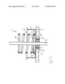
[0014]The only FIG. 1 shows a sectional diagram through an adjustment device according to the invention.
[0015]In accordance with FIG. 1, an adjustment device 1 according to the invention for adjusting a valve (not shown) or flap (likewise not shown) has a multi-part housing 2, of which only a housing lower part 3 is shown. A housing upper part of the housing 2 is not shown, wherein the adjustment device 1 can be configured for example as a pressure nozzle and is used to actuate a bypass valve when a limit charge pressure on an exhaust-driven turbocharger is exceeded. According to the invention, a clip device 4 is now provided with a clip element 5, which is used to fasten the adjustment device 1 to a part 6, for example to a housing of a charging device (not shown). The clip element 5 of the clip device 4 can for example be configured as an injection-moulded plastic part and can as a result be produced extremely cost-effectively.
[0016]As can be seen in FIG. 1, the essentially circular clip element 5 has a collar 7 on one side and at least one latching contour 8 on the other side, with which it engages through a through-opening 9 of the housing 2. The latching contour 8 which projects in the axial direction from the clip element 5 is configured to be so long that it completely engages through a through-opening 9' provided in the part 6 and engages behind an edge of the through-opening 9' in order to fasten the adjustment device 1 to the part 6. The latching contour 8 is configured to be annular and has latching lugs 10 which point radially outwards. These latching lugs 10 are arranged on elastic latching arms 11 which extend in the axial direction and allow a certain radial adjustment movement and thus a guiding of the latching lugs 10 through the through-opening 9' on the part 6. When the adjustment device 1 is completely fastened to the part 6, the collar 7 of the clip element 5 bears against a housing inner side of the housing lower part 3, so that the housing lower part 3 is clamped in a base region and the part 6 is fixed in a region which surrounds the through-opening 9' between the collar 7 of the clip element 5 on one side and the latching contours 8 on the other side.
[0017]The adjustment device 1 can, as mentioned in the introduction, be used for adjusting a valve or a flap and to this end have for example a rod-like adjustment member 12 which is likewise guided according to the configuration in FIG. 1 through the through-opening 9 on the housing and through the through-opening 9' on the part 6, with the clip element 5 surrounding the adjustment member 12 in an annular manner. A through-opening 9'' in the clip element 5, through which the adjustment member 12 is guided, can be matched to an outer diameter of the adjustment member 12 in such a manner that the clip element 5 at the same time forms a guide for the adjustment member 12.
[0018]According to FIG. 1, the clip element 5 has on its axial side which faces away from the part 6 an annular step 13 which forms a spring seat and is used for holding a spring 14 which adjusts the adjustment member 12. The spring 14 is supported against the annular step 13 of the clip element 5 and presses the latter against the base of the housing lower part 3 or against the part 6. Since the adjustment member 12 usually only transfers tensile forces, in all conceivable operating situations the spring 14 causes the clip element 5 to be pressed against the base region of the housing lower part 3. The clip element 5 thus has to absorb virtually no axial forces.
[0019]The clip device 4 according to the invention allows the adjustment device 1 to be fastened in a simple and therefore cost-effective manner to the part 6, for example to a charging device, with it being possible for both the parts costs in comparison with a screw-connection of the adjustment device 1 to the part 6 and the assembly costs to be reduced.
[0020]As the field of application for such an adjustment device 1, a charging device for example comes into consideration, with the adjustment device 1 opening a bypass valve when a limit charge pressure is exceeded and thus regulating the charge pressure of the charging device. It is likewise conceivable to use the adjustment device 1 according to the invention in an intake system of an internal combustion engine, with the adjustment device 1 in this case usually regulating an intake air flow.
User Contributions:
comments("1"); ?> comment_form("1"); ?>Inventors list |
Agents list |
Assignees list |
List by place |
Classification tree browser |
Top 100 Inventors |
Top 100 Agents |
Top 100 Assignees |
Usenet FAQ Index |
Documents |
Other FAQs |
User Contributions:
Comment about this patent or add new information about this topic:
Images included with this patent application:
 |  |
| Similar patent applications: | |
| Date | Title |
|---|---|
| 2013-08-08 | Relativistic mechanical device |
| 2013-09-26 | Diffusion type fan device |
| New patent applications in this class: | |
| Date | Title |
|---|---|
| 2019-05-16 | Gas turbine engine with mid-compressor bleed |
| 2018-01-25 | Exhaust gas turbocharger |
| 2016-07-14 | Systems and methods controlling fan pressure ratios |
| 2016-06-09 | Turbocharger combining axial flow turbine with a compressor stage utilizing active casing treatment |
| 2016-06-09 | Turbine engine assembly and method of manufacturing |
| Top Inventors for class "Rotary kinetic fluid motors or pumps" | |
| Rank | Inventor's name |
|---|---|
| 1 | Gabriel L. Suciu |
| 2 | Frederick M. Schwarz |
| 3 | United Technologies Corporation |
| 4 | Brian D. Merry |
| 5 | Craig M. Beers |