Patent application title: TOOL FOR PUSHING SNOW
Inventors:
Thomas R. Westman (Bloomfield Hills, MI, US)
Assignees:
TRW INNOVATIONS, LLC
IPC8 Class: AE01H502FI
USPC Class:
37266
Class name: Excavating snow or ice removing or grooming by portable device scraper blade
Publication date: 2009-07-30
Patent application number: 20090188136
s provided with a blade having a concave profile
along an elongate axis for pushing snow along an underlying support
surface. A handle extends generally perpendicular to the elongate axis
from an upper portion of the blade. A first contact member is provided
along a first elongate edge of the blade. The first contact member is
adapted to contact the underlying support surface in a first orientation.
A second contact member is provided along a second elongate edge of the
blade. The second contact member is adapted to contact the underlying
support surface in a second orientation.Claims:
1. A tool for pushing snow comprising:a blade having a concave profile
along an elongate axis for pushing snow along an underlying support
surface;a handle extending generally perpendicular to the elongate axis
from an upper portion of the blade;a first contact member provided along
a first elongate edge of the blade such that the first contact member is
adapted to contact the underlying support surface in a first orientation;
anda second contact member provided along a second elongate edge of the
blade such that the second contact member is adapted to contact the
underlying support surface in a second orientation.
2. The tool for pushing snow of claim 1 wherein the concave shape of the blade is further defined as semi-circular.
3. The tool for pushing snow of claim 1 wherein the second contact member further comprises a rubber blade to move liquid over the support surface in the second orientation.
4. The tool for pushing snow of claim 1 wherein the first contact member is provided along the entire first elongate edge of the blade.
5. The tool for pushing snow of claim 1 wherein the second contact member is provided along the entire second elongate edge of the blade.
6. The tool for pushing snow of claim 1 further comprising at least one support member mounted to the blade and the handle.
7. The tool for pushing snow of claim 6 wherein the at least one support member further comprises a pair of support members mounted on opposing sides of the handle.
8. The tool for pushing snow of claim 6 wherein the at least one support member is further defined as one integral support member sized to receive the handle therein.
9. The tool for pushing snow of claim 8 wherein the integral support member further defines a center bore sized to receive the handle therein to mount the handle to the blade.
10. The tool for pushing snow of claim 1 wherein the blade is formed from a polyethylene material.
11. The tool for pushing snow of claim 1 further comprising a cap mounted to the handle proximate a distal end thereof.
12. The tool for pushing snow of claim 1 wherein the handle is mounted to the support member with a plurality of removable fasteners and the support member is mounted to the blade with a plurality of removable fasteners.
13. A tool for pushing snow comprising:a semi-circular blade for pushing snow along an underlying support surface;a handle extending from the blade;a first contact member provided along a first elongate edge of the blade such that the first contact member is adapted to contact the underlying support surface in a first orientation; anda second contact member provided along a second elongate edge of the blade such that the second contact member is adapted to contact the underlying support surface in a second orientation;wherein a first arc is defined from the first elongate edge to the handle and a second arc is defined from the second elongate edge to the handle such that the first arc has a greater length than the second arc.
14. The tool for pushing snow of claim 13 wherein the handle extends generally perpendicular from the blade.
15. The tool for pushing snow of claim 13 further comprising at least one support member mounted to the blade and the handle.
16. The tool for pushing snow of claim 15 wherein the at least one support member is further defined as one integral support member sized to receive the handle therein.
17. The tool for pushing snow of claim 13 wherein the second contact member further comprises a rubber blade to move liquid over the underlying support surface in the second orientation.
18. The tool for pushing snow of claim 13 wherein the first contact member is provided along the entire first elongate edge of the blade.
19. The tool for pushing snow of claim 13 wherein the second contact member is provided along the entire second elongate edge of the blade.
20. A tool for pushing snow comprising:a semi-circular blade for pushing snow along an underlying support surface;a handle extending generally perpendicular from an upper portion of the blade;at least one support member mounted to the blade and the handle;a first contact member provided along a first elongate edge of the blade such that the first contact member is adapted to contact the underlying support surface in a first orientation; anda second contact member provided along a second elongate edge of the blade such that the second contact member is adapted to contact the underlying support surface in a second orientation, the second contact member having a rubber blade to move liquid over the underlying support surface in the second orientation;wherein a first arc is defined from the first elongate edge to the handle and a second arc is defined from the second elongate edge to the handle such that the first arc has a greater length than the second arc.Description:
CROSS-REFERENCE TO RELATED APPLICATIONS
[0001]This application claims the benefit of U.S. provisional application Ser. No. 61/024,768 filed Jan. 30, 2007; the disclosure of which is incorporated in its entirety by reference herein.
BACKGROUND
[0002]1. Technical Field
[0003]The multiple embodiments of the present invention relate to tools for pushing snow.
[0004]2. Background
[0005]In colder climates, snow often falls in the winter. Accumulations of snow on walk-ways, sidewalks, driveways or other such surfaces is generally desired to be cleared away so that the surface is free from the snow accumulations and readily traversable as usual. A person may employ a snowplow or snow shovel to clear the snow off of the surface.
BRIEF DESCRIPTION OF THE DRAWINGS
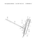
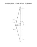
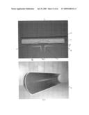
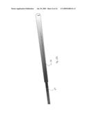
[0006]FIG. 1a is a perspective view of multiple embodiments of a tool for pushing snow;
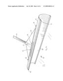
[0007]FIG. 1b is a perspective view of another embodiment of a tool for pushing snow;
[0008]FIG. 1c is an enlarged perspective view of the tool for pushing snow of FIG. 1b;
[0009]FIG. 1d is another enlarged perspective view of the tool for pushing snow of FIG. 1b;
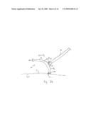
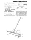
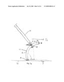
[0010]FIG. 2a is a side elevation view of an embodiment of a tool for pushing snow of FIG. 1a-d in a first orientation;
[0011]FIG. 2b is a side elevation view of another embodiment of a tool for pushing snow of FIG. 1a-d in a second orientation;
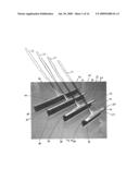
[0012]FIG. 3a is a perspective view of an embodiment of a pair of support members of a tool for pushing snow of FIGS. 1a-d;
[0013]FIG. 3b is a perspective view of another embodiment of a support member of a tool for pushing snow of FIGS. 1a-d;
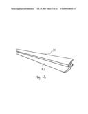
[0014]FIG. 4 is a perspective view of a first contact member of a tool for pushing snow of FIGS. 1a-1d;
[0015]FIG. 5 is a perspective view of a portion of a blade assembled with the first contact member;
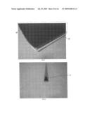
[0016]FIG. 6a is a perspective view of an embodiment of a second contact member of a tool for pushing snow of FIG. 1a-d;
[0017]FIG. 6b is a perspective view of another embodiment of a second contact member of a tool for pushing snow of FIGS. 1a-d;
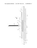
[0018]FIG. 7 is an exploded perspective view of an embodiment of a tool for pushing snow of FIG. 1a-d;
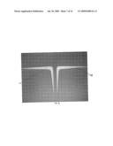
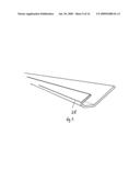
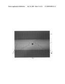
[0019]FIG. 8 is a perspective view of a blade of a tool for pushing snow of FIGS. 1a-1d;
[0020]FIG. 9 is another perspective view of a blade of a tool for pushing snow of FIG. 1a-1d;
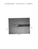
[0021]FIG. 10 is a perspective view of a portion of a handle of a tool for pushing snow of FIG. 1;
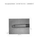
[0022]FIG. 11a is a perspective view of an embodiment of a portion of a handle of a tool for pushing snow of FIGS. 1a-d; and
[0023]FIG. 11b is a perspective view of another embodiment of a portion of a handle of a tool for pushing snow of FIGS. 1a-d.
DETAILED DESCRIPTION OF EMBODIMENTS
[0024]As required, detailed embodiments of the present invention are disclosed herein; however, it is to be understood that the disclosed embodiments are merely exemplary of the invention that may be embodied in various and alternative forms. The figures are not necessarily to scale; some features may be exaggerated or minimized to show details of particular components. Therefore, specific structural and functional details disclosed herein are not to be interpreted as limiting, but merely as a representative basis for the claims and/or as a representative basis for teaching one skilled in the art to variously employ the present invention.
[0025]Referring to FIGS. 1a-1d, tools for pushing snow are illustrated and are each generally referenced by the numeral 20. The tools 20 are useful for clearing surfaces after a light to medium amount of snow has covered the surface. These surfaces may include, but are not limited to walkways, sidewalks and driveways. To clear a small amount of snow, a user generally desires lightweight apparatus in order to exert minimal effort. The tools 20 according to the present invention are lightweight to allow for minimal exertion by the user. Additionally, the user generally desires to move a maximum amount of snow across a space of a certain size. The tools 20 have varying sizes so that the user can select an appropriate size tool 20 to move the most snow across the space having the certain size in a few amount of passes over the space with the tool 20.
[0026]In addition, when a small amount of snow accumulates on a surface, the user may not desire to plow or shovel the surface because of the effort required to plow or shovel the surface using prior art plows and shovels. Plows and shovels require the user to maneuver underneath the snow to lift and then carry the snow. Even with a small amount of snow, the effort required by a plow or shovel is great. Thus, the tool 20 is a lightweight apparatus that can move snow without requiring the user to lift and carry the snow. Additionally, the tool 20 can move liquids when orientation of the tool 10 varied by the user, which increases versatility of the tool 20.
[0027]Each tool 20 has a blade 22, which can be manufactured in varying lengths. The user can select a desired blade length for the blade 22. The user may desire a long length for the blade 22 for use across a large driveway so that the user can clean the entire driveway in minimal time with few total passes over the driveway.
[0028]As depicted in FIGS. 2a-b, the blade 22 has a concave profile along an elongate axis thereof to facilitate movement of snow without having to lift the tool 20. The blade 22 may have a semi-circular shape. In at least one embodiment, the blade 22 has an inside diameter of six inches. Of course, any suitable diameter for the blade 22 is contemplated within the scope of the present invention.
[0029]Referring now to FIGS. 1a-d and 2a-b, a handle 24 is connected to each blade 22. The handle 24 extends from the blade 22 so that the user can easily push the tool 20. In one embodiment, the handle 24 is generally perpendicular to the elongate axis of the blade 22. In another embodiment, the handle 24 is generally perpendicular to the blade 22. The handle 24 may be around sixty inches long or any other desired length. In one embodiment, the handle 24 is made out of a vinylcoated steel. In another embodiment, the handle 24 is made out of a thermoplastic. In yet another embodiment, the handle 24 is made out of a wood material. Of course, any suitable material for the handle 24 is contemplated within the scope of the present invention and multiple materials for one handle 24 may be utilized.
[0030]In one embodiment, illustrated in FIG. 2a, the handle 24 extends into a receiving aperture 32 provided within the blade 22. The handle 24 may be secured within the blade 22. The handle 24 may have a threaded engagement within the receiving aperture 32 of the blade 22. In another embodiment, the handle 24 extends through the receiving aperture 32 and beyond the blade 22. The handle 24 may be secured to the blade 22 with a fastener 34. As illustrated, the handle 24 is threaded to cooperate with a threaded nut 34. Of course, any suitable fastener 34 and any suitable amount of fasteners 34 are contemplated within the scope of the present invention.
[0031]In at least one embodiment, illustrated in FIGS. 1a-d and 2a-b, the handle 24 is supported by support members 26. The support members 26 support the connection between the blade 22 and the handle 24 to increase durability of the tool 20. In at least one embodiment, the support members 26 mount the handle 24 to the blade 22. Additionally, the support members 26 may help to ensure that the handle 24 is not disassembled from the blade 22 while in use.
[0032]As illustrated in FIG. 3a, the support members are brackets 26. As illustrated in FIG. 3b, the support member is an integrally formed bracket 26. The integrally formed bracket 26 has a center bore 33 that is sized to receive the handle 24 (as illustrated in FIGS. 1b-d). Additionally, the integrally formed bracket 26 may have apertures 27 formed therein that are sized to receive fasteners 36 to mount the integrally formed bracket 26 to the blade 22. The integrally formed bracket 26 may have an aperture 29 formed proximate the center bore 33 that is sized to receive a fastener, as discussed below. Any suitable size or shape and amount of support members 26 may be employed within the scope of the present invention.
[0033]As seen in FIGS. 1b-d and 2a-b, the support member 26 may be connected to the blade 22 and the handle 24 with fasteners 36. Any suitable fastener 26 may be utilized, such as a screw. The fasteners 36 may be removable so that the user can take the tool 20 apart as desired once assembled. In one embodiment two fasteners 36 attach the support member 26 to the blade 22 and two fasteners 36 connect the support member 26 to the handle 24. Of course, any amount of fasteners 36 may be employed to secure the support member 26 to either the blade 22 or the handle 24.
[0034]In FIGS. 1b-1d, the handle 24 is mounted to the blade 22 by the support member 26. The handle 24 is mounted within the center bore 33 (illustrated in FIG. 3b) of the support member 26 and is retained by a fastener 37. As illustrated, the fastener is a screw 37. Of course, any suitable fastener 37 and any suitable amount of fasteners 37 are contemplated within the scope of the present invention.
[0035]As seen the FIGS. 1a-d and 2a, the tool 20 is in a first orientation. The blade 22 has a first contact member 28 mounted on a first elongate edge thereof. In the first orientation illustrated, the first contact member 28 is provided to contact an underlying support surface SU so that the blade 22 is not worn away by friction as the user pushes the tool 20 across the surface SU. The first contact member 28 may also be provided to increase rigidity of the blade 22. In FIG. 4, a portion of the first contact member 28 is illustrated before attachment to the blade 22. In FIG. 5, the first contact member 28 has been mounted to the blade 22.
[0036]Referring again to FIGS. 1a-d, the first contact member 28 spans across the entire blade 22 so that the first elongate edge of the blade 22 is not exposed when assembled. In one embodiment, the first contact member 28 is mounted on the blade 22 such that the user can remove the first contact member 28 for replacement thereof. In another embodiment, the first contact member 28 may be mounted to the blade 22 with multiple fasteners. The fasteners may allow for the first contact member 28 to be permanently affixed to the blade 22. In at least one embodiment, the first contact member 28 is made of a galvanized metal. Any suitable contact member 28 may be employed to protect the blade 22 and increase rigidity of the blade 22.
[0037]With reference now specifically to FIG. 2a, one tool 20 is illustrated pushing snow S in a direction D1 across the underlying support surface SU. The handle 24 is mounted on the blade 22 such that the handle 24 located a distance X in front of the elongate edge of the blade and the first contact member 28. Locating the intersection of the handle 24 and the blade 22 the distance X in front of the first elongate edge of the blade 22 allows the user to push the tool 20 along the surface SU while moving the snow S in the forward direction D1.
[0038]Prior art snow shovels each have blades designed for gathering snow with a relation of the handle to blade such that the handle is in-line with or behind the first elongate edge of the blade, thereby producing a scooping action. The user then has to lift and/or carry the heavy snow that has accumulated on the snow shovel in order to clear the surface. The tool 20 according to the multiple embodiments of the present invention does not require the user to lift or carry the snow S, which can be very heavy and potentially hazardous to the user's health; rather, the tool 20 pushes the snow S since the first elongate edge of the blade 22 is provided the distance X behind the attachment between the handle 24 and the blade 22.
[0039]As illustrated in FIGS. 1a-d and FIGS. 2a-b, the blade 22 may have a second contact member 30 provided on an second elongate edge thereof. In at least one embodiment, the second contact 30 spans across the entire blade 22 so that the second elongate edge of the blade 22 is not exposed when assembled. The second contact member 30 may be made out of the same or different material as the first contact member 28. In one embodiment, the second contact 30 is a polyvinyl chloride material. In another embodiment, the second contact 30 is made out a rubber material. The second contact 30 can be directly mounted to the blade 22 without fasteners. In another embodiment, the second contact 30 is mounted to the blade utilizing fasteners.
[0040]The tool 20 may be placed by the user in a second orientation illustrated in FIG. 2b. In the second orientation, the second contact member 30 is contacting the support surface SU to move liquid L when the tool 20 is moved in direction D2.
[0041]In FIGS. 2a-b, a first arc A1 is defined from the first elongate edge proximate the first contact member 28 to the handle 24. A second arc A2 is defined from the second elongate edge proximate the second contact member 30 to the handle 24. As illustrated, the first arc A1 may have a greater length than the second arc A1. When the first arc A1 is greater than the second arc A2, the handle 24 has a comfortable position for pushing snow S in the first orientation illustrated in FIG. 2a. Additionally, when the tool 20 is in the second orientation, illustrated in FIG. 2b, the tool 20 can be pushed in the direction D2 easily.
[0042]An embodiment of the second contact member 30 is illustrated in detail in FIG. 6a in the second orientation. Another embodiment of the second contact member 30 is illustrated in detail in FIG. 6b in the second orientation. In FIG. 6b, the second contact member 30 has a rubber blade 31 to contact an underlying support surface. The rubber blade 31 may be provided to move liquid over the support surface in order to clean out liquids and/or slush when the tool 20 is in the second orientation, illustrated in FIG. 2b.
[0043]The tool 20 may be disassembled, which is illustrated in FIG. 7. The blade 22, the handle 24, the support members 26, and other components (such as the first contact member 28 and the second contact member 30) of the tool 20 can be manufactured separately, packaged in a small container and then shipped to the user in the disassembled orientation, which allows for easy shipment. Additionally, the user may disassemble and reassemble the tool 20, which allows for storage and/or transportation of the tool 20.
[0044]Referring now to FIGS. 8-9, an embodiment of the blade 22 is depicted in greater detail disassembled from the tool 20. The blade 22 is a semi-circle so that snow is easily moved by the tool 20, once assembled. In at least one embodiment, the blade 22 is made out of a polyethylene material so that the blade 22 and the tool 20 are light in weight. As depicted, the blade 22 has a corrugated surface so that snow our other material does not easily adhere to the surface. The blade 22 may have apertures 32, 38 formed therein, as shown in FIG. 8. The aperture 32 is sized to receive the handle 24 therein. Apertures 38 are sized to receive fasteners 36 therein to secure the support member 26 to the blade 22. The apertures 32, 38 may be integrally formed in the blade 22 or may be formed in a subsequent step after the blade 22 has already been formed.
[0045]In an embodiment shown in FIG. 10, the handle 24 has a male thread member 40 provided thereon to engage with a female thread member. In one embodiment, the female thread member is provided within the aperture of the blade 22. In another embodiment, the female thread member is a nut 34 provided on an opposite side of the blade 22 to engage the male thread member of the handle 24.
[0046]An embodiment of a portion of the handle 24 is depicted in FIG. 11a. The handle 24 has cap 42 mounted thereon to provide a molded swivel-hanging eyelet. Another embodiment of a portion of the handle 24 is depicted in FIG. 11b. The cap 42 is a foam material to provide an ergonomic grip for the user. Of course, any suitable cap 42 is contemplated within the scope of the present invention.
[0047]While embodiments of the invention have been illustrated and described, it is not intended that these embodiments illustrate and describe all possible forms of the invention. Rather, the words used in the specification are words of description rather than limitation, and it is understood that various changes may be made without departing from the spirit and scope of the invention.
Claims:
1. A tool for pushing snow comprising:a blade having a concave profile
along an elongate axis for pushing snow along an underlying support
surface;a handle extending generally perpendicular to the elongate axis
from an upper portion of the blade;a first contact member provided along
a first elongate edge of the blade such that the first contact member is
adapted to contact the underlying support surface in a first orientation;
anda second contact member provided along a second elongate edge of the
blade such that the second contact member is adapted to contact the
underlying support surface in a second orientation.
2. The tool for pushing snow of claim 1 wherein the concave shape of the blade is further defined as semi-circular.
3. The tool for pushing snow of claim 1 wherein the second contact member further comprises a rubber blade to move liquid over the support surface in the second orientation.
4. The tool for pushing snow of claim 1 wherein the first contact member is provided along the entire first elongate edge of the blade.
5. The tool for pushing snow of claim 1 wherein the second contact member is provided along the entire second elongate edge of the blade.
6. The tool for pushing snow of claim 1 further comprising at least one support member mounted to the blade and the handle.
7. The tool for pushing snow of claim 6 wherein the at least one support member further comprises a pair of support members mounted on opposing sides of the handle.
8. The tool for pushing snow of claim 6 wherein the at least one support member is further defined as one integral support member sized to receive the handle therein.
9. The tool for pushing snow of claim 8 wherein the integral support member further defines a center bore sized to receive the handle therein to mount the handle to the blade.
10. The tool for pushing snow of claim 1 wherein the blade is formed from a polyethylene material.
11. The tool for pushing snow of claim 1 further comprising a cap mounted to the handle proximate a distal end thereof.
12. The tool for pushing snow of claim 1 wherein the handle is mounted to the support member with a plurality of removable fasteners and the support member is mounted to the blade with a plurality of removable fasteners.
13. A tool for pushing snow comprising:a semi-circular blade for pushing snow along an underlying support surface;a handle extending from the blade;a first contact member provided along a first elongate edge of the blade such that the first contact member is adapted to contact the underlying support surface in a first orientation; anda second contact member provided along a second elongate edge of the blade such that the second contact member is adapted to contact the underlying support surface in a second orientation;wherein a first arc is defined from the first elongate edge to the handle and a second arc is defined from the second elongate edge to the handle such that the first arc has a greater length than the second arc.
14. The tool for pushing snow of claim 13 wherein the handle extends generally perpendicular from the blade.
15. The tool for pushing snow of claim 13 further comprising at least one support member mounted to the blade and the handle.
16. The tool for pushing snow of claim 15 wherein the at least one support member is further defined as one integral support member sized to receive the handle therein.
17. The tool for pushing snow of claim 13 wherein the second contact member further comprises a rubber blade to move liquid over the underlying support surface in the second orientation.
18. The tool for pushing snow of claim 13 wherein the first contact member is provided along the entire first elongate edge of the blade.
19. The tool for pushing snow of claim 13 wherein the second contact member is provided along the entire second elongate edge of the blade.
20. A tool for pushing snow comprising:a semi-circular blade for pushing snow along an underlying support surface;a handle extending generally perpendicular from an upper portion of the blade;at least one support member mounted to the blade and the handle;a first contact member provided along a first elongate edge of the blade such that the first contact member is adapted to contact the underlying support surface in a first orientation; anda second contact member provided along a second elongate edge of the blade such that the second contact member is adapted to contact the underlying support surface in a second orientation, the second contact member having a rubber blade to move liquid over the underlying support surface in the second orientation;wherein a first arc is defined from the first elongate edge to the handle and a second arc is defined from the second elongate edge to the handle such that the first arc has a greater length than the second arc.
Description:
CROSS-REFERENCE TO RELATED APPLICATIONS
[0001]This application claims the benefit of U.S. provisional application Ser. No. 61/024,768 filed Jan. 30, 2007; the disclosure of which is incorporated in its entirety by reference herein.
BACKGROUND
[0002]1. Technical Field
[0003]The multiple embodiments of the present invention relate to tools for pushing snow.
[0004]2. Background
[0005]In colder climates, snow often falls in the winter. Accumulations of snow on walk-ways, sidewalks, driveways or other such surfaces is generally desired to be cleared away so that the surface is free from the snow accumulations and readily traversable as usual. A person may employ a snowplow or snow shovel to clear the snow off of the surface.
BRIEF DESCRIPTION OF THE DRAWINGS
[0006]FIG. 1a is a perspective view of multiple embodiments of a tool for pushing snow;
[0007]FIG. 1b is a perspective view of another embodiment of a tool for pushing snow;
[0008]FIG. 1c is an enlarged perspective view of the tool for pushing snow of FIG. 1b;
[0009]FIG. 1d is another enlarged perspective view of the tool for pushing snow of FIG. 1b;
[0010]FIG. 2a is a side elevation view of an embodiment of a tool for pushing snow of FIG. 1a-d in a first orientation;
[0011]FIG. 2b is a side elevation view of another embodiment of a tool for pushing snow of FIG. 1a-d in a second orientation;
[0012]FIG. 3a is a perspective view of an embodiment of a pair of support members of a tool for pushing snow of FIGS. 1a-d;
[0013]FIG. 3b is a perspective view of another embodiment of a support member of a tool for pushing snow of FIGS. 1a-d;
[0014]FIG. 4 is a perspective view of a first contact member of a tool for pushing snow of FIGS. 1a-1d;
[0015]FIG. 5 is a perspective view of a portion of a blade assembled with the first contact member;
[0016]FIG. 6a is a perspective view of an embodiment of a second contact member of a tool for pushing snow of FIG. 1a-d;
[0017]FIG. 6b is a perspective view of another embodiment of a second contact member of a tool for pushing snow of FIGS. 1a-d;
[0018]FIG. 7 is an exploded perspective view of an embodiment of a tool for pushing snow of FIG. 1a-d;
[0019]FIG. 8 is a perspective view of a blade of a tool for pushing snow of FIGS. 1a-1d;
[0020]FIG. 9 is another perspective view of a blade of a tool for pushing snow of FIG. 1a-1d;
[0021]FIG. 10 is a perspective view of a portion of a handle of a tool for pushing snow of FIG. 1;
[0022]FIG. 11a is a perspective view of an embodiment of a portion of a handle of a tool for pushing snow of FIGS. 1a-d; and
[0023]FIG. 11b is a perspective view of another embodiment of a portion of a handle of a tool for pushing snow of FIGS. 1a-d.
DETAILED DESCRIPTION OF EMBODIMENTS
[0024]As required, detailed embodiments of the present invention are disclosed herein; however, it is to be understood that the disclosed embodiments are merely exemplary of the invention that may be embodied in various and alternative forms. The figures are not necessarily to scale; some features may be exaggerated or minimized to show details of particular components. Therefore, specific structural and functional details disclosed herein are not to be interpreted as limiting, but merely as a representative basis for the claims and/or as a representative basis for teaching one skilled in the art to variously employ the present invention.
[0025]Referring to FIGS. 1a-1d, tools for pushing snow are illustrated and are each generally referenced by the numeral 20. The tools 20 are useful for clearing surfaces after a light to medium amount of snow has covered the surface. These surfaces may include, but are not limited to walkways, sidewalks and driveways. To clear a small amount of snow, a user generally desires lightweight apparatus in order to exert minimal effort. The tools 20 according to the present invention are lightweight to allow for minimal exertion by the user. Additionally, the user generally desires to move a maximum amount of snow across a space of a certain size. The tools 20 have varying sizes so that the user can select an appropriate size tool 20 to move the most snow across the space having the certain size in a few amount of passes over the space with the tool 20.
[0026]In addition, when a small amount of snow accumulates on a surface, the user may not desire to plow or shovel the surface because of the effort required to plow or shovel the surface using prior art plows and shovels. Plows and shovels require the user to maneuver underneath the snow to lift and then carry the snow. Even with a small amount of snow, the effort required by a plow or shovel is great. Thus, the tool 20 is a lightweight apparatus that can move snow without requiring the user to lift and carry the snow. Additionally, the tool 20 can move liquids when orientation of the tool 10 varied by the user, which increases versatility of the tool 20.
[0027]Each tool 20 has a blade 22, which can be manufactured in varying lengths. The user can select a desired blade length for the blade 22. The user may desire a long length for the blade 22 for use across a large driveway so that the user can clean the entire driveway in minimal time with few total passes over the driveway.
[0028]As depicted in FIGS. 2a-b, the blade 22 has a concave profile along an elongate axis thereof to facilitate movement of snow without having to lift the tool 20. The blade 22 may have a semi-circular shape. In at least one embodiment, the blade 22 has an inside diameter of six inches. Of course, any suitable diameter for the blade 22 is contemplated within the scope of the present invention.
[0029]Referring now to FIGS. 1a-d and 2a-b, a handle 24 is connected to each blade 22. The handle 24 extends from the blade 22 so that the user can easily push the tool 20. In one embodiment, the handle 24 is generally perpendicular to the elongate axis of the blade 22. In another embodiment, the handle 24 is generally perpendicular to the blade 22. The handle 24 may be around sixty inches long or any other desired length. In one embodiment, the handle 24 is made out of a vinylcoated steel. In another embodiment, the handle 24 is made out of a thermoplastic. In yet another embodiment, the handle 24 is made out of a wood material. Of course, any suitable material for the handle 24 is contemplated within the scope of the present invention and multiple materials for one handle 24 may be utilized.
[0030]In one embodiment, illustrated in FIG. 2a, the handle 24 extends into a receiving aperture 32 provided within the blade 22. The handle 24 may be secured within the blade 22. The handle 24 may have a threaded engagement within the receiving aperture 32 of the blade 22. In another embodiment, the handle 24 extends through the receiving aperture 32 and beyond the blade 22. The handle 24 may be secured to the blade 22 with a fastener 34. As illustrated, the handle 24 is threaded to cooperate with a threaded nut 34. Of course, any suitable fastener 34 and any suitable amount of fasteners 34 are contemplated within the scope of the present invention.
[0031]In at least one embodiment, illustrated in FIGS. 1a-d and 2a-b, the handle 24 is supported by support members 26. The support members 26 support the connection between the blade 22 and the handle 24 to increase durability of the tool 20. In at least one embodiment, the support members 26 mount the handle 24 to the blade 22. Additionally, the support members 26 may help to ensure that the handle 24 is not disassembled from the blade 22 while in use.
[0032]As illustrated in FIG. 3a, the support members are brackets 26. As illustrated in FIG. 3b, the support member is an integrally formed bracket 26. The integrally formed bracket 26 has a center bore 33 that is sized to receive the handle 24 (as illustrated in FIGS. 1b-d). Additionally, the integrally formed bracket 26 may have apertures 27 formed therein that are sized to receive fasteners 36 to mount the integrally formed bracket 26 to the blade 22. The integrally formed bracket 26 may have an aperture 29 formed proximate the center bore 33 that is sized to receive a fastener, as discussed below. Any suitable size or shape and amount of support members 26 may be employed within the scope of the present invention.
[0033]As seen in FIGS. 1b-d and 2a-b, the support member 26 may be connected to the blade 22 and the handle 24 with fasteners 36. Any suitable fastener 26 may be utilized, such as a screw. The fasteners 36 may be removable so that the user can take the tool 20 apart as desired once assembled. In one embodiment two fasteners 36 attach the support member 26 to the blade 22 and two fasteners 36 connect the support member 26 to the handle 24. Of course, any amount of fasteners 36 may be employed to secure the support member 26 to either the blade 22 or the handle 24.
[0034]In FIGS. 1b-1d, the handle 24 is mounted to the blade 22 by the support member 26. The handle 24 is mounted within the center bore 33 (illustrated in FIG. 3b) of the support member 26 and is retained by a fastener 37. As illustrated, the fastener is a screw 37. Of course, any suitable fastener 37 and any suitable amount of fasteners 37 are contemplated within the scope of the present invention.
[0035]As seen the FIGS. 1a-d and 2a, the tool 20 is in a first orientation. The blade 22 has a first contact member 28 mounted on a first elongate edge thereof. In the first orientation illustrated, the first contact member 28 is provided to contact an underlying support surface SU so that the blade 22 is not worn away by friction as the user pushes the tool 20 across the surface SU. The first contact member 28 may also be provided to increase rigidity of the blade 22. In FIG. 4, a portion of the first contact member 28 is illustrated before attachment to the blade 22. In FIG. 5, the first contact member 28 has been mounted to the blade 22.
[0036]Referring again to FIGS. 1a-d, the first contact member 28 spans across the entire blade 22 so that the first elongate edge of the blade 22 is not exposed when assembled. In one embodiment, the first contact member 28 is mounted on the blade 22 such that the user can remove the first contact member 28 for replacement thereof. In another embodiment, the first contact member 28 may be mounted to the blade 22 with multiple fasteners. The fasteners may allow for the first contact member 28 to be permanently affixed to the blade 22. In at least one embodiment, the first contact member 28 is made of a galvanized metal. Any suitable contact member 28 may be employed to protect the blade 22 and increase rigidity of the blade 22.
[0037]With reference now specifically to FIG. 2a, one tool 20 is illustrated pushing snow S in a direction D1 across the underlying support surface SU. The handle 24 is mounted on the blade 22 such that the handle 24 located a distance X in front of the elongate edge of the blade and the first contact member 28. Locating the intersection of the handle 24 and the blade 22 the distance X in front of the first elongate edge of the blade 22 allows the user to push the tool 20 along the surface SU while moving the snow S in the forward direction D1.
[0038]Prior art snow shovels each have blades designed for gathering snow with a relation of the handle to blade such that the handle is in-line with or behind the first elongate edge of the blade, thereby producing a scooping action. The user then has to lift and/or carry the heavy snow that has accumulated on the snow shovel in order to clear the surface. The tool 20 according to the multiple embodiments of the present invention does not require the user to lift or carry the snow S, which can be very heavy and potentially hazardous to the user's health; rather, the tool 20 pushes the snow S since the first elongate edge of the blade 22 is provided the distance X behind the attachment between the handle 24 and the blade 22.
[0039]As illustrated in FIGS. 1a-d and FIGS. 2a-b, the blade 22 may have a second contact member 30 provided on an second elongate edge thereof. In at least one embodiment, the second contact 30 spans across the entire blade 22 so that the second elongate edge of the blade 22 is not exposed when assembled. The second contact member 30 may be made out of the same or different material as the first contact member 28. In one embodiment, the second contact 30 is a polyvinyl chloride material. In another embodiment, the second contact 30 is made out a rubber material. The second contact 30 can be directly mounted to the blade 22 without fasteners. In another embodiment, the second contact 30 is mounted to the blade utilizing fasteners.
[0040]The tool 20 may be placed by the user in a second orientation illustrated in FIG. 2b. In the second orientation, the second contact member 30 is contacting the support surface SU to move liquid L when the tool 20 is moved in direction D2.
[0041]In FIGS. 2a-b, a first arc A1 is defined from the first elongate edge proximate the first contact member 28 to the handle 24. A second arc A2 is defined from the second elongate edge proximate the second contact member 30 to the handle 24. As illustrated, the first arc A1 may have a greater length than the second arc A1. When the first arc A1 is greater than the second arc A2, the handle 24 has a comfortable position for pushing snow S in the first orientation illustrated in FIG. 2a. Additionally, when the tool 20 is in the second orientation, illustrated in FIG. 2b, the tool 20 can be pushed in the direction D2 easily.
[0042]An embodiment of the second contact member 30 is illustrated in detail in FIG. 6a in the second orientation. Another embodiment of the second contact member 30 is illustrated in detail in FIG. 6b in the second orientation. In FIG. 6b, the second contact member 30 has a rubber blade 31 to contact an underlying support surface. The rubber blade 31 may be provided to move liquid over the support surface in order to clean out liquids and/or slush when the tool 20 is in the second orientation, illustrated in FIG. 2b.
[0043]The tool 20 may be disassembled, which is illustrated in FIG. 7. The blade 22, the handle 24, the support members 26, and other components (such as the first contact member 28 and the second contact member 30) of the tool 20 can be manufactured separately, packaged in a small container and then shipped to the user in the disassembled orientation, which allows for easy shipment. Additionally, the user may disassemble and reassemble the tool 20, which allows for storage and/or transportation of the tool 20.
[0044]Referring now to FIGS. 8-9, an embodiment of the blade 22 is depicted in greater detail disassembled from the tool 20. The blade 22 is a semi-circle so that snow is easily moved by the tool 20, once assembled. In at least one embodiment, the blade 22 is made out of a polyethylene material so that the blade 22 and the tool 20 are light in weight. As depicted, the blade 22 has a corrugated surface so that snow our other material does not easily adhere to the surface. The blade 22 may have apertures 32, 38 formed therein, as shown in FIG. 8. The aperture 32 is sized to receive the handle 24 therein. Apertures 38 are sized to receive fasteners 36 therein to secure the support member 26 to the blade 22. The apertures 32, 38 may be integrally formed in the blade 22 or may be formed in a subsequent step after the blade 22 has already been formed.
[0045]In an embodiment shown in FIG. 10, the handle 24 has a male thread member 40 provided thereon to engage with a female thread member. In one embodiment, the female thread member is provided within the aperture of the blade 22. In another embodiment, the female thread member is a nut 34 provided on an opposite side of the blade 22 to engage the male thread member of the handle 24.
[0046]An embodiment of a portion of the handle 24 is depicted in FIG. 11a. The handle 24 has cap 42 mounted thereon to provide a molded swivel-hanging eyelet. Another embodiment of a portion of the handle 24 is depicted in FIG. 11b. The cap 42 is a foam material to provide an ergonomic grip for the user. Of course, any suitable cap 42 is contemplated within the scope of the present invention.
[0047]While embodiments of the invention have been illustrated and described, it is not intended that these embodiments illustrate and describe all possible forms of the invention. Rather, the words used in the specification are words of description rather than limitation, and it is understood that various changes may be made without departing from the spirit and scope of the invention.
User Contributions:
Comment about this patent or add new information about this topic:
Images included with this patent application:
 |  |
 |  |
 |  |
 |  |
 |  |
 |  |
 |  |
 |  |
 |
| Similar patent applications: | |
| Date | Title |
|---|---|
| 2009-02-05 | Foundation construction device for producing trenches in the soil |
| 2010-08-19 | Mulitfunctional device for clearing snow |
| 2012-01-26 | Snow plow for adjusting to surface contours and obstacles |
| 2012-03-08 | Tool control system having configuration detection |
| 2009-02-19 | Hydraulic control system for a swiveling construction machine |
| New patent applications in this class: | |
| Date | Title |
|---|---|
| 2016-05-05 | Cutting edge attachment for snow plow |
| 2016-05-05 | Compact pulling apparatus |
| 2016-02-11 | Scraper blade device for cleaning a surface and method |
| 2015-11-05 | Curbstone deflector for a snow-clearing strip |
| 2014-12-25 | Elastomeric plow edge |
| Top Inventors for class "Excavating" | |
| Rank | Inventor's name |
|---|---|
| 1 | James Robert Lahood |
| 2 | Phillip J. Kunz |
| 3 | Robert N. Gamble, Ii |
| 4 | Mark D. Buckbee |
| 5 | Kent Winter |