Patent application title: Method For Model-Based Diagnosis Of A Mechatronic System
Inventors:
Walter Lehle (Leinfelden, DE)
Jochen Assfalg (Stuttgart, DE)
Martin Fritz (Tamm, DE)
Frank Allgoewer (Stuttgart, DE)
Assignees:
Robert Bosch GMBH
IPC8 Class: AG07C500FI
USPC Class:
701 35
Class name: Vehicle control, guidance, operation, or indication vehicle diagnosis or maintenance indication with data recording device
Publication date: 2009-07-23
Patent application number: 20090187303
diagnosis of a mechatronic system. A control unit
within the mechatronic system performs error detection and an arithmetic
unit outside of the mechatronic system performs error identification.Claims:
1-10. (canceled)
11. A method for model-based diagnosis of a mechatronic system, comprising:performing error detection via a control unit within the mechatronic system; andperforming error identification via an arithmetic unit outside of the mechatronic system.
12. The method as recited in claim 11, further comprising:combining error detection data and error identification data into a complete error diagnosis.
13. The method as recited in claim 11, wherein in the case of error detection, values for input signals from system inputs and actual values for output signals from system outputs and a time vector are stored under detection control.
14. The method as recited in claim 13, wherein in the case of error detection, a setpoint value for the output variable is subtracted from an actual value of an output signal of the mechatronic system to form a residue, an error being detected if an absolute value of the residue exceeds a maximum allowable detection threshold value.
15. The method as recited in claim 11, further comprising:storing signals during a time segment which surrounds a direct point in time of an error occurrence under detection control based on a ring memory principle.
16. The method as recited in claim 15, wherein information-containing values of signals occurring within the time segment are selected.
17. The method as recited in claim 11, wherein data recorded during the error detection are read out of the control unit within the mechatronic system via a diagnostic interface and transferred to the arithmetic unit outside of the mechatronic system.
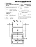
18. A diagnostic system for model-based diagnosis of a mechatronic system, comprising:a control unit situated within the mechatronic system; andan arithmetic unit situated outside of the mechatronic system;wherein the control unit is adapted for error detection of errors occurring in the mechatronic system, and the arithmetic unit is adapted for error identification of detected errors.
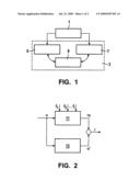
19. A storage medium storing a computer program, the computer program, when executed by a computer, causing the computer to control a mechatronic system to perform the following steps:performing error detection via a control unit within the mechatronic system; andperforming error identification via an arithmetic unit outside of the mechatronic system.
20. A computer program product storing a program code on a computer-readable data medium, the program code, when executed by a computer, causing the computer to control a mechatronic system to perform the following steps:performing error detection via a control unit within the mechatronic system; andperforming error identification via an arithmetic unit outside of the mechatronic system.Description:
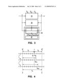
[0001]The present invention relates to a method for model-based diagnosis
of a mechatronic system, a diagnostic system, a computer program, and a
computer program product.
BACKGROUND INFORMATION
[0002]Error diagnoses for managing complex mechatronic systems require model-based diagnostic procedures. Depending on whether a model-based diagnostic function or a model-based diagnostic algorithm is calculated on-board (on-line), i.e., within the system, or off-board (off-line), i.e., outside of the system, a differentiation is made between two basic diagnostic concepts, namely on-board error diagnosis and off-board error diagnosis.
[0003]In principle, only a traditional on-board error diagnosis is capable of ensuring an unambiguous error diagnosis based on complete informational content concerning a time behavior of a faulty system. However, this is not feasible in complex mechatronic systems due to stringent real-time requirements and the simultaneously marginally available computational power in present-day control units.
[0004]Off-board error diagnosis represents a compromise which does allow computational implementation of even complex diagnostic algorithms; however, in principle, it only operates with incomplete informational content of the time behavior of the faulty system. The achievable quality of off-board diagnosis therefore turns out to be generally lower than in the case of on-board error diagnosis. Sporadically occurring errors such as, for example, intermittent interruptions due to rain water in electrical plug contacts, freezing of movable mechanical elements, overheating due to unforeseen system load, etc., cannot be diagnosed reliably; in addition, off-board error diagnosis is unambiguous only in specific error cases.
[0005]Publication DE 103 33 171 A1 describes a model-based diagnostic method for monitoring a subsystem of a machine. A quantitative model of the subsystem is used and an event-discrete analysis of the behavior of output signals is performed using qualitative values.
[0006]Against this background, a method having the features of claim 1, a diagnostic system having the features of claim 8, a computer program having the features of claim 9, and a computer program product having the features of claim 10 are described.
ADVANTAGE OF THE INVENTION
[0007]In the method of the present invention for model-based diagnosis of a mechatronic system, it is provided that a control unit within the mechatronic system performs error detection and an arithmetic unit outside of the mechatronic system performs error identification.
[0008]Additional advantageous embodiments are described in the subclaims.
[0009]The diagnostic system according to the present invention for model-based diagnosis of a mechatronic system has a control unit situated within the mechatronic system and an arithmetic unit situated outside of the mechatronic system. The control unit is designed for detection of errors occurring in the mechatronic system and the arithmetic unit is designed for identifying detected errors.
[0010]Thus a novel diagnostic concept, a comprehensive on-off-board concept is provided that combines the advantages of an on-board diagnosis and those of an off-board diagnosis. This concept makes a diagnosis possible which is based on complete informational content of the on-board diagnosis and which may be used for implementing an error diagnosis of complex mechatronic systems computationally.
[0011]A diagnostic task is divided into a not computation-intensive error detection subtask and a computation-intensive error identification subtask. In error detection, the control unit within the mechatronic system is used to determine if an error is present at a specific point in time tF. In error identification, a powerful external arithmetic unit, for example a diagnostic tester, is used to unambiguously identify an error detected using a diagnostic function.
[0012]One aspect of the present invention is that a specific sequence of temporarily stored data for input and output variables as well as time intervals may be permanently stored in a ring memory. A detection-controlled data transfer between the temporary and the permanent memories allows an intelligent selection of data containing information. In this manner, adequate information for diagnosis is available while the data volume to be stored is simultaneously limited.
[0013]By dividing the diagnostic tasks, it is possible to use advantages of both on-board diagnosis and off-board diagnosis.
[0014]The error detection to be performed on-board may thus take place under real operating conditions, taking into consideration sporadic errors that, for example, are not reproducible in a workshop. In addition, a development of an error over time may be observed, via which it is possible to obtain additional information concerning this error.
[0015]For the error identification to be performed off-board, the arithmetic unit outside of the mechatronic system has adequate computing power and storage space. In the case of error identification, no real-time requirements on the diagnostic function exist. The diagnostic function may be updated in a simple manner using updates to be implemented in the external arithmetic unit, thus making reprogramming of the control unit unnecessary.
[0016]The computer program according to the present invention having program-code means is provided for carrying out all steps of the method according to the present invention, if the computer program is run on a computer or a corresponding arithmetic unit, in particular in the diagnostic system of the present invention.
[0017]The computer program product of the present invention having program-code means that are stored on a computer-readable data medium is provided for implementing all steps of the method of the present invention when the computer program is run on a computer or a corresponding computational diagnostic system, in particular in the diagnostic system of the present invention.
[0018]Additional advantages and embodiments of the invention may be found in the description and the accompanying drawing.
[0019]Of course, the features stated above and the features still to be explained below are usable not only in the particular combination specified but also in other combinations or alone without departing from the framework of the present invention.
EXEMPLARY EMBODIMENT
[0020]The present invention is depicted schematically in the drawing based on an exemplary embodiment and will be described in greater detail below with reference to the drawing.
[0021]FIG. 1 shows a diagram for distributing diagnostic tasks.
[0022]FIG. 2 shows a diagram for an error detection.
[0023]FIG. 3 shows a diagram for a detection-controlled storage of input and output signals.
[0024]FIG. 4 shows a diagram for a chronological sequence of a memory process when an error occurs.
[0025]The diagram in FIG. 1 illustrates how a task 1 of an error diagnosis 3 is divided into an on-board error detection 5 and an off-board error detection 7. Data or signals of errors that occur within a mechatronic system and are detected by error detection 5 are stored using detection-controlled signal memory 9, which is implemented as a ring memory.
[0026]FIG. 2 shows how errors f1, f2, fi that may occur during the operation of a mechatronic system 11 are detected. In this case, a diagnostic problem is reduced to a comparison of the real faulty system 11 with a detection model 13 of the error-free system. A behavior of system 11 and detection model 13 may be compared using measured actual values y for output variables and model-generated values y' for output variables; values for input variables are identified as u. Residues may be generated based either on a model or on signals. An error f1, f2, fi is detected if an absolute value of a residue r exceeds a maximum allowable detection threshold value rmax.
[0027]Since the effects of errors f1, f2, fi may not differ from one another in the error detection, a system characteristic of detectability is by far less stringent than a system characteristic of identifiability. If a model-based error detection is performed, for example, on the basis of a model, it is already sufficient if detection model 13 reflects only the essential relationships in an input and output behavior of system 11. The detection function may therefore be implemented using simplified detection models 13 of a low degree of detailing.
[0028]FIG. 3 shows the detection-controlled storage of values u for the input signals at system inputs of system 11 or of actual values y for output signals at system outputs and of a corresponding time vector t. Values u, y of the signals contain complete information concerning a time behavior of faulty system 11. These values u, y may accordingly be stored on-board within system 11 and subsequently analyzed off-board, outside of the system.
[0029]Error detection takes place by comparing actual values y with, for example, model-generated setpoint values y' for the output variables. However, it is not absolutely necessary for the setpoint value to be generated from a model. The temporary signal memory is constantly active since it is implemented as a ring memory. As soon as an error occurs within the system and it is detected, data u, y of time period t1 are immediately transferred to the permanent memory. Data u, y of time period t2 are transferred to the permanent memory, preferably at the first possible point in time tL**.
[0030]The detection message is thus used for activating the transfer of data u, y of time period t3 from the constantly active temporary signal memory (ring memory) to the permanent memory.
[0031]Values usave, ysave, tsave for input and output variables provided for the subsequent error identification as well as the time are permanently stored, detection-controlled, in a permanent memory 17.
[0032]Since storage media even having a very high storage capacity rapidly reach their limits under sufficiently fine signal scanning, it is not possible to store values u, y of the signals over an entire operating time t of mechatronic system 11.
[0033]As shown in FIG. 4, only time segment t3 that includes a direct point in time tF of an error occurrence is relevant to the present diagnostic concept. If this time segment t3 is selected properly, it contains the complete information concerning the development of a corresponding error f over time. In the presence of a suitable synthesis of the function for error detection, a delay time between an actual error occurrence tF and a point in time of the detection of this error tD is negligibly small; tD≈tF, the assumption accordingly being tD≈tF. In the detection-controlled signal storage, it is provided to use a detection message at point in time tD as a control instruction of a memory process which determines values u, y of the signals in a relevant time segment t3, which includes point in time of error occurrence tD.
[0034]For the implementation, it is provided that one portion of the memory unit of the control unit within the mechatronic system operates from temporary signal memory 15 or an interim memory or buffer which operates according to the principle of the ring memory and another portion is formed from permanent memory 17. In this detection-controlled data transfer, a selection is made from information-containing values u, y or data from signals occurring within time segment t3.
[0035]An overwriting process of the ring memory is temporally offset into the past in relation to tF at a present point in time t*L. This ensures that informational content in u, y concerning a preceding first time segment t1 between t*L and tF of a detected error f at point in time tD is not lost by overwriting.
[0036]Furthermore, values for signals u, y for an additional second time segment t2 following tD are retained until a point in time t**L. A detection message causes temporarily stored values or data of signals u, y of information-containing time segment t3, which includes the two first fixed segments t1 and t2 between points in time t.sub.*L and t.sub.**L, to be written over from temporary memory 15 into permanent memory 17 and permanently retained there.
[0037]The data on individually documented errors f1, f2, fi retained in permanent memory 17 as part of the error detection may now be read out via a diagnostic interface so that the error identification may now take place outside of the system. The corresponding curves over time u and y as well as retained time vector t in connection with a model of faulty system behavior provide all conditions necessary for a complete management of the diagnostic task.
[0038]The present diagnostic concept is suitable for an error diagnosis of complex mechatronic systems that are operated in large numbers of units. For reasons of cost, such systems are usually operated with relatively low-performance control units. Because a model-based error diagnosis presently does not constitute a conventional control unit functionality, generally only a slight portion of the available computational power and memory capacity is available for error diagnosis.
[0039]Potential applications of the diagnostic concept are error diagnosis of passenger cars/commercial vehicles as well as of their internal combustion engines (e.g., air system applications, applications in fuel injection systems, etc.), of mechatronic chassis systems (e.g., ABS, ESP, EHB, etc.), of mechatronic industrial and automation systems as well as of packaging or thermal industrial systems.
Claims:
1-10. (canceled)
11. A method for model-based diagnosis of a mechatronic system, comprising:performing error detection via a control unit within the mechatronic system; andperforming error identification via an arithmetic unit outside of the mechatronic system.
12. The method as recited in claim 11, further comprising:combining error detection data and error identification data into a complete error diagnosis.
13. The method as recited in claim 11, wherein in the case of error detection, values for input signals from system inputs and actual values for output signals from system outputs and a time vector are stored under detection control.
14. The method as recited in claim 13, wherein in the case of error detection, a setpoint value for the output variable is subtracted from an actual value of an output signal of the mechatronic system to form a residue, an error being detected if an absolute value of the residue exceeds a maximum allowable detection threshold value.
15. The method as recited in claim 11, further comprising:storing signals during a time segment which surrounds a direct point in time of an error occurrence under detection control based on a ring memory principle.
16. The method as recited in claim 15, wherein information-containing values of signals occurring within the time segment are selected.
17. The method as recited in claim 11, wherein data recorded during the error detection are read out of the control unit within the mechatronic system via a diagnostic interface and transferred to the arithmetic unit outside of the mechatronic system.
18. A diagnostic system for model-based diagnosis of a mechatronic system, comprising:a control unit situated within the mechatronic system; andan arithmetic unit situated outside of the mechatronic system;wherein the control unit is adapted for error detection of errors occurring in the mechatronic system, and the arithmetic unit is adapted for error identification of detected errors.
19. A storage medium storing a computer program, the computer program, when executed by a computer, causing the computer to control a mechatronic system to perform the following steps:performing error detection via a control unit within the mechatronic system; andperforming error identification via an arithmetic unit outside of the mechatronic system.
20. A computer program product storing a program code on a computer-readable data medium, the program code, when executed by a computer, causing the computer to control a mechatronic system to perform the following steps:performing error detection via a control unit within the mechatronic system; andperforming error identification via an arithmetic unit outside of the mechatronic system.
Description:
[0001]The present invention relates to a method for model-based diagnosis
of a mechatronic system, a diagnostic system, a computer program, and a
computer program product.
BACKGROUND INFORMATION
[0002]Error diagnoses for managing complex mechatronic systems require model-based diagnostic procedures. Depending on whether a model-based diagnostic function or a model-based diagnostic algorithm is calculated on-board (on-line), i.e., within the system, or off-board (off-line), i.e., outside of the system, a differentiation is made between two basic diagnostic concepts, namely on-board error diagnosis and off-board error diagnosis.
[0003]In principle, only a traditional on-board error diagnosis is capable of ensuring an unambiguous error diagnosis based on complete informational content concerning a time behavior of a faulty system. However, this is not feasible in complex mechatronic systems due to stringent real-time requirements and the simultaneously marginally available computational power in present-day control units.
[0004]Off-board error diagnosis represents a compromise which does allow computational implementation of even complex diagnostic algorithms; however, in principle, it only operates with incomplete informational content of the time behavior of the faulty system. The achievable quality of off-board diagnosis therefore turns out to be generally lower than in the case of on-board error diagnosis. Sporadically occurring errors such as, for example, intermittent interruptions due to rain water in electrical plug contacts, freezing of movable mechanical elements, overheating due to unforeseen system load, etc., cannot be diagnosed reliably; in addition, off-board error diagnosis is unambiguous only in specific error cases.
[0005]Publication DE 103 33 171 A1 describes a model-based diagnostic method for monitoring a subsystem of a machine. A quantitative model of the subsystem is used and an event-discrete analysis of the behavior of output signals is performed using qualitative values.
[0006]Against this background, a method having the features of claim 1, a diagnostic system having the features of claim 8, a computer program having the features of claim 9, and a computer program product having the features of claim 10 are described.
ADVANTAGE OF THE INVENTION
[0007]In the method of the present invention for model-based diagnosis of a mechatronic system, it is provided that a control unit within the mechatronic system performs error detection and an arithmetic unit outside of the mechatronic system performs error identification.
[0008]Additional advantageous embodiments are described in the subclaims.
[0009]The diagnostic system according to the present invention for model-based diagnosis of a mechatronic system has a control unit situated within the mechatronic system and an arithmetic unit situated outside of the mechatronic system. The control unit is designed for detection of errors occurring in the mechatronic system and the arithmetic unit is designed for identifying detected errors.
[0010]Thus a novel diagnostic concept, a comprehensive on-off-board concept is provided that combines the advantages of an on-board diagnosis and those of an off-board diagnosis. This concept makes a diagnosis possible which is based on complete informational content of the on-board diagnosis and which may be used for implementing an error diagnosis of complex mechatronic systems computationally.
[0011]A diagnostic task is divided into a not computation-intensive error detection subtask and a computation-intensive error identification subtask. In error detection, the control unit within the mechatronic system is used to determine if an error is present at a specific point in time tF. In error identification, a powerful external arithmetic unit, for example a diagnostic tester, is used to unambiguously identify an error detected using a diagnostic function.
[0012]One aspect of the present invention is that a specific sequence of temporarily stored data for input and output variables as well as time intervals may be permanently stored in a ring memory. A detection-controlled data transfer between the temporary and the permanent memories allows an intelligent selection of data containing information. In this manner, adequate information for diagnosis is available while the data volume to be stored is simultaneously limited.
[0013]By dividing the diagnostic tasks, it is possible to use advantages of both on-board diagnosis and off-board diagnosis.
[0014]The error detection to be performed on-board may thus take place under real operating conditions, taking into consideration sporadic errors that, for example, are not reproducible in a workshop. In addition, a development of an error over time may be observed, via which it is possible to obtain additional information concerning this error.
[0015]For the error identification to be performed off-board, the arithmetic unit outside of the mechatronic system has adequate computing power and storage space. In the case of error identification, no real-time requirements on the diagnostic function exist. The diagnostic function may be updated in a simple manner using updates to be implemented in the external arithmetic unit, thus making reprogramming of the control unit unnecessary.
[0016]The computer program according to the present invention having program-code means is provided for carrying out all steps of the method according to the present invention, if the computer program is run on a computer or a corresponding arithmetic unit, in particular in the diagnostic system of the present invention.
[0017]The computer program product of the present invention having program-code means that are stored on a computer-readable data medium is provided for implementing all steps of the method of the present invention when the computer program is run on a computer or a corresponding computational diagnostic system, in particular in the diagnostic system of the present invention.
[0018]Additional advantages and embodiments of the invention may be found in the description and the accompanying drawing.
[0019]Of course, the features stated above and the features still to be explained below are usable not only in the particular combination specified but also in other combinations or alone without departing from the framework of the present invention.
EXEMPLARY EMBODIMENT
[0020]The present invention is depicted schematically in the drawing based on an exemplary embodiment and will be described in greater detail below with reference to the drawing.
[0021]FIG. 1 shows a diagram for distributing diagnostic tasks.
[0022]FIG. 2 shows a diagram for an error detection.
[0023]FIG. 3 shows a diagram for a detection-controlled storage of input and output signals.
[0024]FIG. 4 shows a diagram for a chronological sequence of a memory process when an error occurs.
[0025]The diagram in FIG. 1 illustrates how a task 1 of an error diagnosis 3 is divided into an on-board error detection 5 and an off-board error detection 7. Data or signals of errors that occur within a mechatronic system and are detected by error detection 5 are stored using detection-controlled signal memory 9, which is implemented as a ring memory.
[0026]FIG. 2 shows how errors f1, f2, fi that may occur during the operation of a mechatronic system 11 are detected. In this case, a diagnostic problem is reduced to a comparison of the real faulty system 11 with a detection model 13 of the error-free system. A behavior of system 11 and detection model 13 may be compared using measured actual values y for output variables and model-generated values y' for output variables; values for input variables are identified as u. Residues may be generated based either on a model or on signals. An error f1, f2, fi is detected if an absolute value of a residue r exceeds a maximum allowable detection threshold value rmax.
[0027]Since the effects of errors f1, f2, fi may not differ from one another in the error detection, a system characteristic of detectability is by far less stringent than a system characteristic of identifiability. If a model-based error detection is performed, for example, on the basis of a model, it is already sufficient if detection model 13 reflects only the essential relationships in an input and output behavior of system 11. The detection function may therefore be implemented using simplified detection models 13 of a low degree of detailing.
[0028]FIG. 3 shows the detection-controlled storage of values u for the input signals at system inputs of system 11 or of actual values y for output signals at system outputs and of a corresponding time vector t. Values u, y of the signals contain complete information concerning a time behavior of faulty system 11. These values u, y may accordingly be stored on-board within system 11 and subsequently analyzed off-board, outside of the system.
[0029]Error detection takes place by comparing actual values y with, for example, model-generated setpoint values y' for the output variables. However, it is not absolutely necessary for the setpoint value to be generated from a model. The temporary signal memory is constantly active since it is implemented as a ring memory. As soon as an error occurs within the system and it is detected, data u, y of time period t1 are immediately transferred to the permanent memory. Data u, y of time period t2 are transferred to the permanent memory, preferably at the first possible point in time tL**.
[0030]The detection message is thus used for activating the transfer of data u, y of time period t3 from the constantly active temporary signal memory (ring memory) to the permanent memory.
[0031]Values usave, ysave, tsave for input and output variables provided for the subsequent error identification as well as the time are permanently stored, detection-controlled, in a permanent memory 17.
[0032]Since storage media even having a very high storage capacity rapidly reach their limits under sufficiently fine signal scanning, it is not possible to store values u, y of the signals over an entire operating time t of mechatronic system 11.
[0033]As shown in FIG. 4, only time segment t3 that includes a direct point in time tF of an error occurrence is relevant to the present diagnostic concept. If this time segment t3 is selected properly, it contains the complete information concerning the development of a corresponding error f over time. In the presence of a suitable synthesis of the function for error detection, a delay time between an actual error occurrence tF and a point in time of the detection of this error tD is negligibly small; tD≈tF, the assumption accordingly being tD≈tF. In the detection-controlled signal storage, it is provided to use a detection message at point in time tD as a control instruction of a memory process which determines values u, y of the signals in a relevant time segment t3, which includes point in time of error occurrence tD.
[0034]For the implementation, it is provided that one portion of the memory unit of the control unit within the mechatronic system operates from temporary signal memory 15 or an interim memory or buffer which operates according to the principle of the ring memory and another portion is formed from permanent memory 17. In this detection-controlled data transfer, a selection is made from information-containing values u, y or data from signals occurring within time segment t3.
[0035]An overwriting process of the ring memory is temporally offset into the past in relation to tF at a present point in time t*L. This ensures that informational content in u, y concerning a preceding first time segment t1 between t*L and tF of a detected error f at point in time tD is not lost by overwriting.
[0036]Furthermore, values for signals u, y for an additional second time segment t2 following tD are retained until a point in time t**L. A detection message causes temporarily stored values or data of signals u, y of information-containing time segment t3, which includes the two first fixed segments t1 and t2 between points in time t.sub.*L and t.sub.**L, to be written over from temporary memory 15 into permanent memory 17 and permanently retained there.
[0037]The data on individually documented errors f1, f2, fi retained in permanent memory 17 as part of the error detection may now be read out via a diagnostic interface so that the error identification may now take place outside of the system. The corresponding curves over time u and y as well as retained time vector t in connection with a model of faulty system behavior provide all conditions necessary for a complete management of the diagnostic task.
[0038]The present diagnostic concept is suitable for an error diagnosis of complex mechatronic systems that are operated in large numbers of units. For reasons of cost, such systems are usually operated with relatively low-performance control units. Because a model-based error diagnosis presently does not constitute a conventional control unit functionality, generally only a slight portion of the available computational power and memory capacity is available for error diagnosis.
[0039]Potential applications of the diagnostic concept are error diagnosis of passenger cars/commercial vehicles as well as of their internal combustion engines (e.g., air system applications, applications in fuel injection systems, etc.), of mechatronic chassis systems (e.g., ABS, ESP, EHB, etc.), of mechatronic industrial and automation systems as well as of packaging or thermal industrial systems.
User Contributions:
Comment about this patent or add new information about this topic:
| People who visited this patent also read: | |
| Patent application number | Title |
|---|---|
| 20150119521 | AQUEOUS DISPERSIONS OF POLYURETHANE RESINS BASED ON ROSIN |
| 20150119520 | THERMATROPIC PARTICLES, METHOD FOR THE PRODUCTION AND USE THEREOF, AND DOPED POLYMERS CONTAINING SAME |
| 20150119519 | VINYL ACETATE COPOLYMERS FOR HYDRAULICALLY SETTING CONSTRUCTION MATERIALS |
| 20150119518 | EMULSION-BASED HIGH RELEASE ADDITIVE FOR RELEASE SHEET, EMULSION COMPOSITION FOR RELEASE SHEET, AND MOLD RELEASE SHEET |
| 20150119517 | Anti-Tack Powder For Uncured Rubber Pellets |
Images included with this patent application:
 |  |
 |
| New patent applications in this class: | |
| Date | Title |
|---|---|
| 2012-01-12 | Method and device for carrying out a brake test on trailer vehicles and/or semitrailer vehicles |
| 2011-12-22 | Vehicle failure diagnostic device |
| 2011-11-17 | Apparatus and method for detecting decrease in tire air pressure and program for detecting decrease in tire air pressure |
| 2011-11-10 | Antiskid control unit and data collection system for vehicle braking system |
| 2011-11-10 | Implement interface display |
| New patent applications from these inventors: | |
| Date | Title |
|---|---|
| 2018-06-07 | Method for reducing nitrogen oxide emissions of a diesel vehicle |
| 2015-10-15 | Method and system for the remotely querying vehicle data |
| 2015-06-11 | Device for monitoring a sensor of a vehicle |
| 2011-05-05 | Method and device for determining the delivery volume of an injection pump |
| Top Inventors for class "Data processing: vehicles, navigation, and relative location" | |
| Rank | Inventor's name |
|---|---|
| 1 | Anthony H. Heap |
| 2 | Ajith Kuttannair Kumar |
| 3 | Christopher P. Ricci |
| 4 | Roderick A. Hyde |
| 5 | Lowell L. Wood, Jr. |