Patent application title: ALIGNMENT AID FOR PUTTING
Inventors:
Wiestaw Kramski (Birkenfeld, DE)
Assignees:
KRAMSKI PUTTER GMBH
IPC8 Class: AA63B6936FI
USPC Class:
473407
Class name: Games using tangible projectile golf club selection, ball direction, or distance indicating aid
Publication date: 2009-07-23
Patent application number: 20090186721
ing golf having at least one first, flat section
for placing the device onto the ground, particularly in the area of the
green of a golf course, and a second section, at least arranged partially
off-set in reference to the first section so that after the placement of
the device with its first section a golf ball can be located underneath
the second section. The device is provided with an arrangement in the
second section, by which a marking applied on the golf ball is
discernible in order to check the relative alignment of the device and
the golf ball. This allows a golf ball to be aligned to a target and/or a
target alignment of the golf ball that is set can be checked.Claims:
1. A device (1) to practice playing golf, comprising at least a first,
flat section (3) adapted for placement of the device (1) on the ground,
and a second section (4), arranged at least partially off-set in
reference to the first section (3) so that after the placement of the
device (1) with the first section (3) on the ground, a golf ball (2) can
be located underneath the second section (4), and an arrangement (6)
provided at the second section (4), through which a marking (7) applied
to the golf ball (2) is discernible, in order to check a relative
alignment of the device (1) and the golf ball (2).
2. A device (1) according to claim 1, further comprising at least one visually discernible marking (9.1, 9.2, 10, 11, 12) on the device (1) for aligning the device (1) to a target location.
3. A device (1) according to claim 2, wherein the marking is embodied as a linear marking (10) provided at least in the first section (3).
4. A device (1) according to claim 2, wherein the marking is provided at a free end (11) of the first section (3) that is tapered to form a tip of an arrow.
5. A device (1) according to claim 1, further comprising a third section (5), essentially equivalent to the first section (3), with the second section (4) being arranged between the first section (3) and the third section (5).
6. A device (1) according to claim 1, wherein the second section (4) has a reduced width in reference to the first section (3).
7. A device (1) according to claim 6, wherein in at least a portion of the second section (4), the width of the device (1) is smaller than a diameter of the golf ball (2).
8. A device (1) according to claim 1, wherein the arrangement (6) for recognizing the marking (7) of the golf ball (2) comprises a slot-shaped penetration (8) in the second section.
9. A device (1) according to claim 8, wherein a length of the slot-shaped penetration (8) is approximately equal to a diameter of the golf ball (2).
10. A device (1) according to claim 8, wherein there is at least one visually discernible marking (10, 12) on at least one of the first section (3) or a third section (5) located on an opposite side of the second section from the first section, and the penetration (8) is aligned to the marking (10, 12) on the at least one of the first section (3) or the third section (5).
11. A device (1) according to claims 10, wherein at both sides of the penetration (8) additional markings (9.1, 9.2) are provided, cooperating with the marking (10, 12) on the at least one of the first section (3) or the third section (5) in a manner similar to a notch and bead.
12. A device (1) according to claim 8, wherein the second section (4), at least in a partial area, is provided with a curvature perpendicular in reference to a longitudinal extension of the device (1), which is equivalent to a curvature of a surface of the golf ball.
13. A device (1) according to claim 12, wherein the penetration (8) is arranged in the curved partial section.
14. A device (1) according to claim 8, further comprising at least one of protruding or recessed structures (13.1, 13.2) located at least in the first section (3).
15. A device (1) according to at least claim 14, wherein the at least one of protruding or recessed structures comprise the protruding structures (13.1, 13.2) that are embodied at least partially as circular arcs, with a common center of the circular arcs being arranged below the penetration (8).Description:
CROSS-REFERENCE TO RELATED APPLICATIONS
[0001]This application claims the benefit of U.S. Provisional Appln. No. 61/035,811, filed Mar. 12, 2008 and DE 20 2008 000 861.1, filed Jan. 22, 2008, both of which are incorporated herein by reference as if fully set forth.
BACKGROUND
[0002]The present invention relates to a device to practice playing golf in the form of a putting aid to check the alignment of a golf ball to the target.
[0003]In order to play a golf ball on the green of a golf course a particular club is used, the putter. Here, the position of the putter in reference to the ball and to the intended direction of putting is of decisive importance. In order to facilitate finding the correct position of the putter "square" to the ball, it has been suggested to provide golf balls with marker lines, particularly along the equator of the ball, with for example special marking devices being commercially available for this purpose. The existence of such a marking line allows a player to correctly align the putter in reference to the ball, and here the marking line shall extend perpendicularly in reference to the blade of the putter.
[0004]Although the above-described suggestion allows to find the correct position of the putter, however it fails to ensure that a subsequently performed putt actually finds its target, for example the hole or a break in the green, because here it is also necessary, in particular, that the mentioned marking line on the ball is correctly aligned to the target.
SUMMARY
[0005]The invention is based on the object of providing a device to practice playing golf by which a golf ball marked in the above-described manner can be aligned to a target and/or a set target alignment of the golf ball can be checked.
[0006]This object is provided by a device to practice playing golf having the features of the invention. Advantageous further developments of the device according to the invention are described below and recited in the claims.
[0007]Accordingly, the invention provides a device to practice playing golf having at least one first, flat section for placing the device onto the ground, particularly in the area of the green of a golf course, and a second section, at least arranged partially off-set in reference to the first section so that after the placement of the device with its first section a golf ball can be located underneath the second section, with the device being provided with an arrangement in the second section, by which a marking applied on the golf ball is discernible in order to check the relative alignment of the device and the golf ball.
[0008]When therefore the device according to the invention is placed over a golf ball and is aligned to the target, the arrangement mentioned for recognizing the markings applied to the golf ball allows checking the relative alignment of the device and the golf ball so that, on the one hand, based on the alignment of the device to the target it can be checked if the golf ball and/or its markings have been correctly aligned to the target, which for the user of the device represents a learning effect. The user can then repeat the process until a correct alignment of the ball is achieved. Alternatively, the latter can also be rotated in an aligned device such that it is aligned in the intended manner in reference to the device according to the invention and thus to the target aimed at so that it subsequently can roll in the direction of the target, particularly on its marking line.
[0009]However, the invention is not limited by any means to golf balls marked subsequently (by applying paint etc.) In general, an equator line can generally be detected in "standard" golf balls, e.g., and be used to check the described relative alignment.
[0010]In order to allow aligning the device in the direction of the target in a simple fashion a first further development of the object of the invention provides that the device is provided with at least one visually recognizable marking for an alignment to the target location, such as a hole. This visually recognizable marking can be a linear marking, particularly a colored one, applied at least on the first section.
[0011]Another further development of the device according to the invention provides that in the area of a free end of the first section serving to position the device according to the invention, said device has the form of the tip of an arrow, by which it can "target" a goal being aimed for in a particularly effective manner.
[0012]In order to allow as easily as possible handling and particularly rotating a golf ball placed underneath the device a most particularly preferred further development of the object of the invention provides that the second section is provided with at least one partial section of reduced width in reference to the first section. This can be achieved by a (multiple) narrowing of the device in the second section. In particular, the width of the device should be narrower in the second section than the typical diameter of a golf ball.
[0013]The arrangement mentioned for recognizing the golf ball marking can be embodied as a slot-shaped penetration, representing a further development of the object of the invention. Beneficially, here the slot length of the penetration can essentially be equivalent to the typical diameter of a golf ball, so that its marking is discernible over an area as large and/or complete as possible. Furthermore, the width of the slot can be equivalent to precisely the width of the marking on the golf ball.
[0014]In order to achieve an optimal alignment of the golf ball by using the device according to the invention another further development thereof provides that the penetration is aligned at least to the marking in the first section. When the device according to the invention in an appropriate further development is provided with a third section embodied similar to the first section and also provided with a marking, the penetration can and/or should additionally or alternatively also be aligned to the marking in the third section.
[0015]In order to allow an even better alignment of the device and/or the golf ball, an extremely advantageous further development of the object of the invention provides that at both sides of the penetration additional markings are applied particularly in the form of lines which at least cooperate with the marking in the first section like a notch and bead, which means that the other markings at both sides are straight and arranged next to the (virtually extended) marking in the first section. The markings mentioned can here be arranged elevated in reference to the penetration so that a real notch-structure is created.
[0016]The other markings mentioned need not be emphasized in color in reference to the remaining device. The elevated embodiment mentioned has another advantage in that the markings of the ball are (completely) discernible only in a correct alignment, which improves the training effect.
[0017]Advantageously, the second section is embodied curved, at least in a partial section, with the curvature in this area beneficially resembling a typical curvature of the surface of a golf ball. In an appropriate further development of the object of the invention then the penetration is arranged in said curved partial section. However, the present invention is not limited to such an embodiment of a second section; rather the transfer from the first section to the second section and perhaps from the second section to the third section can also occur staggered, with the second section then being embodied appropriately flat and/or level.
BRIEF DESCRIPTION OF THE DRAWINGS
[0018]Additional features and advantages of the present invention are discernible from the following description of exemplary embodiments using the drawings. Shown are:
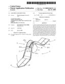
[0019]FIG. 1 is a top view of a first embodiment of the device according to the invention cooperating with a golf ball;
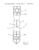
[0020]FIG. 2 is a view of the golf ball and the device of FIG. 1 from the bottom;
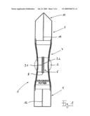
[0021]FIG. 3 is a side view of the device according to the invention according to FIG. 1; and
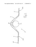
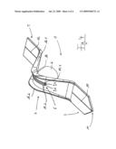
[0022]FIG. 4 is a perspective side view of the device according to FIG. 1.
DETAILED DESCRIPTION OF THE PREFERRED EMBODIMENT
[0023]FIG. 1 shows in a top view a device according to the invention to practice playing golf 1, in the following also called a putting aid, together with a golf ball 2. The putting aid 1 in its entirety has an essentially longitudinal extension and is comprised of a first, flat section 3, a second curved section 4 (cf. FIGS. 2 through 4), and a third, also flat section 5, with the second section 4 being arranged between the first section 3 and the third section 5. Based on its curvature, the second section 4 is arranged at least partially off-set in reference to the first section 3 and the third section 5, as particularly also discernible from the side view according to FIG. 3 so that after the placement of the putting aid 1, particularly in the area of the green of a golf course, the golf ball 2 is located underneath the second section 4, as shown in the attached figures.
[0024]In the embodiment of the putting aid 1 shown the flat first section 3 and the flat second section 5 serve to place the putting aid 1 on the ground, which thus is arranged like a bridge with the second section 4 above the golf ball 2. However, the present invention is not limited to such an embodiment of the putting aid 1. Rather, in a suitable embodiment of the flat section 3 or the flat section 5 it is generally also possible to waive the presence of the respectively other flat section 3, 5, for example when the respectively remaining flat section is embodied of such heavy weight that in spite of the missing other flat section a secure stand for the putting aid is ensured.
[0025]At the second section 4 the putting aid 1 is provided with an arrangement 6, through which a marking applied on the golf ball 2 is visible, in order to allow checking the relative alignment of the putting aid 1 and the golf ball 2. The above-mentioned marking on the golf ball is particularly discernible from FIG. 2, which shows the arrangement of a putting aid 1 and a golf ball 2 according to FIG. 1 from the bottom. Accordingly, the marking of the golf ball 2 represents an equator line 7 of the ball 2, which can already be applied on the golf ball 2 by the manufacturer or which can also be subsequently applied on a golf ball 2 by suitable marking devices, commercially available in specialty stores. Said marking may extend around the entire golf ball, but this is not mandatory.
[0026]In order to allow recognizing and reviewing such a marking 7 for checking the relative alignment of the putting aid 1 and the golf ball 2 after the placement of the putting aid 1 the already mentioned arrangement 6 is provided at the second section 4 of the putting aid 1, which here takes the shape of a slot-shaped penetration or window 8, which at its longitudinal sides is flanked by two linear markings 9.1, 9.2. Here, the penetration 8 and with it each of the two markings 9.1, 9.2 are arranged essentially parallel in reference to the longitudinal extension of the entire putting aid 1, as particularly discernible from FIG. 1.
[0027]In the first section 3 of the putting aid 1 another linear marking 10 is provided, which also extends parallel in reference to the longitudinal extension of the putting aid 1 and which additionally is aligned to the longitudinal extension of the penetration 8, so that it also cooperates with the markings 9.1, 9.2 like a notch and bead. The marking line 10 ends in the area of the free end 11 of the putting aid 1 and/or the first section 3, which is embodied tapering like the tip of an arrow.
[0028]In the area of the third section 5 of the putting aid 1 another linear marking 12 is provided, which is aligned both to the linear marking 10 in the first section 3 as well as the penetration 8 in the second section 4 so that the marking line 12 with the markings 9.1, 9.2 in the second section 4 also cooperate like a notch and bead.
[0029]As further discernible from FIG. 1, the second section 4 of the putting aid 1 is embodied with a reduced width in reference to the first section 3 and the third section 5, which is achieved by a narrowing of the putting aid 1 in the area of the second section 4, as shown. Here, the width of the putting aid 1 is smaller than the diameter of the golf ball 2, at least in partial sections of the second section 4, as discernible both from FIG. 1 as well as FIG. 2.
[0030]As also discernible from both FIG. 1 as well as FIG. 2, the slot length of the penetration 8, i.e. the projection of the longitudinal extension of the penetration 8 onto a level parallel in reference to the first section 3 and the third section 5 mentioned or onto a level comprising the sections 3, 5 mentioned, is essentially equivalent to the diameter of the golf ball 2. In the embodiment shown, the width of the penetration 8 essentially corresponds to the width of the markings of the equator line 7.
[0031]Furthermore, in the view according to FIG. 2 as well as the side view according to FIG. 3, net-like or grid-like structures 13.1, 13.2 are discernible at the bottom of the putting aid 1 in the area of the first section 3 and/or in the area of the third section 5. In addition to an increased stability they also contribute, in the areas mentioned, to a secure placement of the putting aid 1. The mentioned structures 13.1, 13.2 are partially embodied as circular arcs, with their common (virtual) center arranged just below the penetration 8, advantageously precisely below the center thereof. Due to the short cutting height of the lawn on the green the putting aid 1 is therefore rotational around the virtual center like on rails, which is important for its use (see the following).
[0032]It is particularly easy to learn from the side view in FIG. 3 how during its use to render playing golf easier the putting aid 1 according to the invention is positioned above the golf ball 2 such that the golf ball 2 is located underneath the second section 4 of the putting aid 1, which is elevated in reference to the ground. The putting aid 1 is here provided with a curvature perpendicular to the extension of the putting aid 1, at least in a partial section, which is essentially just equivalent to the curvature of the surface of the golf ball. Essentially straight partial sections can follow to the above-mentioned curved partial section of the second section 4 at both sides, which then converge into the flat sections 3, 5 of the putting aid 1.
[0033]Additionally, in FIG. 3 another recess 14 is discernible, in addition to the already mentioned narrowing in the apex of the second section 4, which allows a person using the putting aid 1, from the top and with his/her fingers, to simply grasp at both sides of the second section 5 a golf ball 2 positioned therebelow and to rotate it, for example, which will be discussed in greater detail in the following. The above-mentioned recesses 14 are also easily discernible from the perspective view in FIG. 4 and furthermore also serve for the ergonomic grasping of the putting aid 1.
[0034]As further discernible from the embodiment of the invention shown in FIG. 4, the penetration 8 in the second section 4 is arranged in the curved partial section of the respective section. Additionally, the markings 9.1, 9.2 already explained based on FIG. 1, are applied on respective structures 15.1, 15.2 elevated in reference to the area of the second section 4, which is equivalent to the already mentioned notch and bead principle and additionally facilitates the checking of the alignment, as described above.
[0035]Laterally the putting aid 1 is provided with elevated flank structures 16.1, 16.2 in the second section 4, which ensure greater stability and improved ergonomics, particularly in the area of the recesses 14.
[0036]The entire device according to the invention is preferably made from plastic and alternatively from a light metal or another suitable material. The markings 9.1, 9.2, 10, 12 are here emphasized by a contrasting color in reference to the material used.
[0037]In the following, potential uses of the device according to the invention to practice playing golf 1 are briefly discussed. The device according to the invention or putting aid 1 primarily serves to learn the correct alignment of a golf ball 2, marked with an equator line (cf. the marking 7 in FIG. 2), to a target. For this purpose, the golf ball 2 is first aligned "freely" so that its marking points in the direction of the target; then the putting aid 1 is placed above the golf ball 2 and is aligned via the slot or the penetration 8 in reference to the ball such that the marking line 7 on the golf ball 2 shown in FIG. 2 is located precisely underneath the penetration 8 and, if possible, can be seen over its entire length through said penetration when the player looks onto the putting aid 1 from above. If the putting aid with the tip 11 precisely points to the target the ball is correctly aligned. Otherwise the player recognizes the deviation and can realign the ball until the correct alignment has been found. This way, the device according to the invention contributes to practice or learn playing golf. By using the device according to the invention its user is able to align the golf ball 2 on the green such that it preferably rolls on its equator line in the direction of the target.
[0038]In an alternative use of the putting aid 1, the hole is aimed at with the tapering end 11 of the putting aid 1 and, if applicable, using the linear markings 10, 12 after the putting aid 1 has been placed over the golf ball 2 to be putted. For this purpose, in a further development of the putting aid 1 shown, in the area of the first section 3, additionally an elevated structure (not shown) can be arranged, particularly on the marking line 10, which then together with the elevated structures 15.1, 15.2 (cf. FIG. 4) forms a real notch and bead--arrangement for "targeting" a location, such as the hole.
[0039]After the putting aid 1 has been aligned to the target the ball 2 is rotated underneath the putting aid 1 by a lateral grasping past the narrowed second section 4 such that the marking line 7 on the golf ball 2 shown in FIG. 2 is located precisely underneath the penetration 8 and, if possible, is visible over its entire length through said penetration, when the player looks onto the putting aid 1 from above. The golf ball 2 is then aligned and/or positioned in reference to the putting aid 1 such that if putted "squarely" the ball rolls towards the target and into it, ideally precisely on its equator line.
[0040]For this purpose, in both uses the putting aid 1 must be removed prior to executing the putt, of course.
Claims:
1. A device (1) to practice playing golf, comprising at least a first,
flat section (3) adapted for placement of the device (1) on the ground,
and a second section (4), arranged at least partially off-set in
reference to the first section (3) so that after the placement of the
device (1) with the first section (3) on the ground, a golf ball (2) can
be located underneath the second section (4), and an arrangement (6)
provided at the second section (4), through which a marking (7) applied
to the golf ball (2) is discernible, in order to check a relative
alignment of the device (1) and the golf ball (2).
2. A device (1) according to claim 1, further comprising at least one visually discernible marking (9.1, 9.2, 10, 11, 12) on the device (1) for aligning the device (1) to a target location.
3. A device (1) according to claim 2, wherein the marking is embodied as a linear marking (10) provided at least in the first section (3).
4. A device (1) according to claim 2, wherein the marking is provided at a free end (11) of the first section (3) that is tapered to form a tip of an arrow.
5. A device (1) according to claim 1, further comprising a third section (5), essentially equivalent to the first section (3), with the second section (4) being arranged between the first section (3) and the third section (5).
6. A device (1) according to claim 1, wherein the second section (4) has a reduced width in reference to the first section (3).
7. A device (1) according to claim 6, wherein in at least a portion of the second section (4), the width of the device (1) is smaller than a diameter of the golf ball (2).
8. A device (1) according to claim 1, wherein the arrangement (6) for recognizing the marking (7) of the golf ball (2) comprises a slot-shaped penetration (8) in the second section.
9. A device (1) according to claim 8, wherein a length of the slot-shaped penetration (8) is approximately equal to a diameter of the golf ball (2).
10. A device (1) according to claim 8, wherein there is at least one visually discernible marking (10, 12) on at least one of the first section (3) or a third section (5) located on an opposite side of the second section from the first section, and the penetration (8) is aligned to the marking (10, 12) on the at least one of the first section (3) or the third section (5).
11. A device (1) according to claims 10, wherein at both sides of the penetration (8) additional markings (9.1, 9.2) are provided, cooperating with the marking (10, 12) on the at least one of the first section (3) or the third section (5) in a manner similar to a notch and bead.
12. A device (1) according to claim 8, wherein the second section (4), at least in a partial area, is provided with a curvature perpendicular in reference to a longitudinal extension of the device (1), which is equivalent to a curvature of a surface of the golf ball.
13. A device (1) according to claim 12, wherein the penetration (8) is arranged in the curved partial section.
14. A device (1) according to claim 8, further comprising at least one of protruding or recessed structures (13.1, 13.2) located at least in the first section (3).
15. A device (1) according to at least claim 14, wherein the at least one of protruding or recessed structures comprise the protruding structures (13.1, 13.2) that are embodied at least partially as circular arcs, with a common center of the circular arcs being arranged below the penetration (8).
Description:
CROSS-REFERENCE TO RELATED APPLICATIONS
[0001]This application claims the benefit of U.S. Provisional Appln. No. 61/035,811, filed Mar. 12, 2008 and DE 20 2008 000 861.1, filed Jan. 22, 2008, both of which are incorporated herein by reference as if fully set forth.
BACKGROUND
[0002]The present invention relates to a device to practice playing golf in the form of a putting aid to check the alignment of a golf ball to the target.
[0003]In order to play a golf ball on the green of a golf course a particular club is used, the putter. Here, the position of the putter in reference to the ball and to the intended direction of putting is of decisive importance. In order to facilitate finding the correct position of the putter "square" to the ball, it has been suggested to provide golf balls with marker lines, particularly along the equator of the ball, with for example special marking devices being commercially available for this purpose. The existence of such a marking line allows a player to correctly align the putter in reference to the ball, and here the marking line shall extend perpendicularly in reference to the blade of the putter.
[0004]Although the above-described suggestion allows to find the correct position of the putter, however it fails to ensure that a subsequently performed putt actually finds its target, for example the hole or a break in the green, because here it is also necessary, in particular, that the mentioned marking line on the ball is correctly aligned to the target.
SUMMARY
[0005]The invention is based on the object of providing a device to practice playing golf by which a golf ball marked in the above-described manner can be aligned to a target and/or a set target alignment of the golf ball can be checked.
[0006]This object is provided by a device to practice playing golf having the features of the invention. Advantageous further developments of the device according to the invention are described below and recited in the claims.
[0007]Accordingly, the invention provides a device to practice playing golf having at least one first, flat section for placing the device onto the ground, particularly in the area of the green of a golf course, and a second section, at least arranged partially off-set in reference to the first section so that after the placement of the device with its first section a golf ball can be located underneath the second section, with the device being provided with an arrangement in the second section, by which a marking applied on the golf ball is discernible in order to check the relative alignment of the device and the golf ball.
[0008]When therefore the device according to the invention is placed over a golf ball and is aligned to the target, the arrangement mentioned for recognizing the markings applied to the golf ball allows checking the relative alignment of the device and the golf ball so that, on the one hand, based on the alignment of the device to the target it can be checked if the golf ball and/or its markings have been correctly aligned to the target, which for the user of the device represents a learning effect. The user can then repeat the process until a correct alignment of the ball is achieved. Alternatively, the latter can also be rotated in an aligned device such that it is aligned in the intended manner in reference to the device according to the invention and thus to the target aimed at so that it subsequently can roll in the direction of the target, particularly on its marking line.
[0009]However, the invention is not limited by any means to golf balls marked subsequently (by applying paint etc.) In general, an equator line can generally be detected in "standard" golf balls, e.g., and be used to check the described relative alignment.
[0010]In order to allow aligning the device in the direction of the target in a simple fashion a first further development of the object of the invention provides that the device is provided with at least one visually recognizable marking for an alignment to the target location, such as a hole. This visually recognizable marking can be a linear marking, particularly a colored one, applied at least on the first section.
[0011]Another further development of the device according to the invention provides that in the area of a free end of the first section serving to position the device according to the invention, said device has the form of the tip of an arrow, by which it can "target" a goal being aimed for in a particularly effective manner.
[0012]In order to allow as easily as possible handling and particularly rotating a golf ball placed underneath the device a most particularly preferred further development of the object of the invention provides that the second section is provided with at least one partial section of reduced width in reference to the first section. This can be achieved by a (multiple) narrowing of the device in the second section. In particular, the width of the device should be narrower in the second section than the typical diameter of a golf ball.
[0013]The arrangement mentioned for recognizing the golf ball marking can be embodied as a slot-shaped penetration, representing a further development of the object of the invention. Beneficially, here the slot length of the penetration can essentially be equivalent to the typical diameter of a golf ball, so that its marking is discernible over an area as large and/or complete as possible. Furthermore, the width of the slot can be equivalent to precisely the width of the marking on the golf ball.
[0014]In order to achieve an optimal alignment of the golf ball by using the device according to the invention another further development thereof provides that the penetration is aligned at least to the marking in the first section. When the device according to the invention in an appropriate further development is provided with a third section embodied similar to the first section and also provided with a marking, the penetration can and/or should additionally or alternatively also be aligned to the marking in the third section.
[0015]In order to allow an even better alignment of the device and/or the golf ball, an extremely advantageous further development of the object of the invention provides that at both sides of the penetration additional markings are applied particularly in the form of lines which at least cooperate with the marking in the first section like a notch and bead, which means that the other markings at both sides are straight and arranged next to the (virtually extended) marking in the first section. The markings mentioned can here be arranged elevated in reference to the penetration so that a real notch-structure is created.
[0016]The other markings mentioned need not be emphasized in color in reference to the remaining device. The elevated embodiment mentioned has another advantage in that the markings of the ball are (completely) discernible only in a correct alignment, which improves the training effect.
[0017]Advantageously, the second section is embodied curved, at least in a partial section, with the curvature in this area beneficially resembling a typical curvature of the surface of a golf ball. In an appropriate further development of the object of the invention then the penetration is arranged in said curved partial section. However, the present invention is not limited to such an embodiment of a second section; rather the transfer from the first section to the second section and perhaps from the second section to the third section can also occur staggered, with the second section then being embodied appropriately flat and/or level.
BRIEF DESCRIPTION OF THE DRAWINGS
[0018]Additional features and advantages of the present invention are discernible from the following description of exemplary embodiments using the drawings. Shown are:
[0019]FIG. 1 is a top view of a first embodiment of the device according to the invention cooperating with a golf ball;
[0020]FIG. 2 is a view of the golf ball and the device of FIG. 1 from the bottom;
[0021]FIG. 3 is a side view of the device according to the invention according to FIG. 1; and
[0022]FIG. 4 is a perspective side view of the device according to FIG. 1.
DETAILED DESCRIPTION OF THE PREFERRED EMBODIMENT
[0023]FIG. 1 shows in a top view a device according to the invention to practice playing golf 1, in the following also called a putting aid, together with a golf ball 2. The putting aid 1 in its entirety has an essentially longitudinal extension and is comprised of a first, flat section 3, a second curved section 4 (cf. FIGS. 2 through 4), and a third, also flat section 5, with the second section 4 being arranged between the first section 3 and the third section 5. Based on its curvature, the second section 4 is arranged at least partially off-set in reference to the first section 3 and the third section 5, as particularly also discernible from the side view according to FIG. 3 so that after the placement of the putting aid 1, particularly in the area of the green of a golf course, the golf ball 2 is located underneath the second section 4, as shown in the attached figures.
[0024]In the embodiment of the putting aid 1 shown the flat first section 3 and the flat second section 5 serve to place the putting aid 1 on the ground, which thus is arranged like a bridge with the second section 4 above the golf ball 2. However, the present invention is not limited to such an embodiment of the putting aid 1. Rather, in a suitable embodiment of the flat section 3 or the flat section 5 it is generally also possible to waive the presence of the respectively other flat section 3, 5, for example when the respectively remaining flat section is embodied of such heavy weight that in spite of the missing other flat section a secure stand for the putting aid is ensured.
[0025]At the second section 4 the putting aid 1 is provided with an arrangement 6, through which a marking applied on the golf ball 2 is visible, in order to allow checking the relative alignment of the putting aid 1 and the golf ball 2. The above-mentioned marking on the golf ball is particularly discernible from FIG. 2, which shows the arrangement of a putting aid 1 and a golf ball 2 according to FIG. 1 from the bottom. Accordingly, the marking of the golf ball 2 represents an equator line 7 of the ball 2, which can already be applied on the golf ball 2 by the manufacturer or which can also be subsequently applied on a golf ball 2 by suitable marking devices, commercially available in specialty stores. Said marking may extend around the entire golf ball, but this is not mandatory.
[0026]In order to allow recognizing and reviewing such a marking 7 for checking the relative alignment of the putting aid 1 and the golf ball 2 after the placement of the putting aid 1 the already mentioned arrangement 6 is provided at the second section 4 of the putting aid 1, which here takes the shape of a slot-shaped penetration or window 8, which at its longitudinal sides is flanked by two linear markings 9.1, 9.2. Here, the penetration 8 and with it each of the two markings 9.1, 9.2 are arranged essentially parallel in reference to the longitudinal extension of the entire putting aid 1, as particularly discernible from FIG. 1.
[0027]In the first section 3 of the putting aid 1 another linear marking 10 is provided, which also extends parallel in reference to the longitudinal extension of the putting aid 1 and which additionally is aligned to the longitudinal extension of the penetration 8, so that it also cooperates with the markings 9.1, 9.2 like a notch and bead. The marking line 10 ends in the area of the free end 11 of the putting aid 1 and/or the first section 3, which is embodied tapering like the tip of an arrow.
[0028]In the area of the third section 5 of the putting aid 1 another linear marking 12 is provided, which is aligned both to the linear marking 10 in the first section 3 as well as the penetration 8 in the second section 4 so that the marking line 12 with the markings 9.1, 9.2 in the second section 4 also cooperate like a notch and bead.
[0029]As further discernible from FIG. 1, the second section 4 of the putting aid 1 is embodied with a reduced width in reference to the first section 3 and the third section 5, which is achieved by a narrowing of the putting aid 1 in the area of the second section 4, as shown. Here, the width of the putting aid 1 is smaller than the diameter of the golf ball 2, at least in partial sections of the second section 4, as discernible both from FIG. 1 as well as FIG. 2.
[0030]As also discernible from both FIG. 1 as well as FIG. 2, the slot length of the penetration 8, i.e. the projection of the longitudinal extension of the penetration 8 onto a level parallel in reference to the first section 3 and the third section 5 mentioned or onto a level comprising the sections 3, 5 mentioned, is essentially equivalent to the diameter of the golf ball 2. In the embodiment shown, the width of the penetration 8 essentially corresponds to the width of the markings of the equator line 7.
[0031]Furthermore, in the view according to FIG. 2 as well as the side view according to FIG. 3, net-like or grid-like structures 13.1, 13.2 are discernible at the bottom of the putting aid 1 in the area of the first section 3 and/or in the area of the third section 5. In addition to an increased stability they also contribute, in the areas mentioned, to a secure placement of the putting aid 1. The mentioned structures 13.1, 13.2 are partially embodied as circular arcs, with their common (virtual) center arranged just below the penetration 8, advantageously precisely below the center thereof. Due to the short cutting height of the lawn on the green the putting aid 1 is therefore rotational around the virtual center like on rails, which is important for its use (see the following).
[0032]It is particularly easy to learn from the side view in FIG. 3 how during its use to render playing golf easier the putting aid 1 according to the invention is positioned above the golf ball 2 such that the golf ball 2 is located underneath the second section 4 of the putting aid 1, which is elevated in reference to the ground. The putting aid 1 is here provided with a curvature perpendicular to the extension of the putting aid 1, at least in a partial section, which is essentially just equivalent to the curvature of the surface of the golf ball. Essentially straight partial sections can follow to the above-mentioned curved partial section of the second section 4 at both sides, which then converge into the flat sections 3, 5 of the putting aid 1.
[0033]Additionally, in FIG. 3 another recess 14 is discernible, in addition to the already mentioned narrowing in the apex of the second section 4, which allows a person using the putting aid 1, from the top and with his/her fingers, to simply grasp at both sides of the second section 5 a golf ball 2 positioned therebelow and to rotate it, for example, which will be discussed in greater detail in the following. The above-mentioned recesses 14 are also easily discernible from the perspective view in FIG. 4 and furthermore also serve for the ergonomic grasping of the putting aid 1.
[0034]As further discernible from the embodiment of the invention shown in FIG. 4, the penetration 8 in the second section 4 is arranged in the curved partial section of the respective section. Additionally, the markings 9.1, 9.2 already explained based on FIG. 1, are applied on respective structures 15.1, 15.2 elevated in reference to the area of the second section 4, which is equivalent to the already mentioned notch and bead principle and additionally facilitates the checking of the alignment, as described above.
[0035]Laterally the putting aid 1 is provided with elevated flank structures 16.1, 16.2 in the second section 4, which ensure greater stability and improved ergonomics, particularly in the area of the recesses 14.
[0036]The entire device according to the invention is preferably made from plastic and alternatively from a light metal or another suitable material. The markings 9.1, 9.2, 10, 12 are here emphasized by a contrasting color in reference to the material used.
[0037]In the following, potential uses of the device according to the invention to practice playing golf 1 are briefly discussed. The device according to the invention or putting aid 1 primarily serves to learn the correct alignment of a golf ball 2, marked with an equator line (cf. the marking 7 in FIG. 2), to a target. For this purpose, the golf ball 2 is first aligned "freely" so that its marking points in the direction of the target; then the putting aid 1 is placed above the golf ball 2 and is aligned via the slot or the penetration 8 in reference to the ball such that the marking line 7 on the golf ball 2 shown in FIG. 2 is located precisely underneath the penetration 8 and, if possible, can be seen over its entire length through said penetration when the player looks onto the putting aid 1 from above. If the putting aid with the tip 11 precisely points to the target the ball is correctly aligned. Otherwise the player recognizes the deviation and can realign the ball until the correct alignment has been found. This way, the device according to the invention contributes to practice or learn playing golf. By using the device according to the invention its user is able to align the golf ball 2 on the green such that it preferably rolls on its equator line in the direction of the target.
[0038]In an alternative use of the putting aid 1, the hole is aimed at with the tapering end 11 of the putting aid 1 and, if applicable, using the linear markings 10, 12 after the putting aid 1 has been placed over the golf ball 2 to be putted. For this purpose, in a further development of the putting aid 1 shown, in the area of the first section 3, additionally an elevated structure (not shown) can be arranged, particularly on the marking line 10, which then together with the elevated structures 15.1, 15.2 (cf. FIG. 4) forms a real notch and bead--arrangement for "targeting" a location, such as the hole.
[0039]After the putting aid 1 has been aligned to the target the ball 2 is rotated underneath the putting aid 1 by a lateral grasping past the narrowed second section 4 such that the marking line 7 on the golf ball 2 shown in FIG. 2 is located precisely underneath the penetration 8 and, if possible, is visible over its entire length through said penetration, when the player looks onto the putting aid 1 from above. The golf ball 2 is then aligned and/or positioned in reference to the putting aid 1 such that if putted "squarely" the ball rolls towards the target and into it, ideally precisely on its equator line.
[0040]For this purpose, in both uses the putting aid 1 must be removed prior to executing the putt, of course.
User Contributions:
Comment about this patent or add new information about this topic:
Images included with this patent application:
 |  |
 |  |
 |
| Similar patent applications: | |
| Date | Title |
|---|---|
| 2009-02-19 | Throwable chemiluminescent device suitable for impact activation |
| 2010-04-01 | Method and device for improving putting |
| 2011-03-17 | Alignment guide for a golf ball |
| 2009-06-04 | Alignment device for golfers |
| 2009-06-25 | In-field behavior recording device for golf putting |
| New patent applications in this class: | |
| Date | Title |
|---|---|
| 2016-07-14 | Coaching aid for golf |
| 2016-05-19 | Golf club fitting system and method |
| 2016-04-07 | Wearable computing devices for assisting a user in playing a round of golf |
| 2016-01-14 | Methods and systems for target maps for golf shots |
| 2015-12-03 | Golf aid including virtual caddy |
| New patent applications from these inventors: | |
| Date | Title |
|---|---|
| 2010-04-08 | Putter fitting station |
| 2009-12-10 | Positioning device for a golfer when putting |
| Top Inventors for class "Games using tangible projectile" | |
| Rank | Inventor's name |
|---|---|
| 1 | Michael J. Sullivan |
| 2 | Brian Comeau |
| 3 | Derek A. Ladd |
| 4 | David A. Bulpett |
| 5 | Mark L. Binette |