Patent application title: Self-assembly micro blade
Inventors:
Alex Horng (Kaohsiung City, TW)
I-Yu Huang (Kaohsiung City, TW)
Chung-Jen Huang (Kaohsiung City, TW)
Assignees:
SUNONWEALTH ELECTRIC MACHINE INDUSTRY CO., LTD.
IPC8 Class: AB63H120FI
USPC Class:
416220 R
Class name: Specific working member mount blade received in well or slot having blade locking means
Publication date: 2009-07-23
Patent application number: 20090185909
ates to a self-assembly micro blade applied to a
micro fan. The micro fan combines at least a self-assembly micro blade
and a motor using an actuator as the main body of the micro fan. The
self-assembly micro blade includes at least a movable part of a
microstructure, at least an elastic joint provided between an outer ring
of the micro fan and the movable part. The elastic joint is composed of a
polyimide film, which is heated to contract and generate surface tension
by using a reflow process so as to lift up the movable part of the
microstructure; moreover, the movable part is bent in a curved form
through the elastic link exhibits a multi-layer shape by serially
connecting at least two movable parts so as to complete the self assembly
of the micro blade, thereby increasing air flow rate and improving air
flow length.Claims:
1. A self-assembly micro blade, comprising:at least a movable part of a
microstructure;at least an elastic joint provided between the movable
part and an outer ring of a micro motor, and generating surface tension
to lift up the movable part of the microstructure by using a reflow
process.
2. The self-assembly micro blade as set forth in claim 1, wherein the elastic joint is a photosensing polyimide film.
3. The self-assembly micro blade as set forth in claim 1, wherein a method for manufacturing the self-assembly micro blade comprises processes of:(1) depositing a low-stress sacrifice layer on a silicon substrate and depositing a main structure layer on the low-stress sacrifice layer;(2) defining the main structure layer to etch out an overall profile of the microstructure;(3) coating a photosensing polyimide film on the main structure layer and an outer ring of the micro motor;(4) defining the polyimide film to etch out a form of an elastic joint;(5) performing wet etch to etch and release a preset portion of the low-stress sacrifice layer; and(6) performing a reflow process to heat up the elastic joint to result in thermal contraction and lifting up a preset portion of the main structure layer.
4. The self-assembly micro blade as set forth in claim 3, wherein the low-stress sacrifice layer is a phosphosilicate glass (PSG).
5. The self-assembly micro blade as set forth in claim 3, wherein the main structure layer is a polysilicon.
6. A self-assembly micro blade, comprising:at least a movable part of a microstructure; andat least an elastic joint provided between the movable part and an outer ring of a micro motor; andan elastic link provided on each movable part, so that surface tension is generated by each of the elastic joint and the elastic link through a reflow process and the movable part of the microstructure is lifted up and bent in form of curved surface;
7. The self-assembly micro blade as set forth in claim 6, wherein the elastic joint is a photosensing polyimide film.
8. The self-assembly micro blade as set forth in claim 6, wherein a first elastic joint is defined on a first side of the movable part.
9. The self-assembly micro blade as set forth in claim 6, wherein a second elastic joint is defined on a second side of the movable part.
10. The self-assembly micro blade as set forth in claim 6, wherein an elastic link is defined above the first elastic joint on each of the movable part.
11. The self-assembly micro blade as set forth in claim 6, wherein a third elastic joint is defined above the elastic link on the movable part.
12. The self-assembly micro blade as set forth in claim 6, wherein the elastic link is a photosensing polyimide film.
13. A self-assembly micro blade, comprising:at least a first movable part and a second movable part of a microstructure; andat least an elastic joint provided between the first movable part and an outer ring of a micro motor and between the first movable part and the second movable part respectively; andan elastic link is provided on each second movable part, so that surface tension is generated by each of the elastic joint and the elastic link through a reflow process and the movable part of the microstructure is lifted up and bent in form of multiple layers and curved plane.
14. The self-assembly micro blade as set forth in claim 13, wherein the elastic joint is a photosensing polyimide film.
15. The self-assembly micro blade as set forth in claim 13, wherein a first elastic joint is defined on each of the first movable part.
16. The self-assembly micro blade as set forth in claim 13, wherein a second elastic joint is defined on a first side of each of the second movable part.
17. The self-assembly micro blade as set forth in claim 13, wherein a third elastic joint is defined on a second side of each of the second movable part.
18. The self-assembly micro blade as set forth in claim 13, wherein an elastic link is defined above the second elastic joint of each of the second movable part.
19. The self-assembly micro blade as set forth in claim 13, wherein a fourth elastic joint is defined above the elastic link of each of the second movable part.
20. The self-assembly micro blade as set forth in claim 13, wherein the elastic link is a photosensing polyimide film.Description:
FIELD OF THE INVENTION
[0001]The present invention relates to a self-assembly micro blade for micro fan, which is characterized by providing additional flow rate and control and improvement of flow length so as to solve the drawbacks of conventional skill.
BACKGROUND OF THE INVENTION
[0002]Research and application of miniaturization technology is one of two major trends of modern science. In particular, self-assembly technique is a mainstream approach for assembling microstructure in microworld in recent years.
[0003]As far as a micro fan manufactured by micro electromechanical systems (MEMS) technology is concerned, a scratch drive actuator (SDA) and a micro blade structure of the micro fan could only be built by virtue of self-assembly technique and multi-user MEMS processes (MUMPs).
[0004]The so-called self-assembly technique means that a microstructure mechanism self-positions after completing the final release process. The current self-assembly technique has the following three types of:
[0005]using the release of residual stress in manufacturing process to result in deformation enabling microstructure to displace, e.g. 3D micro optical switch developed by Lucent Technologies;
[0006]oscillating microstructure to a predetermined position by using supersonic wave to generate surface wave; and
[0007]first using solder ball, photoresist or other polymer to produce an elastic joint on a micro hinge, then making the elastic joint in molten state at high temperature through a reflow process, and generating surface tension capable of pulling up the microstructure.
[0008]Whereas, the aforementioned first type and second type of self-assembly techniques are only applicable to the microstructure in a static occasion or at a stationary position, making them not only inappropriate for manufacturing a component with displacing motion but also inappropriate for manufacturing a micro fan with rotary motion.
[0009]Furthermore, speaking of the third type of self-assembly technique, there are a lot of materials for making the elastic joint. However, different material has its respective advantageous and disadvantageous characteristics. Here exemplified by lead tin alloy ball:
[0010]lead pollution: A lead tin alloy ball is a mixture of lead and tin (63Sn/37Pb); hence, both stage and environment have the phenomenon of lead pollution during reflow;
[0011]high cost: Most of microstructures are mainly constructed by poly-silicon; if a lead tin alloy ball needs to be attached thereon, a layer of gold pad shall be coated on the surface of poly-silicon to serve as a connection interface between lead tin alloy balls. Such additional step will result in difficulty while manufacturing and cost rise.
[0012]poor accuracy: While calculating elevation angle or displacement value of a microstructure, the ball size shall be accurately grasped. However, lead tin alloy ball has a volume error up to 25%, making elevation angle or displacement value hard to be accurately controlled.
[0013]manual operation: The placement of lead tin alloy ball on the gold pad still rely on manual alignment operation for the moment.
[0014]planar lifted microstructure: The microstructure lifted by elastic joints is limited to take a planar shape and fails to be curved.
[0015]miniaturization infeasibility: Current size of lead tin alloy ball is unable to be smaller than 100 μm, making the smallest size of elastic joint become relatively restrictive.
[0016]Further exemplified by using photoresist as the material of elastic joint:
[0017]Although the process for using photoresist to manufacture elastic joint is not as complicated as that for lead tin alloy ball and the cost is lower, the cantilever release of microstructure must be performed with dry or wet etch method.
[0018]Dry etch method releases the cantilever of microstructure and replaces water molecules therein with liquid CO2 to avoid stick effect of the cantilever. However, the cost of super critical CO2 dry release equipment used by the method is expensive. Thus, the cost is relatively higher.
[0019]Wet etch method won't require additional manufacturing equipment, and thus the cost is lower. After using hydrofluoric acid (HF) or buffer oxide etcher (BOE) solution to etch sacrifice layer, isopropyl alcohol (IPA) must be applied to quickly vaporize water molecules so as to release cantilever. However, IPA is characterized by dissolving photoresist. As a result, the originally manufactured elastic joint will be destructed.
[0020]In conclusion, based on multiple concerns of cost, manufacturing process, environmental protection, miniaturization, planar lifted microstructure and so on, a totally new process surely needs to be developed to solve various shortcomings arising from the elastic joint made by lead tin alloy ball or photoresist.
SUMMARY OF THE INVENTION
[0021]A primary object of the present invention is to provide a self-assembly micro blade with movable part.
[0022]The present invention pertains to a self-assembly micro blade applied to a micro fan. The micro fan combines at least one self-assembly micro blade and a motor using an actuator as the main body of the micro fan. The self-assembly micro blade includes at least a movable part of a microstructure, and at least an elastic joint provided between the movable part and an outer ring of the micro motor, composed of a polyimide film and generating surface tension by heating the elastic joint to result in thermal contraction through a reflow process so as to lift up the movable part of the microstructure in completion of the self-assembly micro blade.
[0023]A secondary object of the present invention is to provide a self-assembly micro blade providing a curved movable part so as to address increasing air flow rate and control and improved air flow length.
[0024]The present invention is applied to a self-assembly blade of a micro fan. The micro fan combines at least a self-assembly micro blade and a motor using an actuator as the main body of the micro fan. The self-assembly micro blade includes at least a movable part of a microstructure, at least an elastic joint provided between the movable part and an outer ring of the micro motor, and an elastic link provided on each movable part. The elastic joint and the elastic link are composed of a polyimide film. By using a reflow process, the elastic joint and the elastic link are heated to contract and generate surface tension to lift up the movable part of the microstructure and form a curved movable part through the elastic link in completion of the self-assembly micro blade.
BRIEF DESCRIPTION OF THE DRAWINGS
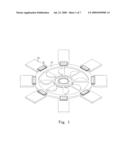
[0025]FIG. 1 is a schematic view showing a first preferred embodiment of a micro blade applied to a micro fan in the present invention;
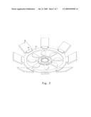
[0026]FIG. 2 is a schematic view showing the implementation for the first preferred embodiment of a micro blade applied to the micro fan in the present invention;
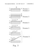
[0027]FIG. 3 is a schematic view showing steps of manufacturing processes of the present invention;
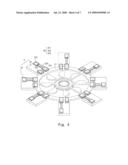
[0028]FIG. 4 is a schematic view showing a second preferred embodiment of a micro blade applied to a micro fan in the present invention;
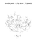
[0029]FIG. 5 is a schematic view showing the implementation for the second preferred embodiment of a micro blade applied to a micro fan in the present invention;
[0030]FIG. 6 is a schematic view showing a third preferred embodiment of a micro blade applied to a micro fan in the present invention; and
[0031]FIG. 7 is a schematic view showing the implementation for the third preferred embodiment of a micro blade applied to a micro fan in the present invention.
DETAILED DESCRIPTION OF THE PREFERRED EMBODIMENT
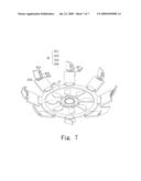
[0032]Please refer to FIG. 1 and FIG. 2. The present invention provides a first type of self-assembly micro blade to achieve a micro blade structure having movable parts. The self-assembly micro blade includes at least a movable part 21 of a microstructure, and at least an elastic joint 31 provided between the movable part 21 and an outer ring 11 of a micro motor. The elastic joint that is a photosensing ployimide film is heated to contract and generate surface tension after performing a reflow process in a high-temperature oven, so as to lift up the movable part of the microstructure and make the microstructure have a movable part for elevation while performing self assembly.
[0033]Please refer to FIG. 3. The present invention includes manufacturing processes of:
[0034](1) using plasma enhanced chemical vapor deposition method to deposit a phosphosilicate glass (PSG) on a silicon substrate 60 to serve as a low-stress sacrifice layer 70, and further using low pressure chemical vapor deposition (LPCVD) to deposit poly-silicon on the low-stress sacrifice layer as a main structure layer 80.
[0035](2) performing a first photolithography process to etch the main structure layer 80 with an inductive couple plasma (ICP) etching machine so as to etch the main structure layer 80 for defining an overall profile of the microstructure.
[0036](3) using a spin coater to coat a photosensing polyimide film 50 on the main structure layer 80 and an outer ring 11 of a BDA micro motor;
[0037](4) performing a second photolithography process to define a form of an elastic joint 31;
[0038](5) submerging the microstructure in a buffered oxide etch (BOE) solution to perform wet etch and etch and release a predetermined portion of the low-stress sacrifice layer 70; and
[0039](6) using a high-temperature oven to perform a reflow process so as to make the elastic joint 31 in molten state at high temperature and heating the elastic joint 31 to generate thermal contraction and deformation so as to lift up a predetermined portion of the main structure layer 80.
[0040]Please refer to FIG. 4 and FIG. 5. The present invention provides a second type of self-assembly micro blade to achieve a micro blade structure with curved movable parts. The self-assembly micro blade includes: at least a movable part 21 of a microstructure; at least an elastic joint 31 provided between the movable part 21 and an outer ring 11 of a micro motor; and an elastic link 315 provided on each movable part 21.
[0041]The elastic joint 31 and the elastic link 315 are composed of a photosensing polyimide film. Surface tension is generated by each elastic joint 31 and elastic link 315 through a reflow process to bend and lift up the movable part 21 of the microstructure.
[0042]The design that elastic joint and elastic link are provided between each movable part 21 and the outer ring 11 of the micro motor lies in that a first elastic joint 311 is defined on one side of each movable part 21, a second elastic joint 312 is defined on another side of each movable part 21, an elastic link 315 is defined above the first elastic joint 311 of each movable part 21, and a third elastic joint 313 is defined above the elastic link 315 of each movable part 21. Given the aforementioned reflow process, a micro blade with curved movable part can be achieved.
[0043]Please further refer to FIG. 5 showing a design for the second type of self-assembly micro blade. While performing a reflow process, each of the elastic joints (311, 312, 313) and an elastic link 315 are heated to contract and generate a surface tension due to thermal contraction so as to lift up the movable part 21. The first elastic joint 311, the elastic link 315 and the third elastic joint 313 are mutually hampered by surface tension arising from the thermal contraction process. As a result, a curved movable part 21 could be formulated.
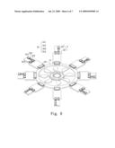
[0044]Please refer to FIG. 6 and FIG. 7. The present invention provides a third type of self-assembly micro blade to achieve a micro blade structure having multi-layer and curve moving parts. The self-assembly micro blade includes at least a first movable part 22 and a second movable part 23 of a microstructure; and an elastic joint 31 provided between the first movable part 22 and an outer ring 11 of a micro motor and between the first movable part 22 and the second movable part 23 respectively. The elastic joint 31 and the elastic link 315 are composed of a photosensing polyimide film. Surface tension is generated by each elastic joint 31 and the elastic link 315 through a reflow process to bend the movable part of the microstructure in a multi-layer and curved manner and lift it up.
[0045]The design that elastic joint and elastic link are provided between each movable part 21 and the outer ring 11 of the micro motor lies in that a first elastic joint 311 is defined on the first movable part 22, a second elastic joint 312 is defined on one side of the second movable part 23, an elastic link is defined above the second elastic joint 312 of the second movable part 23, and a fourth elastic joint 314 is defined on the elastic link 315 of the second movable part 23. Given the above-mentioned reflow process, a multi-layer and curved micro blade could be achieved.
[0046]To sum up, a comparison between the present invention and lead tin alloy ball is made as a reference to advantageous and disadvantageous characteristics thereof:
[0047]The present invention has no phenomenon of lead pollution.
[0048]The present invention won't need to evaporate a layer of gold pad additionally as a connection interface, and thus the manufacturing process thereof is simpler and the cost thereof is lower.
[0049]The present invention performs alignment with extremely high accuracy by using photolithography. Therefore, the accuracy of the micro blade of the present invention is better.
[0050]The present invention could be fully automatic in operation.
[0051]The micro blade lifted up by the design of a plurality of elastic joints and elastic links in the present invention has multi-layer and curved movable parts.
[0052]The miniaturized size of the present invention is not subject to any limitation.
[0053]Furthermore, a comparison between the present invention and the one using photoresist as elastic joint is made as a reference to advantageous and disadvantageous characteristics thereof:
[0054]Although photosensing polyimide film and photoresist are both polymer, photosensing polyimide film could withstand organic solution better since its surface tension is larger than that of photoresist. Consequently, the present invention has no doubt that elastic joint will be dissolved and destructed by Isopropyl alcohol (IPA).
[0055]As photosensing polyimode film can resist organic solution, a wet etch process having relatively lower cost could be applied, and thus the cost of the present invention is relatively lower.
[0056]The present invention is a micro blade that could completely solve many drawbacks resulting from the self assembly of a conventional micro blade, could be adopted to the development technique of a self-assembly micro fan and could break through the technical barrier of a conventional micro fan by using the foregoing description and design, so as to achieve the object of a micro blade with curved and multi-layer movable part, increasing flow rate and control, and improved flow length. From the above-mentioned characteristics those features not only have a novelty among similar products and a progressiveness but also have an industry utility.
[0057]While the invention has been described in terms of what is presently considered to be the most practical and preferred embodiments, it is to be understood that the invention needs not be limited to the disclosed embodiments. On the contrary, it is intended to cover various modifications and similar arrangements included within the spirit and scope of the appended claims, which are to be accorded with the broadest interpretation so as to encompass all such modifications and similar structures.
Claims:
1. A self-assembly micro blade, comprising:at least a movable part of a
microstructure;at least an elastic joint provided between the movable
part and an outer ring of a micro motor, and generating surface tension
to lift up the movable part of the microstructure by using a reflow
process.
2. The self-assembly micro blade as set forth in claim 1, wherein the elastic joint is a photosensing polyimide film.
3. The self-assembly micro blade as set forth in claim 1, wherein a method for manufacturing the self-assembly micro blade comprises processes of:(1) depositing a low-stress sacrifice layer on a silicon substrate and depositing a main structure layer on the low-stress sacrifice layer;(2) defining the main structure layer to etch out an overall profile of the microstructure;(3) coating a photosensing polyimide film on the main structure layer and an outer ring of the micro motor;(4) defining the polyimide film to etch out a form of an elastic joint;(5) performing wet etch to etch and release a preset portion of the low-stress sacrifice layer; and(6) performing a reflow process to heat up the elastic joint to result in thermal contraction and lifting up a preset portion of the main structure layer.
4. The self-assembly micro blade as set forth in claim 3, wherein the low-stress sacrifice layer is a phosphosilicate glass (PSG).
5. The self-assembly micro blade as set forth in claim 3, wherein the main structure layer is a polysilicon.
6. A self-assembly micro blade, comprising:at least a movable part of a microstructure; andat least an elastic joint provided between the movable part and an outer ring of a micro motor; andan elastic link provided on each movable part, so that surface tension is generated by each of the elastic joint and the elastic link through a reflow process and the movable part of the microstructure is lifted up and bent in form of curved surface;
7. The self-assembly micro blade as set forth in claim 6, wherein the elastic joint is a photosensing polyimide film.
8. The self-assembly micro blade as set forth in claim 6, wherein a first elastic joint is defined on a first side of the movable part.
9. The self-assembly micro blade as set forth in claim 6, wherein a second elastic joint is defined on a second side of the movable part.
10. The self-assembly micro blade as set forth in claim 6, wherein an elastic link is defined above the first elastic joint on each of the movable part.
11. The self-assembly micro blade as set forth in claim 6, wherein a third elastic joint is defined above the elastic link on the movable part.
12. The self-assembly micro blade as set forth in claim 6, wherein the elastic link is a photosensing polyimide film.
13. A self-assembly micro blade, comprising:at least a first movable part and a second movable part of a microstructure; andat least an elastic joint provided between the first movable part and an outer ring of a micro motor and between the first movable part and the second movable part respectively; andan elastic link is provided on each second movable part, so that surface tension is generated by each of the elastic joint and the elastic link through a reflow process and the movable part of the microstructure is lifted up and bent in form of multiple layers and curved plane.
14. The self-assembly micro blade as set forth in claim 13, wherein the elastic joint is a photosensing polyimide film.
15. The self-assembly micro blade as set forth in claim 13, wherein a first elastic joint is defined on each of the first movable part.
16. The self-assembly micro blade as set forth in claim 13, wherein a second elastic joint is defined on a first side of each of the second movable part.
17. The self-assembly micro blade as set forth in claim 13, wherein a third elastic joint is defined on a second side of each of the second movable part.
18. The self-assembly micro blade as set forth in claim 13, wherein an elastic link is defined above the second elastic joint of each of the second movable part.
19. The self-assembly micro blade as set forth in claim 13, wherein a fourth elastic joint is defined above the elastic link of each of the second movable part.
20. The self-assembly micro blade as set forth in claim 13, wherein the elastic link is a photosensing polyimide film.
Description:
FIELD OF THE INVENTION
[0001]The present invention relates to a self-assembly micro blade for micro fan, which is characterized by providing additional flow rate and control and improvement of flow length so as to solve the drawbacks of conventional skill.
BACKGROUND OF THE INVENTION
[0002]Research and application of miniaturization technology is one of two major trends of modern science. In particular, self-assembly technique is a mainstream approach for assembling microstructure in microworld in recent years.
[0003]As far as a micro fan manufactured by micro electromechanical systems (MEMS) technology is concerned, a scratch drive actuator (SDA) and a micro blade structure of the micro fan could only be built by virtue of self-assembly technique and multi-user MEMS processes (MUMPs).
[0004]The so-called self-assembly technique means that a microstructure mechanism self-positions after completing the final release process. The current self-assembly technique has the following three types of:
[0005]using the release of residual stress in manufacturing process to result in deformation enabling microstructure to displace, e.g. 3D micro optical switch developed by Lucent Technologies;
[0006]oscillating microstructure to a predetermined position by using supersonic wave to generate surface wave; and
[0007]first using solder ball, photoresist or other polymer to produce an elastic joint on a micro hinge, then making the elastic joint in molten state at high temperature through a reflow process, and generating surface tension capable of pulling up the microstructure.
[0008]Whereas, the aforementioned first type and second type of self-assembly techniques are only applicable to the microstructure in a static occasion or at a stationary position, making them not only inappropriate for manufacturing a component with displacing motion but also inappropriate for manufacturing a micro fan with rotary motion.
[0009]Furthermore, speaking of the third type of self-assembly technique, there are a lot of materials for making the elastic joint. However, different material has its respective advantageous and disadvantageous characteristics. Here exemplified by lead tin alloy ball:
[0010]lead pollution: A lead tin alloy ball is a mixture of lead and tin (63Sn/37Pb); hence, both stage and environment have the phenomenon of lead pollution during reflow;
[0011]high cost: Most of microstructures are mainly constructed by poly-silicon; if a lead tin alloy ball needs to be attached thereon, a layer of gold pad shall be coated on the surface of poly-silicon to serve as a connection interface between lead tin alloy balls. Such additional step will result in difficulty while manufacturing and cost rise.
[0012]poor accuracy: While calculating elevation angle or displacement value of a microstructure, the ball size shall be accurately grasped. However, lead tin alloy ball has a volume error up to 25%, making elevation angle or displacement value hard to be accurately controlled.
[0013]manual operation: The placement of lead tin alloy ball on the gold pad still rely on manual alignment operation for the moment.
[0014]planar lifted microstructure: The microstructure lifted by elastic joints is limited to take a planar shape and fails to be curved.
[0015]miniaturization infeasibility: Current size of lead tin alloy ball is unable to be smaller than 100 μm, making the smallest size of elastic joint become relatively restrictive.
[0016]Further exemplified by using photoresist as the material of elastic joint:
[0017]Although the process for using photoresist to manufacture elastic joint is not as complicated as that for lead tin alloy ball and the cost is lower, the cantilever release of microstructure must be performed with dry or wet etch method.
[0018]Dry etch method releases the cantilever of microstructure and replaces water molecules therein with liquid CO2 to avoid stick effect of the cantilever. However, the cost of super critical CO2 dry release equipment used by the method is expensive. Thus, the cost is relatively higher.
[0019]Wet etch method won't require additional manufacturing equipment, and thus the cost is lower. After using hydrofluoric acid (HF) or buffer oxide etcher (BOE) solution to etch sacrifice layer, isopropyl alcohol (IPA) must be applied to quickly vaporize water molecules so as to release cantilever. However, IPA is characterized by dissolving photoresist. As a result, the originally manufactured elastic joint will be destructed.
[0020]In conclusion, based on multiple concerns of cost, manufacturing process, environmental protection, miniaturization, planar lifted microstructure and so on, a totally new process surely needs to be developed to solve various shortcomings arising from the elastic joint made by lead tin alloy ball or photoresist.
SUMMARY OF THE INVENTION
[0021]A primary object of the present invention is to provide a self-assembly micro blade with movable part.
[0022]The present invention pertains to a self-assembly micro blade applied to a micro fan. The micro fan combines at least one self-assembly micro blade and a motor using an actuator as the main body of the micro fan. The self-assembly micro blade includes at least a movable part of a microstructure, and at least an elastic joint provided between the movable part and an outer ring of the micro motor, composed of a polyimide film and generating surface tension by heating the elastic joint to result in thermal contraction through a reflow process so as to lift up the movable part of the microstructure in completion of the self-assembly micro blade.
[0023]A secondary object of the present invention is to provide a self-assembly micro blade providing a curved movable part so as to address increasing air flow rate and control and improved air flow length.
[0024]The present invention is applied to a self-assembly blade of a micro fan. The micro fan combines at least a self-assembly micro blade and a motor using an actuator as the main body of the micro fan. The self-assembly micro blade includes at least a movable part of a microstructure, at least an elastic joint provided between the movable part and an outer ring of the micro motor, and an elastic link provided on each movable part. The elastic joint and the elastic link are composed of a polyimide film. By using a reflow process, the elastic joint and the elastic link are heated to contract and generate surface tension to lift up the movable part of the microstructure and form a curved movable part through the elastic link in completion of the self-assembly micro blade.
BRIEF DESCRIPTION OF THE DRAWINGS
[0025]FIG. 1 is a schematic view showing a first preferred embodiment of a micro blade applied to a micro fan in the present invention;
[0026]FIG. 2 is a schematic view showing the implementation for the first preferred embodiment of a micro blade applied to the micro fan in the present invention;
[0027]FIG. 3 is a schematic view showing steps of manufacturing processes of the present invention;
[0028]FIG. 4 is a schematic view showing a second preferred embodiment of a micro blade applied to a micro fan in the present invention;
[0029]FIG. 5 is a schematic view showing the implementation for the second preferred embodiment of a micro blade applied to a micro fan in the present invention;
[0030]FIG. 6 is a schematic view showing a third preferred embodiment of a micro blade applied to a micro fan in the present invention; and
[0031]FIG. 7 is a schematic view showing the implementation for the third preferred embodiment of a micro blade applied to a micro fan in the present invention.
DETAILED DESCRIPTION OF THE PREFERRED EMBODIMENT
[0032]Please refer to FIG. 1 and FIG. 2. The present invention provides a first type of self-assembly micro blade to achieve a micro blade structure having movable parts. The self-assembly micro blade includes at least a movable part 21 of a microstructure, and at least an elastic joint 31 provided between the movable part 21 and an outer ring 11 of a micro motor. The elastic joint that is a photosensing ployimide film is heated to contract and generate surface tension after performing a reflow process in a high-temperature oven, so as to lift up the movable part of the microstructure and make the microstructure have a movable part for elevation while performing self assembly.
[0033]Please refer to FIG. 3. The present invention includes manufacturing processes of:
[0034](1) using plasma enhanced chemical vapor deposition method to deposit a phosphosilicate glass (PSG) on a silicon substrate 60 to serve as a low-stress sacrifice layer 70, and further using low pressure chemical vapor deposition (LPCVD) to deposit poly-silicon on the low-stress sacrifice layer as a main structure layer 80.
[0035](2) performing a first photolithography process to etch the main structure layer 80 with an inductive couple plasma (ICP) etching machine so as to etch the main structure layer 80 for defining an overall profile of the microstructure.
[0036](3) using a spin coater to coat a photosensing polyimide film 50 on the main structure layer 80 and an outer ring 11 of a BDA micro motor;
[0037](4) performing a second photolithography process to define a form of an elastic joint 31;
[0038](5) submerging the microstructure in a buffered oxide etch (BOE) solution to perform wet etch and etch and release a predetermined portion of the low-stress sacrifice layer 70; and
[0039](6) using a high-temperature oven to perform a reflow process so as to make the elastic joint 31 in molten state at high temperature and heating the elastic joint 31 to generate thermal contraction and deformation so as to lift up a predetermined portion of the main structure layer 80.
[0040]Please refer to FIG. 4 and FIG. 5. The present invention provides a second type of self-assembly micro blade to achieve a micro blade structure with curved movable parts. The self-assembly micro blade includes: at least a movable part 21 of a microstructure; at least an elastic joint 31 provided between the movable part 21 and an outer ring 11 of a micro motor; and an elastic link 315 provided on each movable part 21.
[0041]The elastic joint 31 and the elastic link 315 are composed of a photosensing polyimide film. Surface tension is generated by each elastic joint 31 and elastic link 315 through a reflow process to bend and lift up the movable part 21 of the microstructure.
[0042]The design that elastic joint and elastic link are provided between each movable part 21 and the outer ring 11 of the micro motor lies in that a first elastic joint 311 is defined on one side of each movable part 21, a second elastic joint 312 is defined on another side of each movable part 21, an elastic link 315 is defined above the first elastic joint 311 of each movable part 21, and a third elastic joint 313 is defined above the elastic link 315 of each movable part 21. Given the aforementioned reflow process, a micro blade with curved movable part can be achieved.
[0043]Please further refer to FIG. 5 showing a design for the second type of self-assembly micro blade. While performing a reflow process, each of the elastic joints (311, 312, 313) and an elastic link 315 are heated to contract and generate a surface tension due to thermal contraction so as to lift up the movable part 21. The first elastic joint 311, the elastic link 315 and the third elastic joint 313 are mutually hampered by surface tension arising from the thermal contraction process. As a result, a curved movable part 21 could be formulated.
[0044]Please refer to FIG. 6 and FIG. 7. The present invention provides a third type of self-assembly micro blade to achieve a micro blade structure having multi-layer and curve moving parts. The self-assembly micro blade includes at least a first movable part 22 and a second movable part 23 of a microstructure; and an elastic joint 31 provided between the first movable part 22 and an outer ring 11 of a micro motor and between the first movable part 22 and the second movable part 23 respectively. The elastic joint 31 and the elastic link 315 are composed of a photosensing polyimide film. Surface tension is generated by each elastic joint 31 and the elastic link 315 through a reflow process to bend the movable part of the microstructure in a multi-layer and curved manner and lift it up.
[0045]The design that elastic joint and elastic link are provided between each movable part 21 and the outer ring 11 of the micro motor lies in that a first elastic joint 311 is defined on the first movable part 22, a second elastic joint 312 is defined on one side of the second movable part 23, an elastic link is defined above the second elastic joint 312 of the second movable part 23, and a fourth elastic joint 314 is defined on the elastic link 315 of the second movable part 23. Given the above-mentioned reflow process, a multi-layer and curved micro blade could be achieved.
[0046]To sum up, a comparison between the present invention and lead tin alloy ball is made as a reference to advantageous and disadvantageous characteristics thereof:
[0047]The present invention has no phenomenon of lead pollution.
[0048]The present invention won't need to evaporate a layer of gold pad additionally as a connection interface, and thus the manufacturing process thereof is simpler and the cost thereof is lower.
[0049]The present invention performs alignment with extremely high accuracy by using photolithography. Therefore, the accuracy of the micro blade of the present invention is better.
[0050]The present invention could be fully automatic in operation.
[0051]The micro blade lifted up by the design of a plurality of elastic joints and elastic links in the present invention has multi-layer and curved movable parts.
[0052]The miniaturized size of the present invention is not subject to any limitation.
[0053]Furthermore, a comparison between the present invention and the one using photoresist as elastic joint is made as a reference to advantageous and disadvantageous characteristics thereof:
[0054]Although photosensing polyimide film and photoresist are both polymer, photosensing polyimide film could withstand organic solution better since its surface tension is larger than that of photoresist. Consequently, the present invention has no doubt that elastic joint will be dissolved and destructed by Isopropyl alcohol (IPA).
[0055]As photosensing polyimode film can resist organic solution, a wet etch process having relatively lower cost could be applied, and thus the cost of the present invention is relatively lower.
[0056]The present invention is a micro blade that could completely solve many drawbacks resulting from the self assembly of a conventional micro blade, could be adopted to the development technique of a self-assembly micro fan and could break through the technical barrier of a conventional micro fan by using the foregoing description and design, so as to achieve the object of a micro blade with curved and multi-layer movable part, increasing flow rate and control, and improved flow length. From the above-mentioned characteristics those features not only have a novelty among similar products and a progressiveness but also have an industry utility.
[0057]While the invention has been described in terms of what is presently considered to be the most practical and preferred embodiments, it is to be understood that the invention needs not be limited to the disclosed embodiments. On the contrary, it is intended to cover various modifications and similar arrangements included within the spirit and scope of the appended claims, which are to be accorded with the broadest interpretation so as to encompass all such modifications and similar structures.
User Contributions:
Comment about this patent or add new information about this topic:
Images included with this patent application:
 |  |
 |  |
 |  |
 |  |
| Similar patent applications: | |
| Date | Title |
|---|---|
| 2009-08-13 | Self-assembly micro fan |
| 2013-08-22 | Hub assembly with centrifugal and radial bearings |
| 2008-11-27 | Stiff-in-plane gimbaled tiltrotor hub |
| 2011-06-16 | Thermoplastic rotor blade |
| 2013-07-11 | Turbine nozzle assembly methods |
| New patent applications in this class: | |
| Date | Title |
|---|---|
| 2018-01-25 | Wheel disk assembly having simplified sealing-plate mounting |
| 2018-01-25 | Rotor with a locking plate for securing an antirotation lock against unscrewing |
| 2016-09-01 | Fan rotor with integrated platform attachment |
| 2016-07-14 | Turbine wheel with clamped blade attachment |
| 2016-07-14 | Turbine wheel with clamped blade attachment |
| New patent applications from these inventors: | |
| Date | Title |
|---|---|
| 2018-06-07 | Silicon steel plate used to form a stator of a motor |
| 2017-09-14 | Illumination device and ventilator with light |
| 2016-04-14 | Inner-rotor motor |
| 2016-03-24 | Air exchange device capable of adjusting temperature difference |
| 2016-03-03 | External rotor motor |
| Top Inventors for class "Fluid reaction surfaces (i.e., impellers)" | |
| Rank | Inventor's name |
|---|---|
| 1 | Frank B. Stamps |
| 2 | Ching-Pang Lee |
| 3 | Gabriel L. Suciu |
| 4 | Stefan Herr |
| 5 | Tracy A. Propheter-Hinckley |