Patent application title: Curtain airbag
Inventors:
Paul Maria-Antonius Slaats (Ann Arbor, MI, US)
Pongdet Paul Wipasuramonton (Rochester, MI, US)
Pongdet Paul Wipasuramonton (Rochester, MI, US)
Mark Andrew Steinbach (Clawson, MI, US)
Mark Andrew Steinbach (Clawson, MI, US)
Richard Wiik (Fortgratiot, MI, US)
IPC8 Class: AB60R21213FI
USPC Class:
2807302
Class name: Inflatable passenger restraint or confinement (e.g., air bag) or attachment inflated confinement specially positioned relative to occupant or conforming to the body shape of occupant mounted in vehicle and positioned laterally of occupant
Publication date: 2009-07-23
Patent application number: 20090184499
e airbag is configured to extend longitudinally
along a side of a vehicle and includes a first section configured to
inflate in a longitudinal and vertical direction, a second section
coupled to the first section and configured to inflate in a longitudinal
and vertical direction, an inlet for receiving inflation gas from an
inflator, tabs positioned at the top of the airbag for attaching the
airbag to a ceiling of the vehicle and chambers positioned between the
tabs along the top of the airbag, wherein the chambers stabilize the
airbag during deployment.Claims:
1. An airbag configured to extend longitudinally along a side of a vehicle
comprising:a first section configured to inflate in a longitudinal and
vertical direction;a second section coupled to the first section and
configured to inflate in a longitudinal and vertical direction;an inlet
for receiving inflation gas from an inflator;tabs positioned at the top
of the airbag for attaching the airbag to a roof-rail or vehicle side
structure of the vehicle; andchambers positioned between the tabs along
the top of the airbag, wherein the chambers stabilize the airbag during
deployment.
2. An airbag as claimed in claim 1, wherein the first section and second section have multiple vertical chambers.
3. An airbag as claimed in claim 1, wherein the first section and second section are coupled such that air may flow between the first section and the second section.
4. An airbag as claimed in claim 1, wherein the inlet is positioned at the top of the airbag between the first section and second section.
5. An airbag as claimed in claim 1, wherein the tabs are elongated such that when the airbag is deployed the bottom of the airbag is positioned below a beltline of the vehicle.
6. A vehicle, comprising:an airbag configured to extend longitudinally along a side of a vehicle including:a first section configured to extend in a longitudinal and vertical direction;a second section coupled to the first section and configured to extend in a longitudinal and vertical direction;an inlet for receiving inflation gas from an inflator;tabs positioned at the top of the airbag for attaching the airbag to a ceiling of the vehicle; andchambers positioned between the tabs along the top of the airbag, wherein the chambers stabilize the airbag during deployment.
7. A vehicle as claimed in claim 6, wherein the first section and second section have multiple vertical chambers.
8. A vehicle as claimed in claim 6, wherein the first section and second section are coupled such that air may flow between the first section and the second section.
9. A vehicle as claimed in claim 6, wherein the inlet is positioned at the top of the airbag between the first section and second section.
10. A vehicle as claimed in claim 6, wherein the tabs are elongated such that when the airbag is deployed the bottom of the airbag is positioned below a beltline of the vehicle.Description:
BACKGROUND
[0001]The present invention relates generally to the field of airbags. More specifically, the invention relates to curtain type airbags configured to deploy along the side of the passenger cabin of vehicle.
[0002]Curtain or roof rail airbags are typically deployed from behind a trim element in a vehicle. The airbag deploys between the sheet metal of the vehicle and the trim element and then out along vehicle side windows into the vehicle cabin to protect an occupant or occupants. Conventional curtain airbags are provided with inflated gas chambers for occupant head cushioning. Most of the airbags form a continuous gas channel in the upper area of the airbag close to the roof rail area. When the airbag is deployed these chambers break through the vehicle trim first.
[0003]Government agencies have indicated that certain requirements for mitigating the ejection of an occupant from a vehicle will be mandated in the future. Curtain airbag technology will become important in these ejection mitigation efforts. To limit the size of a curtain airbag inflator, it is desirable for the volume of the cushion airbag to be used as efficiently as possible while extending throughout the height of the side windows of the vehicle to insure occupant safety.
SUMMARY
[0004]According to one embodiment, an airbag is configured to extend longitudinally along a side of a vehicle and includes a first section configured to inflate in a longitudinal and vertical direction, a second section coupled to the first section and configured to inflate in a longitudinal and vertical direction, an inlet for receiving inflation gas from an inflator, tabs positioned at the top of the airbag for attaching the airbag to a roof-rail of the vehicle and chambers positioned between the tabs along the top of the airbag, wherein the chambers stabilize the inflated airbag during deployment.
[0005]It is to be understood that both the foregoing general description and the following detailed description are exemplary and explanatory only, and are not restrictive of the invention as claimed.
BRIEF DESCRIPTION OF THE DRAWINGS
[0006]Features, aspects and advantages of the present invention will become apparent from the following description, appended claims, and the accompanying exemplary embodiments shown in the drawings, which are briefly described below.
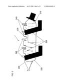
[0007]FIG. 1 is a sectional view of a conventional curtain airbag.
[0008]FIG. 2 is a sectional profile view of a vehicle having a curtain airbag according to one embodiment.
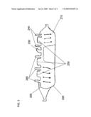
[0009]FIG. 3 is a sectional view of a curtain airbag according to one embodiment.
DETAILED DESCRIPTION
[0010]Embodiments of the present invention will be described below with reference to the accompanying drawings. It should be understood that the following description is intended to describe exemplary embodiments of the invention, and not to limit the invention.
[0011]Referring to FIG. 1, airbag 100 may include a first section 110 and a second section 120. The first section 110 may be integrally formed with the second section 120, such that air may flow (in fluid communication) between the two sections 110, 120. Alternatively, the first section 110 may be a separate section that is connected (directly or indirectly) to the second section 120. The first section 110 may be rolled, folded or unfolded. The second section 120 may be folded or rolled in any appropriate manner for a roof rail airbag. In the embodiment shown in FIG. 1, both the first 110 and second section 120 are configured to inflate and deploy downward between a headliner trim and a roof-rail into a vehicle cabin area along the side windows in front of trim components. Airbag 100 may be constructed from materials known in the art.
[0012]Still referring to FIG. 1, the airbag 100 is shown to include an inflation inlet shown as inlet 130. Inlet 130 is used to connect an inflator (not shown) to airbag 100. As shown in FIG. 1, inlet 130 is positioned between first section 110 and second section 120. When airbag 100 is deployed, this position of inlet 130 allows both sections 110, 120 to be quickly and simultaneously filled. In an alternative embodiment, inlet 130 may be located in first section 110, or may be located in second section 120. Alternatively, separation gas introduction ports may be provided so that inflation gas is provided to the first and second inflatable sections of the airbag in a controlled manner.
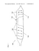
[0013]Airbag 100 is shown in FIG. 1 to include multiple vertical chambers in a first section 110 and multiple vertical chambers in a second section 120. The airbag 100 may be configured in multiple shapes and sizes. Airbag 100 may comprise any number, shape and size of horizontal and/or vertical chambers. Airbag 100 also includes multiple attachment points 140. Attachment points 140 may be positioned at any point along the top of airbag 100 and may be constructed from materials known in the art.
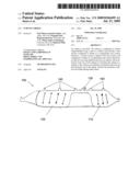
[0014]FIGS. 2 and 3 show a sectional profile view of a vehicle 1 having an airbag 200 and an airbag 200 according to one embodiment. The airbag 200 may include a first section 210 and a second section 220. The first section 210 may be integrally formed with the second section 220, such that air may flow (in fluid communication) between the two sections 210, 220. Alternatively, the first section 210 may be a separate section that is connected (directly or indirectly) to the second section 220. The first section 210 may be rolled, folded or unfolded. The second section 220 may be folded or rolled in any appropriate manner for a roof rail airbag. In the embodiment shown in FIG. 3, both the first 210 and second section 220 are configured to inflate and deploy downward between a headliner trim and a roof-rail into a vehicle cabin area in front of trim components. Airbag 200 may be constructed from materials known in the art.
[0015]Still referring to FIG. 3, the airbag 200 is shown to include an inflation inlet shown as inlet 230. Inlet 230 is used to connect an inflator (not shown) to airbag 200. As shown in FIG. 1, inlet 230 is positioned between first section 210 and second section 220. When airbag 200 is deployed, this position of inlet 230 allows both sections 210, 220 to be quickly and simultaneously filled. In an alternative embodiment, inlet 230 may be located in first section 210, or may be located in second section 220. Alternatively, separation gas introduction ports may be provided so that inflation gas is provided to the first and second inflatable sections of the airbag in a controlled manner.
[0016]Airbag 200 is shown in FIG. 3 to include multiple vertical chambers in the first section 210 and multiple vertical chambers in the second section 220. The airbag 200 may be configured in multiple shapes and sizes. Airbag 200 may comprise any number, shape and size of horizontal and/or vertical chambers. Airbag 200 also includes multiple elongated attachment tabs 240. The elongated attachment tabs 240 may be positioned at any point along the top of airbag 200 and may be constructed from materials known in the art. The elongated attachment tabs 240 are longer than the conventional attachment points 140 shown in FIG. 1. For example, the attachment tabs 240 may extend, but not limited to, as much as 2.5 inches longer than conventional tabs from their attachment point. The elongated attachment points 240 insure that the bottom of the airbag overlaps the beltline of the vehicle 1.
[0017]In addition, the airbag 200 includes upper chambers 250. The upper chambers 250 are positioned between the elongated attachment tabs 240 along the upper length of the airbag 200. Upon deployment, the upper chambers 250 act to stabilize the airbag 200 by pushing against the roof-rail surface to insure that the airbag 200 stays deployed at its full length along the height of the vehicle. The inflated upper chambers also help minimize vertical oscillation motions. The upper chambers 250 may also act as a regular cushioning chamber. Further, by positioning the attachment tabs 240 along the length of the airbag in conjunction with the upper chambers 250, the overall volume of the airbag can be kept small. In other words, the inflated cushion would have to cover the full height from the roof-rail down to at least the window sill. With the mounting tabs and upper chambers, the tabs can be lengthened; and the upper chambers will stabilize the airbag deployment and give the occupant(s) protection. Thus the inflated cushion can be minimized. Therefore, the inflator output can also be kept small. It is noted that the lengthened tabs essentially lower the upper gas distribution channel (i.e. the straight channel just below the upper chambers and the tabs in FIG. 3). Since the upper channel remains straight, the gas distribution is relatively the same.
[0018]The foregoing description of a preferred embodiment of the invention has been presented for purposes of illustration and description. It is not intended to be exhaustive or to limit the invention to the precise form disclosed, and modifications and variations are possible in light of the above teaching or may be acquired from practice of the invention. The embodiment was chosen and described in order to explain the principles of the invention and as a practical application to enable one skilled in the art to utilize the invention in various embodiments and with various modification are suited to the particular use contemplated. It is intended that the scope of the invention be defined by the claims appended hereto and their equivalents.
Claims:
1. An airbag configured to extend longitudinally along a side of a vehicle
comprising:a first section configured to inflate in a longitudinal and
vertical direction;a second section coupled to the first section and
configured to inflate in a longitudinal and vertical direction;an inlet
for receiving inflation gas from an inflator;tabs positioned at the top
of the airbag for attaching the airbag to a roof-rail or vehicle side
structure of the vehicle; andchambers positioned between the tabs along
the top of the airbag, wherein the chambers stabilize the airbag during
deployment.
2. An airbag as claimed in claim 1, wherein the first section and second section have multiple vertical chambers.
3. An airbag as claimed in claim 1, wherein the first section and second section are coupled such that air may flow between the first section and the second section.
4. An airbag as claimed in claim 1, wherein the inlet is positioned at the top of the airbag between the first section and second section.
5. An airbag as claimed in claim 1, wherein the tabs are elongated such that when the airbag is deployed the bottom of the airbag is positioned below a beltline of the vehicle.
6. A vehicle, comprising:an airbag configured to extend longitudinally along a side of a vehicle including:a first section configured to extend in a longitudinal and vertical direction;a second section coupled to the first section and configured to extend in a longitudinal and vertical direction;an inlet for receiving inflation gas from an inflator;tabs positioned at the top of the airbag for attaching the airbag to a ceiling of the vehicle; andchambers positioned between the tabs along the top of the airbag, wherein the chambers stabilize the airbag during deployment.
7. A vehicle as claimed in claim 6, wherein the first section and second section have multiple vertical chambers.
8. A vehicle as claimed in claim 6, wherein the first section and second section are coupled such that air may flow between the first section and the second section.
9. A vehicle as claimed in claim 6, wherein the inlet is positioned at the top of the airbag between the first section and second section.
10. A vehicle as claimed in claim 6, wherein the tabs are elongated such that when the airbag is deployed the bottom of the airbag is positioned below a beltline of the vehicle.
Description:
BACKGROUND
[0001]The present invention relates generally to the field of airbags. More specifically, the invention relates to curtain type airbags configured to deploy along the side of the passenger cabin of vehicle.
[0002]Curtain or roof rail airbags are typically deployed from behind a trim element in a vehicle. The airbag deploys between the sheet metal of the vehicle and the trim element and then out along vehicle side windows into the vehicle cabin to protect an occupant or occupants. Conventional curtain airbags are provided with inflated gas chambers for occupant head cushioning. Most of the airbags form a continuous gas channel in the upper area of the airbag close to the roof rail area. When the airbag is deployed these chambers break through the vehicle trim first.
[0003]Government agencies have indicated that certain requirements for mitigating the ejection of an occupant from a vehicle will be mandated in the future. Curtain airbag technology will become important in these ejection mitigation efforts. To limit the size of a curtain airbag inflator, it is desirable for the volume of the cushion airbag to be used as efficiently as possible while extending throughout the height of the side windows of the vehicle to insure occupant safety.
SUMMARY
[0004]According to one embodiment, an airbag is configured to extend longitudinally along a side of a vehicle and includes a first section configured to inflate in a longitudinal and vertical direction, a second section coupled to the first section and configured to inflate in a longitudinal and vertical direction, an inlet for receiving inflation gas from an inflator, tabs positioned at the top of the airbag for attaching the airbag to a roof-rail of the vehicle and chambers positioned between the tabs along the top of the airbag, wherein the chambers stabilize the inflated airbag during deployment.
[0005]It is to be understood that both the foregoing general description and the following detailed description are exemplary and explanatory only, and are not restrictive of the invention as claimed.
BRIEF DESCRIPTION OF THE DRAWINGS
[0006]Features, aspects and advantages of the present invention will become apparent from the following description, appended claims, and the accompanying exemplary embodiments shown in the drawings, which are briefly described below.
[0007]FIG. 1 is a sectional view of a conventional curtain airbag.
[0008]FIG. 2 is a sectional profile view of a vehicle having a curtain airbag according to one embodiment.
[0009]FIG. 3 is a sectional view of a curtain airbag according to one embodiment.
DETAILED DESCRIPTION
[0010]Embodiments of the present invention will be described below with reference to the accompanying drawings. It should be understood that the following description is intended to describe exemplary embodiments of the invention, and not to limit the invention.
[0011]Referring to FIG. 1, airbag 100 may include a first section 110 and a second section 120. The first section 110 may be integrally formed with the second section 120, such that air may flow (in fluid communication) between the two sections 110, 120. Alternatively, the first section 110 may be a separate section that is connected (directly or indirectly) to the second section 120. The first section 110 may be rolled, folded or unfolded. The second section 120 may be folded or rolled in any appropriate manner for a roof rail airbag. In the embodiment shown in FIG. 1, both the first 110 and second section 120 are configured to inflate and deploy downward between a headliner trim and a roof-rail into a vehicle cabin area along the side windows in front of trim components. Airbag 100 may be constructed from materials known in the art.
[0012]Still referring to FIG. 1, the airbag 100 is shown to include an inflation inlet shown as inlet 130. Inlet 130 is used to connect an inflator (not shown) to airbag 100. As shown in FIG. 1, inlet 130 is positioned between first section 110 and second section 120. When airbag 100 is deployed, this position of inlet 130 allows both sections 110, 120 to be quickly and simultaneously filled. In an alternative embodiment, inlet 130 may be located in first section 110, or may be located in second section 120. Alternatively, separation gas introduction ports may be provided so that inflation gas is provided to the first and second inflatable sections of the airbag in a controlled manner.
[0013]Airbag 100 is shown in FIG. 1 to include multiple vertical chambers in a first section 110 and multiple vertical chambers in a second section 120. The airbag 100 may be configured in multiple shapes and sizes. Airbag 100 may comprise any number, shape and size of horizontal and/or vertical chambers. Airbag 100 also includes multiple attachment points 140. Attachment points 140 may be positioned at any point along the top of airbag 100 and may be constructed from materials known in the art.
[0014]FIGS. 2 and 3 show a sectional profile view of a vehicle 1 having an airbag 200 and an airbag 200 according to one embodiment. The airbag 200 may include a first section 210 and a second section 220. The first section 210 may be integrally formed with the second section 220, such that air may flow (in fluid communication) between the two sections 210, 220. Alternatively, the first section 210 may be a separate section that is connected (directly or indirectly) to the second section 220. The first section 210 may be rolled, folded or unfolded. The second section 220 may be folded or rolled in any appropriate manner for a roof rail airbag. In the embodiment shown in FIG. 3, both the first 210 and second section 220 are configured to inflate and deploy downward between a headliner trim and a roof-rail into a vehicle cabin area in front of trim components. Airbag 200 may be constructed from materials known in the art.
[0015]Still referring to FIG. 3, the airbag 200 is shown to include an inflation inlet shown as inlet 230. Inlet 230 is used to connect an inflator (not shown) to airbag 200. As shown in FIG. 1, inlet 230 is positioned between first section 210 and second section 220. When airbag 200 is deployed, this position of inlet 230 allows both sections 210, 220 to be quickly and simultaneously filled. In an alternative embodiment, inlet 230 may be located in first section 210, or may be located in second section 220. Alternatively, separation gas introduction ports may be provided so that inflation gas is provided to the first and second inflatable sections of the airbag in a controlled manner.
[0016]Airbag 200 is shown in FIG. 3 to include multiple vertical chambers in the first section 210 and multiple vertical chambers in the second section 220. The airbag 200 may be configured in multiple shapes and sizes. Airbag 200 may comprise any number, shape and size of horizontal and/or vertical chambers. Airbag 200 also includes multiple elongated attachment tabs 240. The elongated attachment tabs 240 may be positioned at any point along the top of airbag 200 and may be constructed from materials known in the art. The elongated attachment tabs 240 are longer than the conventional attachment points 140 shown in FIG. 1. For example, the attachment tabs 240 may extend, but not limited to, as much as 2.5 inches longer than conventional tabs from their attachment point. The elongated attachment points 240 insure that the bottom of the airbag overlaps the beltline of the vehicle 1.
[0017]In addition, the airbag 200 includes upper chambers 250. The upper chambers 250 are positioned between the elongated attachment tabs 240 along the upper length of the airbag 200. Upon deployment, the upper chambers 250 act to stabilize the airbag 200 by pushing against the roof-rail surface to insure that the airbag 200 stays deployed at its full length along the height of the vehicle. The inflated upper chambers also help minimize vertical oscillation motions. The upper chambers 250 may also act as a regular cushioning chamber. Further, by positioning the attachment tabs 240 along the length of the airbag in conjunction with the upper chambers 250, the overall volume of the airbag can be kept small. In other words, the inflated cushion would have to cover the full height from the roof-rail down to at least the window sill. With the mounting tabs and upper chambers, the tabs can be lengthened; and the upper chambers will stabilize the airbag deployment and give the occupant(s) protection. Thus the inflated cushion can be minimized. Therefore, the inflator output can also be kept small. It is noted that the lengthened tabs essentially lower the upper gas distribution channel (i.e. the straight channel just below the upper chambers and the tabs in FIG. 3). Since the upper channel remains straight, the gas distribution is relatively the same.
[0018]The foregoing description of a preferred embodiment of the invention has been presented for purposes of illustration and description. It is not intended to be exhaustive or to limit the invention to the precise form disclosed, and modifications and variations are possible in light of the above teaching or may be acquired from practice of the invention. The embodiment was chosen and described in order to explain the principles of the invention and as a practical application to enable one skilled in the art to utilize the invention in various embodiments and with various modification are suited to the particular use contemplated. It is intended that the scope of the invention be defined by the claims appended hereto and their equivalents.
User Contributions:
Comment about this patent or add new information about this topic:
Images included with this patent application:
 |  |
 |  |
| Similar patent applications: | |
| Date | Title |
|---|---|
| 2008-12-18 | Curtain airbag system |
| 2009-01-01 | Curtain air bag apparatus |
| 2009-01-29 | Curtain airbag device |
| 2009-02-26 | Inflatable curtain airbags |
| 2009-03-05 | Curtain airbag |
| New patent applications in this class: | |
| Date | Title |
|---|---|
| 2019-05-16 | Vehicle side airbag device |
| 2018-01-25 | Vehicular occupant restraining device |
| 2018-01-25 | Vehicle occupant restraining system |
| 2017-08-17 | Center side airbag module |
| 2016-09-01 | Curtain airbag apparatus and method of manufacturing the same |
| New patent applications from these inventors: | |
| Date | Title |
|---|---|
| 2016-06-30 | Side impact airbag module |
| 2014-03-20 | Motor vehicles having bumper counter rotation brackets |
| 2013-11-07 | Airbag module with light weight airbag cushion |
| 2013-09-12 | Airbag device |
| Top Inventors for class "Land vehicles" | |
| Rank | Inventor's name |
|---|---|
| 1 | Osamu Fukawatase |
| 2 | Christopher P. D'Aluisio |
| 3 | Richard W. Mccoy |
| 4 | Jun Yeol Choi |
| 5 | Yusuke Fujiwara |