Patent application title: REUSABLE TEMPORARY SAFETY RAIL POST
Inventors:
Joseph Carvalho (Bradford, CA)
Jose Carvalho (Bradford, CA)
IPC8 Class: AE04H1714FI
USPC Class:
256 6514
Class name: Rail connection post to base support
Publication date: 2009-06-25
Patent application number: 20090159865
assembly for a safety fence for bordering an
elevated work area, the work area including a wall section supporting an
elevated floor section to be bordered by the safety fence, the post
assembly comprising a stanchion having upper and lower sections, the
lower section having a first upper and a second lower plate fixedly
connected thereto, the first and second plates being vertically spaced
apart by a pre-determined distance, the upper portion having one or more
brackets connected thereto for supporting horizontal safety rails which
extend between adjacent post assemblies, and a third plate connectable to
the wall section at a selected location, the third plate including means
for a torque-resistant connection to the first plate to hold the
stanchion in a vertically upright position relative to the wall section,
wherein the second plate is connectable to the wall section when the
first plate is connected to the third plate, thereby securing the
stanchion to the wall section.Claims:
1. A post assembly for a safety fence for bordering an elevated work area,
the work area including a wall section supporting an elevated floor
section to be bordered by the safety fence, said post assembly
comprising:a stanchion member having upper and lower sections, said lower
section having a first upper and a second lower plate fixedly connected
thereto, said first and second plates being vertically spaced apart by a
pre-determined distance, said upper portion having one or more brackets
connected thereto for supporting horizontal safety rails which extend
between adjacent post assemblies; anda third plate connectable to the
wall section at a selected location, said third plate including means for
a torque-resistant connection to said first plate to hold said stanchion
in a vertically upright position relative to the wall section;wherein
said second plate is connectable to the wall section when said first
plate is connected to said third plate, thereby securing said stanchion
to the wall section.
2. The assembly of claim 1 wherein said third plate is formed with a slot to slidably receive said first plate thereinto.
3. The assembly of claim 2 wherein said slot is vertically aligned so that said first plate slides vertically into said slot to connect said stanchion to said third plate and slides vertically out of said slot to disconnect said stanchion from said third plate.
4. The assembly of claim 1 wherein said third plate is connectable to the wall section by means of fasteners.
5. The assembly of claim 4 wherein said second plate is connectable to the wall section by means of fasteners.
6. The assembly of claim 5 wherein a lower edge of said second plate includes one or more vertically extending slots formed therein.
7. The assembly of claim 6 wherein said fasteners connecting said second plate to the wall section extend through said one or more vertically extending slots.
8. The assembly of claim 7 wherein said stanchion can be disconnected from the wall portion by lifting it vertically to withdraw said first plate from said slot in said third plate and to pull said second plate past said fasteners inserted through said one or more vertical slots.
9. The assembly of claim 8 wherein said third plate includes a plurality of holes preformed therein for the insertion of fasteners to connect said third plate to the wall portion.
10. The assembly of claim 1 wherein said stanchion includes a bend between said upper and lower sections so that said upper section slopes away from said elevated work area.
11. The assembly of claim 10 wherein said bend is about five degrees.
12. A method for connecting a safety fence around an elevated work surface supported by an underlying wall section, the method comprising the steps of:fixedly connecting first and second vertically spaced apart plate members to a lower section of a stanchion member;fixedly connecting a third plate member adjacent an upper edge of the wall section, the third plate member being adapted for a temporary, load bearing connection to the first plate on said stanchion;connecting said first and third plates together, whereby said second plate is automatically positioned in opposed relation to the wall section for connection thereto, said first, second and third plate members cooperating to secure said stanchion in a vertically upright position relative to the wall section to provide a torque resistant connection between the stanchion and the wall section.
13. The method of claim 12 wherein the second plate is vertically slidable into and out of slot means formed in said third plate for connecting and disconnecting the stanchion to the wall section.
14. A post assembly for a safety fence for bordering an elevated work area, the work area including wall portions supporting an elevated outwardly cantilevered floor portion to be bordered by the safety fence, the wall portion including vertical studs topped by a header and the floor portion including horizontal joists surrounded by a fascia; the post assembly comprising:a stanchion member having an upper portion and a lower end, said upper portion including one or more brackets thereon to support horizontal safety rails which extend between adjacent post assemblies; anda yoke member connected to said lower end of said stanchion, said yoke member connecting said stanchion to the header of the wall portion to be in horizontally spaced apart relation to the fascia of the floor portion.
15. The assembly of claim 14 wherein said yoke member comprises a bracket portion shaped to fit over the header of the wall portion and a plate member connected to extend horizontally outwardly from the bracket portion to pass beneath the fascia of the floor portion.
16. The assembly of claim 15 wherein said stanchion is fixedly connected adjacent an outer edge of said plate member to extend vertically upright relative to the wall portion and to be horizontally spaced apart from the fascia of the floor portion.
17. The assembly of claim 16 wherein said bracket portion is an inverted U-shape to closely fit over and engage the header of the wall portion.
18. The assembly of claim 17 wherein said bracket portion includes an upper surface and two downwardly depending side surfaces that define said inverted U-shape, the height of said side surfaces being selected to prevent separation of said bracket portion from the header when a load is applied to said stanchion.
19. The assembly of claim 18 wherein said plate member is resiliently flexible whereby outwardly acting torque applied to said stanchion causes the plate member to flex downwardly relative to said bracket portion.
20. The assembly of claim 15 wherein said plate member is reinforced against flexing when loaded.
21. The assembly of claim 20 wherein said plate member is reinforced with a stiffening rib fixedly connected thereto.Description:
FIELD OF THE INVENTION
[0001]The present invention relates to a reusable temporary safety rail post. Specifically, the present safety rail post is an apparatus for constructing safety fences for containing elevated work areas during residential or commercial construction. The post can be installed temporarily with minimal effort and is reusable on multiple construction projects.
BACKGROUND OF THE INVENTION
[0002]It is commonplace, and required by law in many jurisdictions, to construct a temporary safety fence around raised work areas. This provides fall protection for workers working above the ground. Occasionally, workers construct temporary railings made of lumber found around a typical construction site. However these temporary wooden railings lack strength, are susceptible to weathering, waste valuable lumber and are not based on a single proven design to ensure safety.
[0003]The prior art describes a number of solutions to address this problem.
[0004]U.S. Pat. No. 6,908,075 to Nichols discloses a safety rail system designed for residential housing constructions having cantilevered second stories. The Nichols safety rail is cantilevered away from the first floor walls to allow for the overhanging second story, and once the separate rail posts are linked together using rails constructed from dimensional lumber, the elevated work area is contained. However, the Nichols safety rail attaches to the first floor studs by means of wood screws in a semi-permanent manner and cannot be easily removed once the cantilevered second story floor is installed. This results in the Nichols safety rail being difficult to remove once the second story is complete and the safety rail is no longer necessary.
[0005]U.S. Pat. No. 5,314,167 to Holloman discloses a temporary rail structure designed to attach to the floor joist header of the second story. This temporary rail utilizes common lumber to construct the railings as in Nichols and attaches via a U shaped yoke that clamps tightly to the outer floor joist header. Linking multiple Holloman posts together with lumber rails of typical lumber results in a safety rail that contains the work area, however the aforementioned U shaped yoke does not allow plywood subflooring to be installed while the rail is in place. Therefore, the Holloman rail must be removed when the subflooring is installed, which typically occurs at a time when the safety rails are still required, as the second floor walls have not been completed.
[0006]U.S. Pat. No. 4,666,131 to Kettelcamp, Sr. et al. discloses an adjustable guard rail stanchion which clamps to the underside of a roofing truss. The Kettelcamp guard rail stanchion is easily installed and removed, however it is particularly designed for a roofing application and cannot be readily modified for the needs of second story work area containment.
[0007]Accordingly, there is a need for a safety rail post that is quick and easy to install and remove, reusable, strong and adaptable to different types of residential house constructions.
SUMMARY OF THE INVENTION
[0008]The present invention overcomes the deficiencies of the prior ad by providing a safety rail post that can be easily installed during construction and quickly removed after the safety rail is no longer necessary. It does so without limiting access to the work structure while providing an effective safeguard against an inadvertent fall by a worker.
[0009]The reusable temporary safety post is comprised of an upright stanchion with a bottom bracket arrangement. During use, the safety rail posts are installed on the work structure, the method of doing so varying depending on the type of construction employed, as discussed below. Once installed in place, the separate reusable safety posts can be linked together using rails consisting of typical construction lumber, which fit into angular railing brackets provided on the upright stanchions. The rails are easily secured in place using nails or wood screws inserted through a hole provided in the angular railing brackets.
[0010]In the case of a typical two story house construction, the reusable safety posts are secured to the work structure according to a first aspect of the invention. Specifically, a slotted female plate is secured near the top of the first story wall sheathing on the outside. This slotted female plate mates with an insertable male plate located near the bottom of the upright stanchion. Each post is additionally further secured to the lower wall structure by means of a lower support plate located at the bottom of the upright stanchion. Two by four safety rails may then be installed to span the gaps between adjacent posts. Removal consists of the preceding steps carried out in reverse order.
[0011]Another aspect of the present invention, which involves a reusable temporary safety rail post with a cantilevering bottom bracket, is used in applications where the structure's second story is cantilevered out from the first story. In this arrangement, the cantilevered bottom bracket is designed with an inverted U-shaped yoke that fits over the header of the first floor wall. The cantilevered design extends the reusable safety post away from first floor wall such that it does not interfere in the construction of the overhanging second story floor. The two by four rails are installed between adjacent posts in the same manner as described above. Removal is accomplished by simply removing the rails and "unhooking" the safety posts from the top of the first story wall.
BRIEF DESCRIPTION OF THE DRAWINGS
[0012]Preferred embodiments of the present invention will now be described in greater detail and will be better understood when read in conjunction with the following drawings in which:
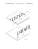
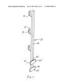
[0013]FIG. 1 is a perspective view of the reusable temporary safety rail post adapted for use in typical two story residential house construction;
[0014]FIG. 2 is an exploded view of the mating male and female plates of FIG. 1;
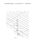
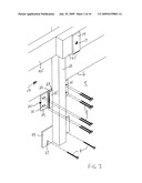
[0015]FIG. 3 is a perspective view of the safety rail post in an installed position;
[0016]FIG. 4 is a perspective view of a plurality of safety rail posts pre-installed on a wall section which is then rotated into an upright position;
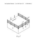
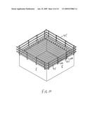
[0017]FIG. 5 is a perspective view of the safety rail posts forming a fence around a completed first story;
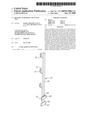
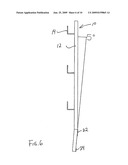
[0018]FIG. 6 is a perspective view of a modified temporary safety rail post;
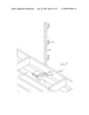
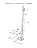
[0019]FIG. 7 is a perspective view of a reusable temporary safety rail post adapted for a two story residential house construction incorporating a cantilevered second floor;
[0020]FIG. 8 is a front perspective view of the safety rail post of FIG. 7 in an installed position;
[0021]FIG. 9 is a rear perspective view of the safety rail post shown in FIG. 8; and
[0022]FIG. 10 is a perspective view of the safety rail posts of FIG. 7 forming a fence around the cantilevered floor of a second story.
DETAILED DESCRIPTION OF THE PREFERRED EMBODIMENTS
[0023]With reference to FIG. 1, showing the safety rail post used for non-cantilevered constructions, the present invention consists of reusable temporary safety post 10 which is comprised of an upright stanchion 12, a number of angular railing brackets 14, and a bottom bracket assembly 30 which is used to connect the safety posts to the upper edge of the first story wall as will be described below. These components may be manufactured from metal, with aluminum and galvanized or stainless steel being preferred.
[0024]With reference to FIGS. 2 and 3, bottom bracket assembly 30 consists of first and second plates 22 and 24 strongly connected to stanchion 12, such as by means of permanent welds, and a bracket 20, which slidingly connects with first plate 22, and which itself is securely connected as shown in FIG. 3 to the upper edge 6 of first story wall 5.
[0025]In the case of a typical two story residential housing construction where there is no overhang of the second story floor over the first floor walls, post 10 is installed as follows. Referring to FIGS. 2 and 3, bracket 20 is fastened to wall 5 using wood screws or nails 8 inserted through pre-drilled holes 21 in the bracket's base plate 19 into the wall's exterior sheathing or the wall studs behind the sheathing. This can occur before or after the first floor wall has been erected, but preferably occurs as the completed wall structure is lying flat on the ground floor as shown in FIG. 4 for easy access.
[0026]Once bracket 20 is installed post 10 can be installed. This is achieved by sliding first plate 22 into bracket 20 previously mounted onto wall 5 As can be seen best in FIG. 2, bracket 20 includes a pair of opposed flanges 25 welded onto base plate 19 to define a slot 26 between them sized to slidingly receive plate 22. The lower ends 28 of slot 26 inside the flanges can be closed or stoppered for example by depositing a bead of excess welding material or by any other means known in the art. This controls the degree of insertion of plate 22 into slot 26. The dashed weld lines 23 indicate where first plate 22 is welded to upright stanchion 12 (not shown in FIG. 2).
[0027]Once safety post 10 is installed into bracket 20, it is then additionally secured by fastening lower support plate 24 to wall 5 using nails or wood screws 8 inserted through slots 27 formed or cut into the lower edge of plate 24. Lower support plate 24 provides enhanced stability to the entire assembly, and is located at the tower end stanchion 12 on the same side as plate 22. Once all the support posts 10 are connected, wall 5 can be rotated onto its upright position as shown in FIG. 4.
[0028]With posts 10 in place, safety rails 45, typically two by fours, can be installed with the length of the rails determined by the requirements of the particular application as shown in FIG. 5. The safety rails can be installed before or after wall 5 is rotated into its upright position, but for ease of installation, and for safety reasons, the rails are preferably installed before the wall is moved upright. Ideally, angular railing brackets 14 are sized to receive two rails placed side by side and secured by a nail or wood screw inserted through a hole 17 provided in each bracket. In one embodiment of the invention, each post 10 may have three railing brackets 14.
[0029]Removal of posts 10 is accomplished by removing rails 45 and then pulling posts 10 upwardly to disengage plate 22 from bracket 20. Plate 24 will simultaneously slide past nails or screws 8 in slots 27. Brackets 20 and fasteners 8 can be removed later or left in place to be covered by brick or siding.
[0030]Reference will now be made to FIG. 6 showing a modified safety rail post 10 wherein like numerals have been used to identify like elements. In this embodiment, stanchion 12 is formed with a small dog leg bend of about 5 degrees. The angle of the bend can be bigger or smaller as required. The bend can be formed by actually bending the stanchion by the desired amount or welding two pieces of stanchion together at the desired angle. The bend slopes the portion of the stanchion above the bend away from the work area to provide additional clearance for installation of the rim joists that surround the second story floor joists.
[0031]In one embodiment constructed by the applicant, the stanchions are 1.5'' square, plate 22 is 21/2'' wide by 3'' high, plate 24 is 6'' wide by 11/2'' to 3'' high, bracket 20 is 7'' wide by 3'' high. These pieces are preferably made from 3/16'' thick steel plate.
[0032]In another application, the present invention may be modifed for use in housing construction in which cantilevered second stories are employed. This occurs for example when a second story floor extends out past the first floor walls in order to accommodate a brick fascia on the outside of the first floor with vinyl or aluminum siding or a similar cladding on the second floor.
[0033]In this embodiment of the present invention, the reusable temporary safety post has a bottom bracket arrangement adapted to fit over the upper edge or header of the first floor wall.
[0034]Reference will now be made to FIG. 7 showing a safety post 100 modified for this particular application.
[0035]As will be seen post 100 includes a stanchion 120 and one or more rail brackets 140. The stanchion and brackets are substantially the same as described above with respect to the embodiment of FIGS. 1 to 5. In this embodiment however, plates 22 and 24 and bracket 20 are replaced by a cantilevering yoke 210.
[0036]Yoke 210 consists of a horizontal plate 215 that stanchion 120 is welded to and an inverted U-shaped bracket 220 that is sized to closely fit over the header 7 of lower wall 5 as shown most clearly in FIGS. 8 and 9. Added between stanchion 120 and bracket 220 is a stiffening rib 224 that prevents plate 215 from flexing when a load is applied to the safety rails. The stiffening rib is strongly connected to the yoke such as by welding. The use of rib 224 is but one example of a means to reinforce plate 215 against flexing. Numerous others will occur to those skilled in the art.
[0037]Installation can occur before or after the second story floor 234 is installed, but necessarily after the first floor walls have been erected. Bracket 220 is fitted over header 7 of first floor wall 5. If the second story floor is already installed, posts 100 must necessarily be installed between the second story floor joists. When installed, plate 215 and stiffening rib 224 pass beneath the fascia or rim joist 235 of second story floor 234. Plate 215 is long enough that stanchion 120 easily clears the fascia preferably by at least 2''. Since plate 215 passes beneath the fascia, it does not interfere in the installation of plywood or underlay to the upper surface of the second story floor, nor in the erection of the second story walls. Once the posts 100 are installed, safety rails 415 are installed in the same manner described above to form a fence around the second story floor as shown in FIG. 10.
[0038]As mentioned above, stiffening rib 224 prevents horizontal plate 215 from flexing when loaded. This prevents torque applied to the stanchions from inadvertently disengaging bracket 220 from header 7. As an additional safety measure, the two opposing vertical sides 221 and 223 of bracket 220 have minimum vertical dimensions depending on the closeness of the fit of the bracket over header 7.
[0039]In one embodiment constructed by the applicant, yoke 210 is constructed from 3/16'' steel plate. Bracket 220 is sized to fit over header 7 with 1/16'' of clearance. Vertical side 221 is 2'' high and side 223 is 6'' high. Plate 215 extends outwardly from the lower edge of side 223 approximately 81/2''.
[0040]Although fasteners can be driven through bracket 220 into header 7, this is not preferred due to the added effort and difficulty of removing the fasteners once the second story floor is installed.
[0041]Removal of posts 100 is accomplished by disassembling the safety rails, and removing brackets 210 by rocking and sliding them off headers 7.
[0042]The above-described embodiments of the present invention are meant to be illustrative of preferred embodiments and are not intended to limit the scope of the present invention. Various modifications, which would be readily apparent to one skilled in the art, are intended to be within the scope of the present invention. The only limitations to the scope of the present invention are set forth in the following claims appended hereto.
Claims:
1. A post assembly for a safety fence for bordering an elevated work area,
the work area including a wall section supporting an elevated floor
section to be bordered by the safety fence, said post assembly
comprising:a stanchion member having upper and lower sections, said lower
section having a first upper and a second lower plate fixedly connected
thereto, said first and second plates being vertically spaced apart by a
pre-determined distance, said upper portion having one or more brackets
connected thereto for supporting horizontal safety rails which extend
between adjacent post assemblies; anda third plate connectable to the
wall section at a selected location, said third plate including means for
a torque-resistant connection to said first plate to hold said stanchion
in a vertically upright position relative to the wall section;wherein
said second plate is connectable to the wall section when said first
plate is connected to said third plate, thereby securing said stanchion
to the wall section.
2. The assembly of claim 1 wherein said third plate is formed with a slot to slidably receive said first plate thereinto.
3. The assembly of claim 2 wherein said slot is vertically aligned so that said first plate slides vertically into said slot to connect said stanchion to said third plate and slides vertically out of said slot to disconnect said stanchion from said third plate.
4. The assembly of claim 1 wherein said third plate is connectable to the wall section by means of fasteners.
5. The assembly of claim 4 wherein said second plate is connectable to the wall section by means of fasteners.
6. The assembly of claim 5 wherein a lower edge of said second plate includes one or more vertically extending slots formed therein.
7. The assembly of claim 6 wherein said fasteners connecting said second plate to the wall section extend through said one or more vertically extending slots.
8. The assembly of claim 7 wherein said stanchion can be disconnected from the wall portion by lifting it vertically to withdraw said first plate from said slot in said third plate and to pull said second plate past said fasteners inserted through said one or more vertical slots.
9. The assembly of claim 8 wherein said third plate includes a plurality of holes preformed therein for the insertion of fasteners to connect said third plate to the wall portion.
10. The assembly of claim 1 wherein said stanchion includes a bend between said upper and lower sections so that said upper section slopes away from said elevated work area.
11. The assembly of claim 10 wherein said bend is about five degrees.
12. A method for connecting a safety fence around an elevated work surface supported by an underlying wall section, the method comprising the steps of:fixedly connecting first and second vertically spaced apart plate members to a lower section of a stanchion member;fixedly connecting a third plate member adjacent an upper edge of the wall section, the third plate member being adapted for a temporary, load bearing connection to the first plate on said stanchion;connecting said first and third plates together, whereby said second plate is automatically positioned in opposed relation to the wall section for connection thereto, said first, second and third plate members cooperating to secure said stanchion in a vertically upright position relative to the wall section to provide a torque resistant connection between the stanchion and the wall section.
13. The method of claim 12 wherein the second plate is vertically slidable into and out of slot means formed in said third plate for connecting and disconnecting the stanchion to the wall section.
14. A post assembly for a safety fence for bordering an elevated work area, the work area including wall portions supporting an elevated outwardly cantilevered floor portion to be bordered by the safety fence, the wall portion including vertical studs topped by a header and the floor portion including horizontal joists surrounded by a fascia; the post assembly comprising:a stanchion member having an upper portion and a lower end, said upper portion including one or more brackets thereon to support horizontal safety rails which extend between adjacent post assemblies; anda yoke member connected to said lower end of said stanchion, said yoke member connecting said stanchion to the header of the wall portion to be in horizontally spaced apart relation to the fascia of the floor portion.
15. The assembly of claim 14 wherein said yoke member comprises a bracket portion shaped to fit over the header of the wall portion and a plate member connected to extend horizontally outwardly from the bracket portion to pass beneath the fascia of the floor portion.
16. The assembly of claim 15 wherein said stanchion is fixedly connected adjacent an outer edge of said plate member to extend vertically upright relative to the wall portion and to be horizontally spaced apart from the fascia of the floor portion.
17. The assembly of claim 16 wherein said bracket portion is an inverted U-shape to closely fit over and engage the header of the wall portion.
18. The assembly of claim 17 wherein said bracket portion includes an upper surface and two downwardly depending side surfaces that define said inverted U-shape, the height of said side surfaces being selected to prevent separation of said bracket portion from the header when a load is applied to said stanchion.
19. The assembly of claim 18 wherein said plate member is resiliently flexible whereby outwardly acting torque applied to said stanchion causes the plate member to flex downwardly relative to said bracket portion.
20. The assembly of claim 15 wherein said plate member is reinforced against flexing when loaded.
21. The assembly of claim 20 wherein said plate member is reinforced with a stiffening rib fixedly connected thereto.
Description:
FIELD OF THE INVENTION
[0001]The present invention relates to a reusable temporary safety rail post. Specifically, the present safety rail post is an apparatus for constructing safety fences for containing elevated work areas during residential or commercial construction. The post can be installed temporarily with minimal effort and is reusable on multiple construction projects.
BACKGROUND OF THE INVENTION
[0002]It is commonplace, and required by law in many jurisdictions, to construct a temporary safety fence around raised work areas. This provides fall protection for workers working above the ground. Occasionally, workers construct temporary railings made of lumber found around a typical construction site. However these temporary wooden railings lack strength, are susceptible to weathering, waste valuable lumber and are not based on a single proven design to ensure safety.
[0003]The prior art describes a number of solutions to address this problem.
[0004]U.S. Pat. No. 6,908,075 to Nichols discloses a safety rail system designed for residential housing constructions having cantilevered second stories. The Nichols safety rail is cantilevered away from the first floor walls to allow for the overhanging second story, and once the separate rail posts are linked together using rails constructed from dimensional lumber, the elevated work area is contained. However, the Nichols safety rail attaches to the first floor studs by means of wood screws in a semi-permanent manner and cannot be easily removed once the cantilevered second story floor is installed. This results in the Nichols safety rail being difficult to remove once the second story is complete and the safety rail is no longer necessary.
[0005]U.S. Pat. No. 5,314,167 to Holloman discloses a temporary rail structure designed to attach to the floor joist header of the second story. This temporary rail utilizes common lumber to construct the railings as in Nichols and attaches via a U shaped yoke that clamps tightly to the outer floor joist header. Linking multiple Holloman posts together with lumber rails of typical lumber results in a safety rail that contains the work area, however the aforementioned U shaped yoke does not allow plywood subflooring to be installed while the rail is in place. Therefore, the Holloman rail must be removed when the subflooring is installed, which typically occurs at a time when the safety rails are still required, as the second floor walls have not been completed.
[0006]U.S. Pat. No. 4,666,131 to Kettelcamp, Sr. et al. discloses an adjustable guard rail stanchion which clamps to the underside of a roofing truss. The Kettelcamp guard rail stanchion is easily installed and removed, however it is particularly designed for a roofing application and cannot be readily modified for the needs of second story work area containment.
[0007]Accordingly, there is a need for a safety rail post that is quick and easy to install and remove, reusable, strong and adaptable to different types of residential house constructions.
SUMMARY OF THE INVENTION
[0008]The present invention overcomes the deficiencies of the prior ad by providing a safety rail post that can be easily installed during construction and quickly removed after the safety rail is no longer necessary. It does so without limiting access to the work structure while providing an effective safeguard against an inadvertent fall by a worker.
[0009]The reusable temporary safety post is comprised of an upright stanchion with a bottom bracket arrangement. During use, the safety rail posts are installed on the work structure, the method of doing so varying depending on the type of construction employed, as discussed below. Once installed in place, the separate reusable safety posts can be linked together using rails consisting of typical construction lumber, which fit into angular railing brackets provided on the upright stanchions. The rails are easily secured in place using nails or wood screws inserted through a hole provided in the angular railing brackets.
[0010]In the case of a typical two story house construction, the reusable safety posts are secured to the work structure according to a first aspect of the invention. Specifically, a slotted female plate is secured near the top of the first story wall sheathing on the outside. This slotted female plate mates with an insertable male plate located near the bottom of the upright stanchion. Each post is additionally further secured to the lower wall structure by means of a lower support plate located at the bottom of the upright stanchion. Two by four safety rails may then be installed to span the gaps between adjacent posts. Removal consists of the preceding steps carried out in reverse order.
[0011]Another aspect of the present invention, which involves a reusable temporary safety rail post with a cantilevering bottom bracket, is used in applications where the structure's second story is cantilevered out from the first story. In this arrangement, the cantilevered bottom bracket is designed with an inverted U-shaped yoke that fits over the header of the first floor wall. The cantilevered design extends the reusable safety post away from first floor wall such that it does not interfere in the construction of the overhanging second story floor. The two by four rails are installed between adjacent posts in the same manner as described above. Removal is accomplished by simply removing the rails and "unhooking" the safety posts from the top of the first story wall.
BRIEF DESCRIPTION OF THE DRAWINGS
[0012]Preferred embodiments of the present invention will now be described in greater detail and will be better understood when read in conjunction with the following drawings in which:
[0013]FIG. 1 is a perspective view of the reusable temporary safety rail post adapted for use in typical two story residential house construction;
[0014]FIG. 2 is an exploded view of the mating male and female plates of FIG. 1;
[0015]FIG. 3 is a perspective view of the safety rail post in an installed position;
[0016]FIG. 4 is a perspective view of a plurality of safety rail posts pre-installed on a wall section which is then rotated into an upright position;
[0017]FIG. 5 is a perspective view of the safety rail posts forming a fence around a completed first story;
[0018]FIG. 6 is a perspective view of a modified temporary safety rail post;
[0019]FIG. 7 is a perspective view of a reusable temporary safety rail post adapted for a two story residential house construction incorporating a cantilevered second floor;
[0020]FIG. 8 is a front perspective view of the safety rail post of FIG. 7 in an installed position;
[0021]FIG. 9 is a rear perspective view of the safety rail post shown in FIG. 8; and
[0022]FIG. 10 is a perspective view of the safety rail posts of FIG. 7 forming a fence around the cantilevered floor of a second story.
DETAILED DESCRIPTION OF THE PREFERRED EMBODIMENTS
[0023]With reference to FIG. 1, showing the safety rail post used for non-cantilevered constructions, the present invention consists of reusable temporary safety post 10 which is comprised of an upright stanchion 12, a number of angular railing brackets 14, and a bottom bracket assembly 30 which is used to connect the safety posts to the upper edge of the first story wall as will be described below. These components may be manufactured from metal, with aluminum and galvanized or stainless steel being preferred.
[0024]With reference to FIGS. 2 and 3, bottom bracket assembly 30 consists of first and second plates 22 and 24 strongly connected to stanchion 12, such as by means of permanent welds, and a bracket 20, which slidingly connects with first plate 22, and which itself is securely connected as shown in FIG. 3 to the upper edge 6 of first story wall 5.
[0025]In the case of a typical two story residential housing construction where there is no overhang of the second story floor over the first floor walls, post 10 is installed as follows. Referring to FIGS. 2 and 3, bracket 20 is fastened to wall 5 using wood screws or nails 8 inserted through pre-drilled holes 21 in the bracket's base plate 19 into the wall's exterior sheathing or the wall studs behind the sheathing. This can occur before or after the first floor wall has been erected, but preferably occurs as the completed wall structure is lying flat on the ground floor as shown in FIG. 4 for easy access.
[0026]Once bracket 20 is installed post 10 can be installed. This is achieved by sliding first plate 22 into bracket 20 previously mounted onto wall 5 As can be seen best in FIG. 2, bracket 20 includes a pair of opposed flanges 25 welded onto base plate 19 to define a slot 26 between them sized to slidingly receive plate 22. The lower ends 28 of slot 26 inside the flanges can be closed or stoppered for example by depositing a bead of excess welding material or by any other means known in the art. This controls the degree of insertion of plate 22 into slot 26. The dashed weld lines 23 indicate where first plate 22 is welded to upright stanchion 12 (not shown in FIG. 2).
[0027]Once safety post 10 is installed into bracket 20, it is then additionally secured by fastening lower support plate 24 to wall 5 using nails or wood screws 8 inserted through slots 27 formed or cut into the lower edge of plate 24. Lower support plate 24 provides enhanced stability to the entire assembly, and is located at the tower end stanchion 12 on the same side as plate 22. Once all the support posts 10 are connected, wall 5 can be rotated onto its upright position as shown in FIG. 4.
[0028]With posts 10 in place, safety rails 45, typically two by fours, can be installed with the length of the rails determined by the requirements of the particular application as shown in FIG. 5. The safety rails can be installed before or after wall 5 is rotated into its upright position, but for ease of installation, and for safety reasons, the rails are preferably installed before the wall is moved upright. Ideally, angular railing brackets 14 are sized to receive two rails placed side by side and secured by a nail or wood screw inserted through a hole 17 provided in each bracket. In one embodiment of the invention, each post 10 may have three railing brackets 14.
[0029]Removal of posts 10 is accomplished by removing rails 45 and then pulling posts 10 upwardly to disengage plate 22 from bracket 20. Plate 24 will simultaneously slide past nails or screws 8 in slots 27. Brackets 20 and fasteners 8 can be removed later or left in place to be covered by brick or siding.
[0030]Reference will now be made to FIG. 6 showing a modified safety rail post 10 wherein like numerals have been used to identify like elements. In this embodiment, stanchion 12 is formed with a small dog leg bend of about 5 degrees. The angle of the bend can be bigger or smaller as required. The bend can be formed by actually bending the stanchion by the desired amount or welding two pieces of stanchion together at the desired angle. The bend slopes the portion of the stanchion above the bend away from the work area to provide additional clearance for installation of the rim joists that surround the second story floor joists.
[0031]In one embodiment constructed by the applicant, the stanchions are 1.5'' square, plate 22 is 21/2'' wide by 3'' high, plate 24 is 6'' wide by 11/2'' to 3'' high, bracket 20 is 7'' wide by 3'' high. These pieces are preferably made from 3/16'' thick steel plate.
[0032]In another application, the present invention may be modifed for use in housing construction in which cantilevered second stories are employed. This occurs for example when a second story floor extends out past the first floor walls in order to accommodate a brick fascia on the outside of the first floor with vinyl or aluminum siding or a similar cladding on the second floor.
[0033]In this embodiment of the present invention, the reusable temporary safety post has a bottom bracket arrangement adapted to fit over the upper edge or header of the first floor wall.
[0034]Reference will now be made to FIG. 7 showing a safety post 100 modified for this particular application.
[0035]As will be seen post 100 includes a stanchion 120 and one or more rail brackets 140. The stanchion and brackets are substantially the same as described above with respect to the embodiment of FIGS. 1 to 5. In this embodiment however, plates 22 and 24 and bracket 20 are replaced by a cantilevering yoke 210.
[0036]Yoke 210 consists of a horizontal plate 215 that stanchion 120 is welded to and an inverted U-shaped bracket 220 that is sized to closely fit over the header 7 of lower wall 5 as shown most clearly in FIGS. 8 and 9. Added between stanchion 120 and bracket 220 is a stiffening rib 224 that prevents plate 215 from flexing when a load is applied to the safety rails. The stiffening rib is strongly connected to the yoke such as by welding. The use of rib 224 is but one example of a means to reinforce plate 215 against flexing. Numerous others will occur to those skilled in the art.
[0037]Installation can occur before or after the second story floor 234 is installed, but necessarily after the first floor walls have been erected. Bracket 220 is fitted over header 7 of first floor wall 5. If the second story floor is already installed, posts 100 must necessarily be installed between the second story floor joists. When installed, plate 215 and stiffening rib 224 pass beneath the fascia or rim joist 235 of second story floor 234. Plate 215 is long enough that stanchion 120 easily clears the fascia preferably by at least 2''. Since plate 215 passes beneath the fascia, it does not interfere in the installation of plywood or underlay to the upper surface of the second story floor, nor in the erection of the second story walls. Once the posts 100 are installed, safety rails 415 are installed in the same manner described above to form a fence around the second story floor as shown in FIG. 10.
[0038]As mentioned above, stiffening rib 224 prevents horizontal plate 215 from flexing when loaded. This prevents torque applied to the stanchions from inadvertently disengaging bracket 220 from header 7. As an additional safety measure, the two opposing vertical sides 221 and 223 of bracket 220 have minimum vertical dimensions depending on the closeness of the fit of the bracket over header 7.
[0039]In one embodiment constructed by the applicant, yoke 210 is constructed from 3/16'' steel plate. Bracket 220 is sized to fit over header 7 with 1/16'' of clearance. Vertical side 221 is 2'' high and side 223 is 6'' high. Plate 215 extends outwardly from the lower edge of side 223 approximately 81/2''.
[0040]Although fasteners can be driven through bracket 220 into header 7, this is not preferred due to the added effort and difficulty of removing the fasteners once the second story floor is installed.
[0041]Removal of posts 100 is accomplished by disassembling the safety rails, and removing brackets 210 by rocking and sliding them off headers 7.
[0042]The above-described embodiments of the present invention are meant to be illustrative of preferred embodiments and are not intended to limit the scope of the present invention. Various modifications, which would be readily apparent to one skilled in the art, are intended to be within the scope of the present invention. The only limitations to the scope of the present invention are set forth in the following claims appended hereto.
User Contributions:
Comment about this patent or add new information about this topic:
| People who visited this patent also read: | |
| Patent application number | Title |
|---|---|
| 20220235996 | REFRIGERATOR AND HOME APPLIANCE |
| 20220235995 | REFRIGERATION APPLIANCE WITH AN EVAPORATOR MOUNTED ON AN INNER WALL AND METHOD FOR THE ASSEMBLY THEREOF |
| 20220235994 | SUPERCOOLING FREEZER BOX |
| 20220235993 | INDUCTION HEATING APPARATUS AND METHOD FOR CONTROLLING INDUCTION HEATING APPARATUS |
| 20220235992 | ICE SHAVER |
Images included with this patent application:
 |  |
 |  |
 |  |
 |  |
 |  |
 |
| Similar patent applications: | |
| Date | Title |
|---|---|
| 2013-07-18 | Bendable pole for wire-rope safety fences |
| 2013-04-04 | Roof safety rail system |
| 2011-07-14 | Temporary fence panel |
| 2012-11-08 | Furcated composite post |
| 2013-04-11 | Barrier cable anchor rail |
| New patent applications in this class: | |
| Date | Title |
|---|---|
| 2016-05-19 | Concrete mounting systems, apparatuses, and methods for fences and other concrete mounted structures |
| 2016-05-12 | Single anchor terminal |
| 2016-05-05 | Universal bifurcated stanchion for handrail systems |
| 2016-03-24 | Railing system and tensioned posts used therein |
| 2015-05-21 | Post mounting assembly for post and rail constructions |
| New patent applications from these inventors: | |
| Date | Title |
|---|---|
| 2011-11-17 | Reusable temporary safety rail post and extension kit |
| Top Inventors for class "Fences" | |
| Rank | Inventor's name |
|---|---|
| 1 | Dallas James |
| 2 | Robert E. Platt |
| 3 | Gordon Duffy |
| 4 | Jason Duffy |
| 5 | Matthew Carlyle Sherstad |