Patent application title: VACUUM STABILIZED CARRY BAG
Inventors:
Mark Amit Robinson (New South Wales, AU)
IPC8 Class: AA45C1300FI
USPC Class:
224231
Class name: Carried by animate bearer article held by receiver receiver shaping means
Publication date: 2009-06-11
Patent application number: 20090145939
ible walls (69) defining an enclosure adapted to
house contents of the bag. The enclosure has an opening (64) for
receiving the contents therethrough, the opening being sealable for
airtightness of the enclosure. There are also means, including a pump
(68), for evacuating air from the enclosure so as to compress the walls
against the contents to thereby restrain the contents from movement.Claims:
1. A carry bag comprising flexible walls defining an enclosure adapted to
house contents of the bag, the enclosure having an opening for receiving
the contents therethrough, the opening being sealable for airtightness of
the enclosure, and means for evacuating air from the enclosure so as to
compress the walls against the contents to thereby restrain the contents
from movement.
2. The carry bag of claim 1 wherein the enclosure is an inner bag of the carry bag.
3. The carry bag of claim 1 wherein the air evacuating means is a suction pump.
4. The carry bag of claim 1 wherein the walls of the inner bag and its contents are compressed against a rigid support wall of the carry bag.
5. The carry bag of claim 1 wherein the carry bag is a backpack having a rigid support wall adapted to abut against the back of a user, and including an inner bag having flexible walls and a sealable opening that allows contents to be packed and sealed within the inner bag and for a vacuum to be created and maintained when the opening is sealed.
6. The carry bag of claim 5 wherein the inner bag is coupled to an air pump that, in use, evacuates air from the inner bag so as to cause the contents to be tightly secured against the rigid support wall, thereby reducing the volume of space occupied by the carry bag.Description:
FIELD OF THE INVENTION
[0001]The present invention relates to improvements in carry bags and, in particular, to a carry bag that stabilizes its contents by the application of a vacuum. In an especially preferred form, the invention relates to a backpack which includes an inner airtight bag which may be evacuated of air by a suction device for compressing the bag tightly and sealably against the contents of the bag.
BACKGROUND OF THE INVENTION
[0002]For ease of understanding, the term "carry bag" as used in this specification embraces such items as backpacks, rucksacks, satchels, knapsacks, handbags, suitcases, riding or saddle bags, duffel bags, motorcycle panniers, and webbed carry pouches, such as those used by the military. All of these carry bags are designed to reliably envelope, and provide some degree of restricted access to, their contents, as well as provide a means of conveyance to the user, such as by handles, straps, buckles or latches.
[0003]However, there are numerous well known problems or limitations of such carry bags, one of which is the inability to tightly secure the carry bag contents. For example, prolonged chaotic movement, as is the case with a runner's backpack, can cause damage to, and rearrangement of, its contents, leading to discomfort to the bearer of the carry bag. The problem is exacerbated when the carry bag is not full, notwithstanding the careful and often time consuming packing of contents and the use of securing straps incorporated in some bags.
[0004]Another problem arises where the carry bag is oversized relative to its contents. It is desirable in any circumstance of transportation with a carry bag for the contents to occupy a minimum volume for avoiding snagging the carry bag, for maximizing packing space externally of the carry bag, and for optimizing the centre of mass with regard to the transporting person or vehicle. Where a carry bag is not packed to capacity or the contents are compressible, it is difficult to efficiently reduce the overall volume of the carry bag and its contents. Some carry bags include a means of restricting volume by a strap or drawstring, but these devices are only partly effective in reducing volume and may malfunction during prolonged periods of use.
[0005]Waterproofing of carry bags is another problem that has not generally been addressed. Many carry bags are designed for circumstances where rain or at least partial immersion in water is possible. They often employ watertight material and a means of enclosure that averts entry of rain water, such as a drawstring controlled opening with a flap cover. However, these carry bags are ineffective in heavy rain and cannot withstand immersion in water, and thus require, as a special precaution, the contents to be separately waterproofed before being packed into the carry bag.
[0006]Although various attempts have been made to address any one or some of the aforementioned problems and limitations, no carry bags have yet been identified in the prior art by the inventor that address all of those problems and limitations, and provide a sealable, waterproof carry bag which comprises, or includes an inner bag which comprises, flexible walls in order to restrain its contents from movement by compressing the walls against the contents when air is evacuated from the bag by a suction device.
[0007]For example, prior art patent document WO 03/056975 discloses an adjustable backpack compression-suspension system which allows the pack to be easily shifted from the load carrying position at the back of the wearer to an access position at the side or front of the wearer, which system stabilizes and compresses the load in the carrying position. The pack has a waist belt at its lower edge, and opposite side edges of the pack are tethered to the sides of the belt by the compression-suspension system which attaches to the pack by a strap at multiple spaced-apart locations. The system includes several straps which are subject to tensioning force and thus adjustable to laterally compress and stabilize the pack and its contents in a comfortable position.
[0008]Prior art patent document U.S. Pat. No. 6,047,413 discloses a protective garment having a backpack portion adapted to conform to equipment worn on a back of a wearer of the protective garment. The backpack portion includes an outer protective layer that is gathered, and a plurality of elastic members are connected to an interior surface of the outer protective layer so that it is drawn toward and conforms to the worn equipment.
[0009]Other prior art apparatus and methods for compressing carry bags and their contents are disclosed in patent documents U.S. Pat. No. 5,987,644; U.S. Pat. No. 5,361,955; and U.S. Pat. No. 6,024,265.
[0010]None of the aforementioned prior art documents disclose the use of a vacuum created after packing and sealing contents into an airtight inner bag contained within a carry bag to reduce the volume of the inner bag for the purpose of compressing the contents against the carry bag and hence immobilize the contents.
[0011]It is, therefore, an object of the present invention to overcome, or at least substantially ameliorate, the shortcomings and disadvantages of the aforementioned prior art, or at least provide a useful alternative.
SUMMARY OF THE INVENTION
[0012]According to the invention, there is provided a carry bag comprising flexible walls defining an enclosure adapted to house contents of the bag, the enclosure having an opening for receiving the contents therethrough, the opening being sealable for airtightness of the enclosure, and means for evacuating air from the enclosure so as to compress the walls against the contents to thereby restrain the contents from movement.
[0013]In a preferred form, the enclosure is an inner bag of the carry bag.
[0014]Preferably, the air evacuating means is a suction pump.
[0015]It is preferred that the walls of the inner bag and its contents are compressed against a rigid support wall of the carry bag.
[0016]In a particularly preferred embodiment, the carry bag is a backpack having a rigid support wall adapted to abut against the back of a user, and including an inner bag having flexible walls and a sealable opening that allows contents to be packed and sealed within the inner bag and for a vacuum to be created and maintained when the opening is sealed. The inner bag is coupled to an air pump that, in use, evacuates air from the inner bag so as to cause the contents to be tightly secured against the rigid support wall, thereby reducing the volume of space occupied by the carry bag.
BRIEF SUMMARY OF THE DRAWINGS
[0017]In order that the invention may be readily understood and put into practical effect, reference will now be made to the accompanying drawings, in which:
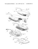
[0018]FIG. 1 is a partly disassembled, perspective view of a carry bag according to a first preferred embodiment of the invention,
[0019]FIG. 2 is a schematic, side view showing two stages in the evacuation of air from an enclosure forming part of the carry bag of FIG. 1,
[0020]FIG. 3 is a perspective view of a carry bag according to a second preferred embodiment of the invention showing a first stage of use,
[0021]FIG. 4 is a similar view to that of FIG. 3 but showing a second stage of use,
[0022]FIG. 5 is a similar view to that of FIGS. 3 and 4 but showing a third stage of use,
[0023]FIG. 6 is an enlarged and isolated view of a valve arrangement for suction means used in the carry bag as shown in FIG. 5,
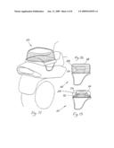
[0024]FIG. 7 is a perspective view of a carry bag according to a third preferred embodiment of the invention,
[0025]FIG. 8 is a rear view of the carry bag of FIG. 7,
[0026]FIG. 9 is a side view of the carry bag of FIG. 7 showing contents and an airtight inner bag enclosing same which has not been evacuated of air,
[0027]FIG. 10 is a view similar to that of FIG. 9 but in which air has been evacuated from the airtight inner bag to compress the contents against a rigid support wall of the carry bag,
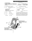
[0028]FIG. 11 is a perspective view of a carry bag according to a fourth preferred embodiment of the invention supported on a motorcycle,
[0029]FIG. 12 is a side view of the carry bag shown in FIG. 11 showing contents and an airtight inner bag enclosing same which has not been evacuated of air,
[0030]FIG. 13 is a view similar to that of FIG. 12 but in which air has been evacuated from the airtight inner bag to compress the contents against a rigid support wall of the carry bag,
[0031]FIG. 14 is a perspective view of a carry bag according to a fifth preferred embodiment of the invention showing a first stage of use,
[0032]FIG. 15 is a view similar to that of FIG. 14 but showing a second stage of use,
[0033]FIG. 16 is a view similar to that of FIG. 15 but showing a third stage of use,
[0034]FIG. 17 is a view similar to that of FIG. 16 but showing a fourth stage of use,
[0035]FIG. 18 is a view similar to that of FIG. 17 but showing a fifth stage of use,
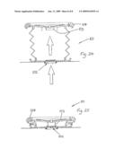
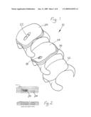
[0036]FIG. 19 is a side view of a carry bag according to a sixth preferred embodiment of the invention showing a first stage of use,
[0037]FIG. 20 is a view similar to that of FIG. 19 but showing a second stage of use,
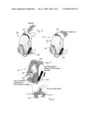
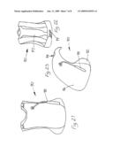
[0038]FIG. 21 is a rear view of a carry bag according to a seventh preferred embodiment of the invention showing a first stage of use,
[0039]FIG. 22 is a view similar to that of FIG. 21 but showing internal detail,
[0040]FIG. 23 is a perspective view of the carry bag of FIG. 21,
[0041]FIG. 24 is a side sectional view of a pump assembly that may be used in or with the carry bag of the invention, the pump assembly being shown in an open configuration, and
[0042]FIG. 25 is a similar view to that of FIG. 24, but showing the pump assembly in a closed configuration.
DETAILED DESCRIPTION OF THE PREFERRED EMBODIMENTS
[0043]The carry bag 10 shown in FIG. 1 includes a base plate 12, an airtight bag 14 with a ziplock opening 16 and a suction pump coupling 18 attached to the airtight bag 14, and a protective outer sleeve 20 with a suction pump 22 attached thereto. Air can be evacuated from the bag 14 to compress any contents 24 therein against the base plate 12 in the manner as shown schematically in FIG. 2 by connecting the suction pump 22 to the coupling 18 and operating same.
[0044]The carry bag 30 shown in FIGS. 3 to 5 is used, in a first stage, to receive contents through an outer sealable opening 32. The opening 32 is then closed to provide an airtight enclosure around the contents, and a hand pump 34 is then operated to evacuate air from the airtight enclosure. Flexible walls of the enclosure compress against the contents and hold them tightly in place. The one way valve 36 shown in FIG. 6 ensures that air cannot return into the enclosure during and after the operation of the hand pump 34.
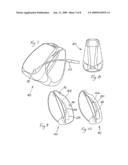
[0045]The carry bag 40 shown in FIGS. 7 to 10 is similar in structure and function to the carry bags described above, but is adapted specifically for use as a backpack. Like features between the carry bags have been assigned like numerals in the drawings. FIG. 10, in particular, identifies the inner bag 14 evacuated of air and its walls and the contents enclosed therewithin compressed against the rigid support wall 42.
[0046]The carry bag 50 shown in FIGS. 11 to 13 is adapted specifically for use as a pannier for a motorcycle. Again, like features have been assigned like numerals in the drawings.
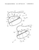
[0047]The carry bag 60 shown in FIGS. 14 to 18 is used, in a first stage, to receive contents 62 through an outer sealable opening 64. The opening 64 is then closed to provide an airtight enclosure 66 around the contents, and a hand pump 68 is then operated to evacuate air from the airtight enclosure. Flexible walls 69 of the enclosure compress against the contents and hold them tightly in place. The volume of space occupied by the carry bag 60 has thus been significantly reduced and the contents are prevented from movement relative to the bag.
[0048]The carry bag 70 shown in FIGS. 19 and 20 is similar in structure and function to the carry bags described above, but is adapted specifically for use as a backpack. FIG. 20, in particular, identifies an airtight bag 72 evacuated of air and its walls and the contents enclosed therewithin compressed against a rigid support wall 71.
[0049]The backpack 70 includes a stiffened base plate which serves as the support wall 71, an airtight bag 72 having a flexible wall with a ziplock opening 74 that provides an airtight resealable closure, a one-way air valve 76 mounted to the flexible wall, and a flexible air hose 78 connected at one end to the valve 76 and at the other end to a vacuum pump 80. Air can be evacuated from the bag 72 to compress contents 82 of the bag against the rigid support wall 71 in the manner as shown schematically in FIG. 20 by manually operating the vacuum pump 80 (according to a reciprocating or pumping motion of the pump). The outward flow of air from the bag 72 and through the air hose 78 is shown by arrows A, and the inward movement or compression of the flexible wall of the bag against the contents 82 is shown by arrows B. The backpack 70 can thus be worn with the aid of shoulder straps 84 by a user and, as the flexible wall of the airtight bag 72 firmly follows the outermost shape or profile of the contents 82, the contents will not move relative to the backpack during even violent movement of the user wearing same and the total volume of space occupied by the backpack 70 is significantly reduced.
[0050]The carry bag 90 shown in FIGS. 21 to 23 is similar in structure and function to the carry bags described above, but is adapted specifically for use as a medium sized backpack, also known as a daypack. It has a very light weight structure consisting of an airflow or breathable vest 92, a cavity 94 for a hydration container, say, for a sports beverage, and dual waterproof independent chambers (only a single chamber 96 shown) which are capable of being evacuated of air therewithin by a pump device 98. The daypack also has foam ribs 97 for back aeration and a waste strap 99 with a foam support.
[0051]The pump assembly 101 shown in FIGS. 24 and 25 may be used in or with any one of the carry bags described above. The pump assembly 101 utilizes two simple one way valves. An inner, smaller valve 102 maintains an airtight seal of the bag when the pump assembly is not in use. To this end, the pump assembly has been designed to close off the inner valve 102 by means of an extension 103 to a top moulding of a valve cap 104, which clamps down on the inner valve 102 when the pump assembly is shut after use. There is a bayonet style fitting between the top and bottom mouldings. The valves are of a conventional kind found on rubber inflatables and on simple foot pumps used for camping, and have thin rubber sheets that act as a type of diaphragm seal. The concave form of the valves ensures that they remain in a closed state unless forced open by pressure from beneath or within the carry bag
[0052]It will be readily apparent to persons skilled in the art that various modifications may be made in details of design and construction of the carry bag described above without departing from the scope or ambit of the present invention.
Claims:
1. A carry bag comprising flexible walls defining an enclosure adapted to
house contents of the bag, the enclosure having an opening for receiving
the contents therethrough, the opening being sealable for airtightness of
the enclosure, and means for evacuating air from the enclosure so as to
compress the walls against the contents to thereby restrain the contents
from movement.
2. The carry bag of claim 1 wherein the enclosure is an inner bag of the carry bag.
3. The carry bag of claim 1 wherein the air evacuating means is a suction pump.
4. The carry bag of claim 1 wherein the walls of the inner bag and its contents are compressed against a rigid support wall of the carry bag.
5. The carry bag of claim 1 wherein the carry bag is a backpack having a rigid support wall adapted to abut against the back of a user, and including an inner bag having flexible walls and a sealable opening that allows contents to be packed and sealed within the inner bag and for a vacuum to be created and maintained when the opening is sealed.
6. The carry bag of claim 5 wherein the inner bag is coupled to an air pump that, in use, evacuates air from the inner bag so as to cause the contents to be tightly secured against the rigid support wall, thereby reducing the volume of space occupied by the carry bag.
Description:
FIELD OF THE INVENTION
[0001]The present invention relates to improvements in carry bags and, in particular, to a carry bag that stabilizes its contents by the application of a vacuum. In an especially preferred form, the invention relates to a backpack which includes an inner airtight bag which may be evacuated of air by a suction device for compressing the bag tightly and sealably against the contents of the bag.
BACKGROUND OF THE INVENTION
[0002]For ease of understanding, the term "carry bag" as used in this specification embraces such items as backpacks, rucksacks, satchels, knapsacks, handbags, suitcases, riding or saddle bags, duffel bags, motorcycle panniers, and webbed carry pouches, such as those used by the military. All of these carry bags are designed to reliably envelope, and provide some degree of restricted access to, their contents, as well as provide a means of conveyance to the user, such as by handles, straps, buckles or latches.
[0003]However, there are numerous well known problems or limitations of such carry bags, one of which is the inability to tightly secure the carry bag contents. For example, prolonged chaotic movement, as is the case with a runner's backpack, can cause damage to, and rearrangement of, its contents, leading to discomfort to the bearer of the carry bag. The problem is exacerbated when the carry bag is not full, notwithstanding the careful and often time consuming packing of contents and the use of securing straps incorporated in some bags.
[0004]Another problem arises where the carry bag is oversized relative to its contents. It is desirable in any circumstance of transportation with a carry bag for the contents to occupy a minimum volume for avoiding snagging the carry bag, for maximizing packing space externally of the carry bag, and for optimizing the centre of mass with regard to the transporting person or vehicle. Where a carry bag is not packed to capacity or the contents are compressible, it is difficult to efficiently reduce the overall volume of the carry bag and its contents. Some carry bags include a means of restricting volume by a strap or drawstring, but these devices are only partly effective in reducing volume and may malfunction during prolonged periods of use.
[0005]Waterproofing of carry bags is another problem that has not generally been addressed. Many carry bags are designed for circumstances where rain or at least partial immersion in water is possible. They often employ watertight material and a means of enclosure that averts entry of rain water, such as a drawstring controlled opening with a flap cover. However, these carry bags are ineffective in heavy rain and cannot withstand immersion in water, and thus require, as a special precaution, the contents to be separately waterproofed before being packed into the carry bag.
[0006]Although various attempts have been made to address any one or some of the aforementioned problems and limitations, no carry bags have yet been identified in the prior art by the inventor that address all of those problems and limitations, and provide a sealable, waterproof carry bag which comprises, or includes an inner bag which comprises, flexible walls in order to restrain its contents from movement by compressing the walls against the contents when air is evacuated from the bag by a suction device.
[0007]For example, prior art patent document WO 03/056975 discloses an adjustable backpack compression-suspension system which allows the pack to be easily shifted from the load carrying position at the back of the wearer to an access position at the side or front of the wearer, which system stabilizes and compresses the load in the carrying position. The pack has a waist belt at its lower edge, and opposite side edges of the pack are tethered to the sides of the belt by the compression-suspension system which attaches to the pack by a strap at multiple spaced-apart locations. The system includes several straps which are subject to tensioning force and thus adjustable to laterally compress and stabilize the pack and its contents in a comfortable position.
[0008]Prior art patent document U.S. Pat. No. 6,047,413 discloses a protective garment having a backpack portion adapted to conform to equipment worn on a back of a wearer of the protective garment. The backpack portion includes an outer protective layer that is gathered, and a plurality of elastic members are connected to an interior surface of the outer protective layer so that it is drawn toward and conforms to the worn equipment.
[0009]Other prior art apparatus and methods for compressing carry bags and their contents are disclosed in patent documents U.S. Pat. No. 5,987,644; U.S. Pat. No. 5,361,955; and U.S. Pat. No. 6,024,265.
[0010]None of the aforementioned prior art documents disclose the use of a vacuum created after packing and sealing contents into an airtight inner bag contained within a carry bag to reduce the volume of the inner bag for the purpose of compressing the contents against the carry bag and hence immobilize the contents.
[0011]It is, therefore, an object of the present invention to overcome, or at least substantially ameliorate, the shortcomings and disadvantages of the aforementioned prior art, or at least provide a useful alternative.
SUMMARY OF THE INVENTION
[0012]According to the invention, there is provided a carry bag comprising flexible walls defining an enclosure adapted to house contents of the bag, the enclosure having an opening for receiving the contents therethrough, the opening being sealable for airtightness of the enclosure, and means for evacuating air from the enclosure so as to compress the walls against the contents to thereby restrain the contents from movement.
[0013]In a preferred form, the enclosure is an inner bag of the carry bag.
[0014]Preferably, the air evacuating means is a suction pump.
[0015]It is preferred that the walls of the inner bag and its contents are compressed against a rigid support wall of the carry bag.
[0016]In a particularly preferred embodiment, the carry bag is a backpack having a rigid support wall adapted to abut against the back of a user, and including an inner bag having flexible walls and a sealable opening that allows contents to be packed and sealed within the inner bag and for a vacuum to be created and maintained when the opening is sealed. The inner bag is coupled to an air pump that, in use, evacuates air from the inner bag so as to cause the contents to be tightly secured against the rigid support wall, thereby reducing the volume of space occupied by the carry bag.
BRIEF SUMMARY OF THE DRAWINGS
[0017]In order that the invention may be readily understood and put into practical effect, reference will now be made to the accompanying drawings, in which:
[0018]FIG. 1 is a partly disassembled, perspective view of a carry bag according to a first preferred embodiment of the invention,
[0019]FIG. 2 is a schematic, side view showing two stages in the evacuation of air from an enclosure forming part of the carry bag of FIG. 1,
[0020]FIG. 3 is a perspective view of a carry bag according to a second preferred embodiment of the invention showing a first stage of use,
[0021]FIG. 4 is a similar view to that of FIG. 3 but showing a second stage of use,
[0022]FIG. 5 is a similar view to that of FIGS. 3 and 4 but showing a third stage of use,
[0023]FIG. 6 is an enlarged and isolated view of a valve arrangement for suction means used in the carry bag as shown in FIG. 5,
[0024]FIG. 7 is a perspective view of a carry bag according to a third preferred embodiment of the invention,
[0025]FIG. 8 is a rear view of the carry bag of FIG. 7,
[0026]FIG. 9 is a side view of the carry bag of FIG. 7 showing contents and an airtight inner bag enclosing same which has not been evacuated of air,
[0027]FIG. 10 is a view similar to that of FIG. 9 but in which air has been evacuated from the airtight inner bag to compress the contents against a rigid support wall of the carry bag,
[0028]FIG. 11 is a perspective view of a carry bag according to a fourth preferred embodiment of the invention supported on a motorcycle,
[0029]FIG. 12 is a side view of the carry bag shown in FIG. 11 showing contents and an airtight inner bag enclosing same which has not been evacuated of air,
[0030]FIG. 13 is a view similar to that of FIG. 12 but in which air has been evacuated from the airtight inner bag to compress the contents against a rigid support wall of the carry bag,
[0031]FIG. 14 is a perspective view of a carry bag according to a fifth preferred embodiment of the invention showing a first stage of use,
[0032]FIG. 15 is a view similar to that of FIG. 14 but showing a second stage of use,
[0033]FIG. 16 is a view similar to that of FIG. 15 but showing a third stage of use,
[0034]FIG. 17 is a view similar to that of FIG. 16 but showing a fourth stage of use,
[0035]FIG. 18 is a view similar to that of FIG. 17 but showing a fifth stage of use,
[0036]FIG. 19 is a side view of a carry bag according to a sixth preferred embodiment of the invention showing a first stage of use,
[0037]FIG. 20 is a view similar to that of FIG. 19 but showing a second stage of use,
[0038]FIG. 21 is a rear view of a carry bag according to a seventh preferred embodiment of the invention showing a first stage of use,
[0039]FIG. 22 is a view similar to that of FIG. 21 but showing internal detail,
[0040]FIG. 23 is a perspective view of the carry bag of FIG. 21,
[0041]FIG. 24 is a side sectional view of a pump assembly that may be used in or with the carry bag of the invention, the pump assembly being shown in an open configuration, and
[0042]FIG. 25 is a similar view to that of FIG. 24, but showing the pump assembly in a closed configuration.
DETAILED DESCRIPTION OF THE PREFERRED EMBODIMENTS
[0043]The carry bag 10 shown in FIG. 1 includes a base plate 12, an airtight bag 14 with a ziplock opening 16 and a suction pump coupling 18 attached to the airtight bag 14, and a protective outer sleeve 20 with a suction pump 22 attached thereto. Air can be evacuated from the bag 14 to compress any contents 24 therein against the base plate 12 in the manner as shown schematically in FIG. 2 by connecting the suction pump 22 to the coupling 18 and operating same.
[0044]The carry bag 30 shown in FIGS. 3 to 5 is used, in a first stage, to receive contents through an outer sealable opening 32. The opening 32 is then closed to provide an airtight enclosure around the contents, and a hand pump 34 is then operated to evacuate air from the airtight enclosure. Flexible walls of the enclosure compress against the contents and hold them tightly in place. The one way valve 36 shown in FIG. 6 ensures that air cannot return into the enclosure during and after the operation of the hand pump 34.
[0045]The carry bag 40 shown in FIGS. 7 to 10 is similar in structure and function to the carry bags described above, but is adapted specifically for use as a backpack. Like features between the carry bags have been assigned like numerals in the drawings. FIG. 10, in particular, identifies the inner bag 14 evacuated of air and its walls and the contents enclosed therewithin compressed against the rigid support wall 42.
[0046]The carry bag 50 shown in FIGS. 11 to 13 is adapted specifically for use as a pannier for a motorcycle. Again, like features have been assigned like numerals in the drawings.
[0047]The carry bag 60 shown in FIGS. 14 to 18 is used, in a first stage, to receive contents 62 through an outer sealable opening 64. The opening 64 is then closed to provide an airtight enclosure 66 around the contents, and a hand pump 68 is then operated to evacuate air from the airtight enclosure. Flexible walls 69 of the enclosure compress against the contents and hold them tightly in place. The volume of space occupied by the carry bag 60 has thus been significantly reduced and the contents are prevented from movement relative to the bag.
[0048]The carry bag 70 shown in FIGS. 19 and 20 is similar in structure and function to the carry bags described above, but is adapted specifically for use as a backpack. FIG. 20, in particular, identifies an airtight bag 72 evacuated of air and its walls and the contents enclosed therewithin compressed against a rigid support wall 71.
[0049]The backpack 70 includes a stiffened base plate which serves as the support wall 71, an airtight bag 72 having a flexible wall with a ziplock opening 74 that provides an airtight resealable closure, a one-way air valve 76 mounted to the flexible wall, and a flexible air hose 78 connected at one end to the valve 76 and at the other end to a vacuum pump 80. Air can be evacuated from the bag 72 to compress contents 82 of the bag against the rigid support wall 71 in the manner as shown schematically in FIG. 20 by manually operating the vacuum pump 80 (according to a reciprocating or pumping motion of the pump). The outward flow of air from the bag 72 and through the air hose 78 is shown by arrows A, and the inward movement or compression of the flexible wall of the bag against the contents 82 is shown by arrows B. The backpack 70 can thus be worn with the aid of shoulder straps 84 by a user and, as the flexible wall of the airtight bag 72 firmly follows the outermost shape or profile of the contents 82, the contents will not move relative to the backpack during even violent movement of the user wearing same and the total volume of space occupied by the backpack 70 is significantly reduced.
[0050]The carry bag 90 shown in FIGS. 21 to 23 is similar in structure and function to the carry bags described above, but is adapted specifically for use as a medium sized backpack, also known as a daypack. It has a very light weight structure consisting of an airflow or breathable vest 92, a cavity 94 for a hydration container, say, for a sports beverage, and dual waterproof independent chambers (only a single chamber 96 shown) which are capable of being evacuated of air therewithin by a pump device 98. The daypack also has foam ribs 97 for back aeration and a waste strap 99 with a foam support.
[0051]The pump assembly 101 shown in FIGS. 24 and 25 may be used in or with any one of the carry bags described above. The pump assembly 101 utilizes two simple one way valves. An inner, smaller valve 102 maintains an airtight seal of the bag when the pump assembly is not in use. To this end, the pump assembly has been designed to close off the inner valve 102 by means of an extension 103 to a top moulding of a valve cap 104, which clamps down on the inner valve 102 when the pump assembly is shut after use. There is a bayonet style fitting between the top and bottom mouldings. The valves are of a conventional kind found on rubber inflatables and on simple foot pumps used for camping, and have thin rubber sheets that act as a type of diaphragm seal. The concave form of the valves ensures that they remain in a closed state unless forced open by pressure from beneath or within the carry bag
[0052]It will be readily apparent to persons skilled in the art that various modifications may be made in details of design and construction of the carry bag described above without departing from the scope or ambit of the present invention.
User Contributions:
Comment about this patent or add new information about this topic:
| People who visited this patent also read: | |
| Patent application number | Title |
|---|---|
| 20120274515 | POSITIONING SYSTEM AND METHOD |
| 20120274514 | BEAMFORMING METHODS AND APPARATUSES |
| 20120274513 | Method and a System for Configuring a Beam Forming Antenna in a Communication Network |
| 20120274512 | Signal Processing Method, Device and System |
| 20120274511 | Satellite Based Augmentation System |
Images included with this patent application:
 |  |
 |  |
 |  |
 |  |
 |
| Similar patent applications: | |
| Date | Title |
|---|---|
| 2012-07-05 | Vacuum mounted carrier for a vehicle |
| 2012-08-02 | Strap-mounted stabilizer for a bicycle carrier |
| 2012-09-13 | Stabilized cargo box for a vehicle rack system |
| 2012-08-16 | System for the compartmentalization of object carrying cabins |
| 2011-01-27 | Actuable load carrier craddle |
| New patent applications in this class: | |
| Date | Title |
|---|---|
| 2016-04-14 | Expandable carry pouch with variable compression |
| Top Inventors for class "Package and article carriers" | |
| Rank | Inventor's name |
|---|---|
| 1 | Chris Sautter |
| 2 | Zac Elder |
| 3 | Peter Douglas Hubbard |
| 4 | Douglas Harland Murdoch |
| 5 | Jeffrey M. Aftanas |