Patent application title: Induction powered ladle bottom nozzle
Inventors:
Earl K Stanley (Naples, FL, US)
John R. Mott (Walkersville, MD, US)
IPC8 Class: AB22D3700FI
USPC Class:
222590
Class name: Dispensing processes of dispensing molten metal
Publication date: 2009-06-11
Patent application number: 20090145933
ainer for molten metal (5) is provided with an
outlet nozzle (4) that allows a stream of molten metal to flow by heating
the nozzle (4) to the melting temperature of the metal (5). The nozzle
(4) is, for example, tubular and made of AI2O3 or SiO2 and is surrounded
by a graphite tube (8) in thermal contact with the nozzle (4). The nozzle
(4) is heated by heating the surrounding graphite tube (S) inductively.
Once the temperature of the nozzle (4) exceeds the liquidus temperature
of the metal (5) in the ladle (2), the metal (5) will flow out of the
ladle (2) through the nozzle (4).Claims:
1. An outlet for a ladle comprising a nozzle configured to be heated and
allow metal to flow therethrough when heated and to block flow when not
heated.
2. An outlet for a ladle according to claim 1 further comprising a graphite susceptor in thermal contact with the nozzle, and an induction coil for heating the susceptor.
3. An outlet for a ladle according to claim 2 in combination with a container for holding molten metal.
4. A container for holding molten metal comprising an outlet nozzle and a cooled induction coil for heating said nozzle when electrical power is applied to said coil and for cooling said nozzle when said electrical power is reduced or terminated.
5. A container according to claim 4 wherein said nozzle comprises graphite.
6. A container according to claim 4 further comprising a graphite susceptor in thermal contact with said nozzle.
7. A method for controlling the discharge of molten metal from a container comprising providing said container with an outlet nozzle, providing means for heating said outlet nozzle, and controlling the temperature of said outlet nozzle.
8. A method according to claim 7 further comprising applying a vacuum to said container.Description:
TECHNICAL FIELD
[0001]This application relates to an inductively powered nozzle for controlling the flow of metal from a ladle or other vessel containing molten metal.
BACKGROUND
[0002]It is known to use ladles to contain molten metal in the production of such metals. Typically, the ladle has an outlet at the bottom, which includes a valve that can be controlled. These valves are problematic, however, because they are expensive and require frequent repair or replacement.
SUMMARY OF THE INVENTION
[0003]In accordance with the invention a ladle or other container for molten metal is provided with an outlet nozzle that is easily controlled and less expensive. In one embodiment, a stream of molten metal, e.g., silicon flows through a tubular refractory nozzle by heating the nozzle to the melting temperature of the metal. The nozzle is, for example, tubular and made of Al203 or SiO2 and is surrounded by a graphite tube in thermal contact with the nozzle. The nozzle is heated by heating the surrounding graphite tube inductively. Once the temperature of the nozzle exceeds the liquidus temperature of the metal in the ladle, the metal will flow out of the ladle through the nozzle.
[0004]Alternately the nozzle may be made entirely of graphite, if the impurities that contact with the graphite may impart to the metal are not of concern.
[0005]The rate of flow through the nozzle may be controlled in part also by applying a vacuum to the ladle proper, as is known in the industry. If the vacuum is sufficient, the flow can be controlled very accurately, from a few drops per minute to full flow through the nozzle. It can also be stopped completely, if there is such a need, and re-started later in the process. Thus, accurate control of flow through the nozzle may also be obtained by combining the nozzle of the invention with known techniques.
BRIEF DESCRIPTION OF THE DRAWINGS
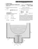
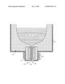
[0006]The figure is a vertical cross section of a ladle having a nozzle in accordance with the invention.
DETAILED DESCRIPTION
[0007]With reference to the figure, a ladle 2, which is preferably made of inductively transparent material, as known in the art, includes an outlet 4. The ladle is used to refine metal 5, such as Si that is to be dispensed through the outlet in the molten state and may include a refractory material 3. The metal to be refined may be heated by any known means, such as by inductive heating. The outlet comprises a nozzle 6 made of a material that has a melting point higher than that of the material to be dispensed, which is preferably surrounded by insulating refractory material 7. For example, if the metal to be dispensed is Si, the nozzle may be made of Al2O3, SiO2, ZrO2 or other suitable refractory.
[0008]In the preferred embodiment, the nozzle 6 is engaged with the outlet of the ladle and may be supported by contact with a graphite susceptor tube 8 or by other means. The susceptor tube 8 preferably surrounds the nozzle and is configured to transfer heat to the nozzle 6 to liquefy the metal to be dispensed.
[0009]The heater tube and nozzle are preferably not in physical contact at all times because their coefficients of expansion differ, but they are configured and positioned such that they are in thermal contact whereby heat from the graphite heater is effectively transferred to the nozzle.
[0010]The graphite susceptor is preferably heated by energy received from induction coil 10. This has been found to be very efficient and to result in good control of the temperature of the nozzle 6 and good control of the flow through the nozzle, particularly when used in combination with a variable vacuum applied to the ladle.
[0011]The nozzle is preferably about twelve inches in length and extends beyond the bottom of the heater by several inches, preferably about 3 inches. Extending the end of the nozzle beyond the susceptor promotes cooling of the nozzle when heating is terminated.
[0012]The nozzle may be of various diameters. Preferably the diameter is from about one-half inch to about one inch. This diameter allows adequate flow of molten metal when the nozzle is heated and permits good control over the flow rate of the metal by application of vacuum to the ladle. Such diameters permit vacuum control of the flow rate during heating and allow the nozzle to clog quickly by cooling of the metal when the flow rate is substantially reduced and heating terminated.
[0013]While the nozzle is preferably heated inductively, other methods of heating are possible. For example, the graphite tube may be a resistor and heated by passing electrical current through it directly with provided leads.
[0014]If vacuum control of the flow rate is not to be used, the diameter is preferably smaller, e.g.; about one-quarter inch. When the diameter is that small, it is possible to shut off flow by simply terminating the heating.
[0015]In another embodiment, the nozzle is made of graphite and heated inductively directly by the induction coil, the power to the coil controlling the temperature in the nozzle and the flow rate of the metal. In either embodiment, the induction coil is preferably water cooled, and the cooling effect due to the presence of the water causes the metal to solidify in the nozzle more rapidly to reduce or stop flow when the power to the coil is reduced or shut off.
[0016]The graphite nozzle can also be cast en bloc with the induction coil with a castable refractory, which improves conduction of heat from the nozzle and metal to the water in a copper induction coil. The combination of the cooling effect of the induction coil and vacuum control provides fine flow control of the molten metal. Additionally, an oxide refractory nozzle, as disclosed above, can be placed inside a close-fitting graphite susceptor tube and still be heated and cooled by the induction coil.
[0017]Modifications within the scope of the appended claims will be apparent to those of skill in the art.
Claims:
1. An outlet for a ladle comprising a nozzle configured to be heated and
allow metal to flow therethrough when heated and to block flow when not
heated.
2. An outlet for a ladle according to claim 1 further comprising a graphite susceptor in thermal contact with the nozzle, and an induction coil for heating the susceptor.
3. An outlet for a ladle according to claim 2 in combination with a container for holding molten metal.
4. A container for holding molten metal comprising an outlet nozzle and a cooled induction coil for heating said nozzle when electrical power is applied to said coil and for cooling said nozzle when said electrical power is reduced or terminated.
5. A container according to claim 4 wherein said nozzle comprises graphite.
6. A container according to claim 4 further comprising a graphite susceptor in thermal contact with said nozzle.
7. A method for controlling the discharge of molten metal from a container comprising providing said container with an outlet nozzle, providing means for heating said outlet nozzle, and controlling the temperature of said outlet nozzle.
8. A method according to claim 7 further comprising applying a vacuum to said container.
Description:
TECHNICAL FIELD
[0001]This application relates to an inductively powered nozzle for controlling the flow of metal from a ladle or other vessel containing molten metal.
BACKGROUND
[0002]It is known to use ladles to contain molten metal in the production of such metals. Typically, the ladle has an outlet at the bottom, which includes a valve that can be controlled. These valves are problematic, however, because they are expensive and require frequent repair or replacement.
SUMMARY OF THE INVENTION
[0003]In accordance with the invention a ladle or other container for molten metal is provided with an outlet nozzle that is easily controlled and less expensive. In one embodiment, a stream of molten metal, e.g., silicon flows through a tubular refractory nozzle by heating the nozzle to the melting temperature of the metal. The nozzle is, for example, tubular and made of Al203 or SiO2 and is surrounded by a graphite tube in thermal contact with the nozzle. The nozzle is heated by heating the surrounding graphite tube inductively. Once the temperature of the nozzle exceeds the liquidus temperature of the metal in the ladle, the metal will flow out of the ladle through the nozzle.
[0004]Alternately the nozzle may be made entirely of graphite, if the impurities that contact with the graphite may impart to the metal are not of concern.
[0005]The rate of flow through the nozzle may be controlled in part also by applying a vacuum to the ladle proper, as is known in the industry. If the vacuum is sufficient, the flow can be controlled very accurately, from a few drops per minute to full flow through the nozzle. It can also be stopped completely, if there is such a need, and re-started later in the process. Thus, accurate control of flow through the nozzle may also be obtained by combining the nozzle of the invention with known techniques.
BRIEF DESCRIPTION OF THE DRAWINGS
[0006]The figure is a vertical cross section of a ladle having a nozzle in accordance with the invention.
DETAILED DESCRIPTION
[0007]With reference to the figure, a ladle 2, which is preferably made of inductively transparent material, as known in the art, includes an outlet 4. The ladle is used to refine metal 5, such as Si that is to be dispensed through the outlet in the molten state and may include a refractory material 3. The metal to be refined may be heated by any known means, such as by inductive heating. The outlet comprises a nozzle 6 made of a material that has a melting point higher than that of the material to be dispensed, which is preferably surrounded by insulating refractory material 7. For example, if the metal to be dispensed is Si, the nozzle may be made of Al2O3, SiO2, ZrO2 or other suitable refractory.
[0008]In the preferred embodiment, the nozzle 6 is engaged with the outlet of the ladle and may be supported by contact with a graphite susceptor tube 8 or by other means. The susceptor tube 8 preferably surrounds the nozzle and is configured to transfer heat to the nozzle 6 to liquefy the metal to be dispensed.
[0009]The heater tube and nozzle are preferably not in physical contact at all times because their coefficients of expansion differ, but they are configured and positioned such that they are in thermal contact whereby heat from the graphite heater is effectively transferred to the nozzle.
[0010]The graphite susceptor is preferably heated by energy received from induction coil 10. This has been found to be very efficient and to result in good control of the temperature of the nozzle 6 and good control of the flow through the nozzle, particularly when used in combination with a variable vacuum applied to the ladle.
[0011]The nozzle is preferably about twelve inches in length and extends beyond the bottom of the heater by several inches, preferably about 3 inches. Extending the end of the nozzle beyond the susceptor promotes cooling of the nozzle when heating is terminated.
[0012]The nozzle may be of various diameters. Preferably the diameter is from about one-half inch to about one inch. This diameter allows adequate flow of molten metal when the nozzle is heated and permits good control over the flow rate of the metal by application of vacuum to the ladle. Such diameters permit vacuum control of the flow rate during heating and allow the nozzle to clog quickly by cooling of the metal when the flow rate is substantially reduced and heating terminated.
[0013]While the nozzle is preferably heated inductively, other methods of heating are possible. For example, the graphite tube may be a resistor and heated by passing electrical current through it directly with provided leads.
[0014]If vacuum control of the flow rate is not to be used, the diameter is preferably smaller, e.g.; about one-quarter inch. When the diameter is that small, it is possible to shut off flow by simply terminating the heating.
[0015]In another embodiment, the nozzle is made of graphite and heated inductively directly by the induction coil, the power to the coil controlling the temperature in the nozzle and the flow rate of the metal. In either embodiment, the induction coil is preferably water cooled, and the cooling effect due to the presence of the water causes the metal to solidify in the nozzle more rapidly to reduce or stop flow when the power to the coil is reduced or shut off.
[0016]The graphite nozzle can also be cast en bloc with the induction coil with a castable refractory, which improves conduction of heat from the nozzle and metal to the water in a copper induction coil. The combination of the cooling effect of the induction coil and vacuum control provides fine flow control of the molten metal. Additionally, an oxide refractory nozzle, as disclosed above, can be placed inside a close-fitting graphite susceptor tube and still be heated and cooled by the induction coil.
[0017]Modifications within the scope of the appended claims will be apparent to those of skill in the art.
User Contributions:
Comment about this patent or add new information about this topic:
Images included with this patent application:
 |  |
| Similar patent applications: | |
| Date | Title |
|---|---|
| 2010-10-07 | Water probe for bottom loading water cooler |
| 2011-12-08 | Dispensing container with bottom valve |
| 2012-10-18 | Method and apparatus for prevention and detection of phase separation in storage tanks |
| 2010-01-14 | Pumping device with collapsible nozzle |
| 2010-04-08 | Controlled collapse bottle |
| New patent applications in this class: | |
| Date | Title |
|---|---|
| 2018-01-25 | System and method for transporting molen metal |
| 2016-03-31 | Method of transferring molten metal from a vessel |
| 2016-02-04 | Nozzle sand and method of use and operation |
| 2016-01-28 | Bottom-pouring-type ladle, and melt-pouring method using it |
| 2014-10-30 | Die casting nozzle and method for operating a die casting nozzle |
| New patent applications from these inventors: | |
| Date | Title |
|---|---|
| 2010-06-10 | Method and apparatus for making fiber composite article |
| Top Inventors for class "Dispensing" | |
| Rank | Inventor's name |
|---|---|
| 1 | Nick E. Ciavarella |
| 2 | John J. Mcnulty |
| 3 | Robert L. Quinlan |
| 4 | Andrew Jones |
| 5 | Heiner Ophardt |