Patent application title: REINFORCING BODY MADE OF FIBER-REINFORCED PLASTIC
Inventors:
Kenichi Tsukamoto (Meerbusch, DE)
IPC8 Class: AE04C507FI
USPC Class:
52686
Class name: Openwork; e.g., truss, trellis, grille, screen, frame, or rebar chair spacer-positioner; e.g., rebar chair crossed supported member type
Publication date: 2009-06-11
Patent application number: 20090145074
a reinforcing body (1) for buildings, in
particular for buildings made of concrete, said reinforcing body
comprising a plurality of reinforcing rods (2a, 2b) which are connected
together by connecting agents (5) at connecting points (4) and which are
made of fiber-reinforced plastic, said connecting agents (5) comprising
connection fibers (6) which are embedded in a plastic matrix (7) and
which are wound several times about the reinforcing rods (2a, 2b) at the
connecting points (4).Claims:
1. A reinforcing body (1) for buildings, in particular for buildings made
of concrete, said reinforcing body comprising a plurality of reinforcing
rods (2a, 2b) which are connected together by connecting agents (5) at
connecting points (4) and which are made of fiber-reinforced plastic,
said connecting agents (5) comprising connection fibers (6) which are
embedded in a plastic matrix (7),characterized in that the connection
fibers (6) are wound several times about the reinforcing rods (2a, 2b) at
the connecting points (4) in such a way that, when a tensile or
compressive stress acts transversally to the longitudinal axis of a first
reinforcing rod (2a, 2b) in the longitudinal direction of a second
reinforcing rod (2b, 2a), a connecting force S which satisfies the
equation S>0.3*AS*RB is achieved for a single connection
point (4), where AS describes the cross-sectional area of the second
reinforcing rod (2b, 2a) and RB describes the permissible working
stress of the second reinforcing rod (2b, 2a).
2. The reinforcing body of claim 1, characterized in that the connection fibers (6) are wound in different directions about a connection point (4).
3. The reinforcing body of claim 1, characterized in that the connection fibers (6) at a reinforcing rod (2a, 2b) or at both reinforcing rods (2a, 2b) each intersect at least one point.
4. The reinforcing body of claim 1, characterized in that the connection fibers (6) include glass fibers and/or aramide fibers and/or carbon fibers.
5. The reinforcing body of claim 1, characterized in that the connection fibers (6) and/or the plastic in the plastic matrix (7) at the connecting points (4) consist of the same material as the fibers and/or plastic in the reinforcing rods (2a, 2b).
6. The reinforcing body of claim 1, characterized in that the reinforcing rods (2a, 2b) have external profiling which is specifically embodied as a threaded profile or preferably in the form of a screw thread.
7. The reinforcing body of claim 1, characterized in that the reinforcing rods (2a, 2b) are arranged at least substantially perpendicular to one another.
8. The reinforcing body of claim 1, characterized in that the reinforcing rods (2a, 2b) are arranged at least substantially two-dimensionally in the form of a mat (1, 10).
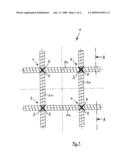
9. The reinforcing body of claim 8, characterized in that all the reinforcing rods (2a, 2b) extend in a straight line, wherein a first group of reinforcing rods (2a) extends in a first plane (3a) and wherein a second group of reinforcing rods (2b) extends in a second plane (3b) running parallel to the first plane (3a).
10. The reinforcing body of claim 1, characterized in that the reinforcing rods (2a, 2b) form a three-dimensional reinforcing body (11, 12), in particular a reinforcing pile (11) or a reinforcing cage (12).
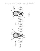
11. The reinforcing body of claim 10, characterized in that at least individual reinforcing rods (2a, 2b) are curved in sections thereof or throughout.
12. The reinforcing body of claim 11, characterized in that a plurality of reinforcing rods (2a) are embodied in circular shape and are connected on the inside and/or the outside to a plurality of reinforcing rods (2b) extending at least approximately in a straight line to form a tubular reinforcing body (11).
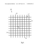
13. The reinforcing body of claim 11, characterized in that a plurality of reinforcing rods (2a) are bent at an angle at least in sections thereof and are embodied in the shape of a square and are connected on the inside and/or on the outside to a plurality of reinforcing rods (2b) extending at least approximately in a straight line to form a cuboidal reinforcing body (12).
14. The reinforcing body of claim 1, characterized in that the plastic matrix (7) is fully hardened with the connection fibers (6) embedded therein.
15. The reinforcing body according to claim 1, characterized in that said reinforcing body is embodied as a prepreg, the plastic matrix (7) with the connection fibers (6) embedded therein being pre-hardened to a certain degree such that a certain degree of mobility is provided at the connecting points (4), wherein said plastic matrix (7) can be fully hardened by the application of heat.Description:
[0001]The present invention relates to a reinforcing body for structures,
according to the preamble of claim 1, preferably for structures made of
concrete or of other hydraulically setting materials, which may also be
mixed with other materials, for example with ground materials. The
reinforcing body comprises a plurality of reinforcing rods each
consisting of fiber-reinforced plastic and connected to one another at
connecting points by connecting agents. The individual reinforcing rods
can be of any length and cross-sectional shape, and have end portions of
any shape. The reinforcing rods preferably have a round, in particular at
least approximately circular cross-section and an axial extension that is
at least substantially straight.
[0002]The use of reinforcing bodies is generally known. They are used to increase mechanical strength, in particular for increasing the tensile strength of concrete structures. Concrete is a principal component of many structures, for example of buildings or bridges. However, in order to withstand the stresses that arise during use, it is essential that reinforcing struts, especially reinforcing struts that transfer tensile forces, be embedded as reinforcement in the concrete. Steel reinforcing rods and reinforcing bodies have proved over many years to provide suitable reinforcement of concrete buildings.
[0003]However, steel reinforcements can corrode in situations where the working conditions are particularly tough, especially in damp or chemically aggressive environments. Corrosion of the steel reinforcements leads to a reduction in the adhesive forces and/or to deterioration in the bedding between steel and concrete, which results in cracks and in flaking of the concrete. Not only does this cause an unaesthetic appearance of the buildings affected, but the corrosion of the steel reinforcements can lead above all to weakening and ultimately even to final collapse of the structure, thus signifying a major hazard. Due to the damage caused to structures by corrosion, substantial levels of repair and maintenance expense are necessary in order to avoid any further risks.
[0004]Reinforcement with non-corroding or corrosion-resistant reinforcing struts, for example with reinforcing struts or reinforcing bodies that are galvanized or epoxy-coated or made of stainless steel, are known as a means of preventing corrosion-related problems. However, such reinforcing bodies can only be used to a limited extent in certain environmental conditions, for example where chlorine is present in high concentrations. In addition, they involve very high costs, which has hitherto opposed any comprehensive use.
[0005]Furthermore, there are also detrimental impacts on the environment. Since the aforementioned corrosion-protected reinforcing bodies are too expensive, it is recommended that concrete be applied with a thickness of between 75 mm and 120 mm to conventional steel reinforcements in order to cover the steel reinforcing struts sufficiently and in this way to try and prevent them from corroding. Non-renewable natural resources are severely stressed due to the large amount of concrete involved. In addition, unnecessarily large amounts of CO2 are emitted due to the increased production of cement.
[0006]For this reason, the use of reinforcing bodies made of fiber-reinforced plastic, also referred to internationally as "FRP-rebars" ("FRP" being short for "fiber reinforced plastic"), is proposed as a substitute for corrodible steel reinforcements. Such FRP reinforcing bodies are resistant to corrosion and relatively inexpensive, so the aforementioned problems with corrosion can be combated permanently and efficaciously at low cost.
[0007]Fiber-reinforced plastics are composite fiber materials in which the plastic is combined with fibers made of a different material in order to obtain synergy effects and properties that are improved in the desired direction, especially to obtain mechanically improved properties. The fibers used can be glass fibers, for example, which are preferably embedded in the plastic with "unidirectional" fiber orientation in the longitudinal direction of a rod profile. A plurality of fibers aligned parallel to one another and which can have a diameter of between 10 and 30 μm, for example, is thus surrounded by a matrix of plastic resin. The fibers give the composite material its high strength in the longitudinal direction, while the resin matrix serves to fix the fibers in position and simultaneously to protect them against damaging influences.
[0008]In addition to individual reinforcing rods, reinforcing bodies of the kind initially specified and made of fiber-reinforced plastics, in particular, are also known. The connecting agents used to connect the individual plastic rods to one another are often wires, however, particularly conventional tying wires, which in turn are prone to corrosion and can lead to the aforementioned problems. In addition, these wire connections are only a temporary form of securing during transport and assembly, whereas after the concrete has hardened they can no longer make any significant contribution to increasing the tensile and shearing forces of the concrete body. Such reinforcing bodies comprising reinforcing rods connected by wires are known, for example, from document WO 01/26974 A2.
[0009]Cable ties made of plastic, known from the field of electrical installation, are also used for connecting the individual rods. By this means, however, as with the use of wire, only an extremely limited strength can be achieved, and the individual reinforcing rods are still always moved relatively easily in relation to one another. These connecting agents merely result, likewise, in reinforcing bodies which do not optimally increase the load-bearing capacity of the concrete body.
[0010]It is also known to intermesh single reinforcing rods made of fiber-reinforced plastic, but this involves considerable production complexity and correspondingly high costs. In the case of intermeshing, it is also necessary to deform at least individual reinforcing rods, with the result that this type of connection cannot be used in the case of fully hardened reinforcing rods.
[0011]A planar lattice fabric of the kind initially specified, and which can also be used as a reinforcing body, is known from document EP 0 387 968 A1 and from the associated German document DE 690 02 071 T2, in which the connecting agents comprise a warp yarn that is woven as a connection fiber into a plastic matrix. However, the connection fibers in this leno fabric, with a very small weft bending index of maximum 0.03, are curved to only a very small extent, with the result that they run almost in a straight line, substantially parallel to a reinforcing rod, and at the connecting points contact the transversely running reinforcing rods merely from one side over a highly limited circumferential portion. This type of interweaving or intermeshing can only result, therefore, in a reinforcing body which has only relatively low strength and which is thus unable to provide optimal support for a concrete building.
[0012]The object of the present invention is therefore to provide a reinforcing body of the kind initially specified and of simple design, in which the individual reinforcing rods are joined together in a simple and efficient manner such that a very high strength is achieved while simultaneously enabling inexpensive production.
[0013]This object is achieved according to the invention by a reinforcing body according to claim 1. Advantageous configurations and developments of the invention are derived from the dependent claims.
[0014]An important aspect of the inventive solution is that the connection fibers embedded in a plastic matrix are wound several times about the reinforcing rods at the connecting points.
[0015]The main advantage lies in the fact that, in a surprisingly simple manner, a high-strength, in particular undisplacable and positionally stable connection of the individual reinforcing rods to one another is obtained, which can be produced with relatively little production effort and therefore at low cost. The reinforcing rods are connected to one another in a particularly strong manner at the connecting points by multiple winding and subsequent hardening, such that a high-strength reinforcing body is obtained that ensures an optimal increase in the mechanical stability of a concrete structure provided therewith. At each individual connecting point, extremely high connecting forces are achieved.
[0016]Complex intermeshing or interweaving of the individual reinforcing rods is not necessary for this purpose, so the reinforcing rods do not need to be deformed, and even fully hardened reinforcing rods can be joined to one another relatively simply and quickly.
[0017]By embedding the connection fibers in a plastic matrix, the reinforcing rods are connected to one another substantially more strongly than is possible when using cable ties or wires. The connecting agents used according to the invention are formed for their part by fiber-reinforced plastic, which can have connection fibers of any kind, any length, any diameter and any arrangement.
[0018]No corrodible connecting agents are used here, so flaking of concrete due to corrosion, as well as cracks, damage and destruction of concrete buildings can be reliably prevented, while the weight of the reinforcing bodies is very low in total. This results in substantial savings in respect of maintenance and repair work. It is also possible in this way to relieve stress on natural resources, since concrete can be applied substantially more thinly and in significantly smaller volumes to the structures provided with the inventive reinforcements.
[0019]It is particularly advantageous with the inventive reinforcing body when the connection fibers are wound in different directions and/or with different orientations about each connecting point. The connection fibers are preferably wound about the intersection at a cross-shaped connecting point at an angle of 45° to the left and at an angle of 45° to the right. This enables a particularly stable connection to be obtained.
[0020]According to one preferred embodiment of the invention, the connection fibers each intersect at a connecting point at one point or at two points on one reinforcing rod or on both reinforcing rods, respectively. By means of this type of winding, the strength of the connection can be further increased. Nevertheless, it is equally possible to wind the fibers about the reinforcing rods at the connecting points in such a way that winding about the two reinforcing rods is done without criss-crossing and in a U-shape.
[0021]Furthermore it is particularly advantageous when the connection fibers are wound about the reinforcing rods in such a way that, when a tensile stress or compressive stress acts transversally to the longitudinal axis of a first reinforcing rod in the longitudinal direction of a second reinforcing rod, a connecting force S which satisfies the equation S>0.3*AS*RB is reached for a single connection point, where AS is the cross-sectional area of the second reinforcing rod and RB is the permissible working stress of the second reinforcing rod. In this way, especially when the connections are implemented with textile glass as the connection fiber and epoxy resin as the matrix resin, connecting forces of up to 5000 N can be achieved at a single connecting point with reinforcing rods having a diameter of 6 mm. Such high-strength yet highly compact connections between the reinforcing rods thus fulfill the same requirements as welding together reinforcing bodies made of steel.
[0022]It is particularly advantageous with the inventive reinforcing body when the connection fibers include glass fibers and/or aramide fibers and/or carbon fibers. However, it is also possible to use other fibers, for example silicon carbide fibers or boron fibers. The connection fibers preferably comprise only one and the same kind of fiber.
[0023]It is also favorable when the connection fibers and/or the plastic in the plastic matrix at the connecting points consist of the same material as the fibers or plastic in the reinforcing rods. By this means, the production effort involved can be kept particularly low.
[0024]In order to achieve an optimal hold of the reinforcing body in the surrounding material, it is advantageous when the reinforcing rods have external surface profiling that can preferably be embodied in the form of ribs or a screw profile or a screw thread. However, it is also possible to provide non-uniform profiling, for example surfaces roughened by means of sand grains embedded in the resin, in the form of an outer coating, in order to increase the connecting forces and to improve embedding.
[0025]It is proposed, by way of preference, that the reinforcing rods be arranged at least substantially perpendicular to one another. In this way, the connecting agents can be attached in a particularly simple manner. However, the reinforcing rods can also be arranged in any other orientations and/or at different angles.
[0026]According to one particularly preferred embodiment of the invention, the reinforcing rods are arranged at least substantially two-dimensionally in the form of a mat. The individual reinforcing rods can preferably lie above one another in two planes and in this way form a right-angled lattice, in particular. The inventive reinforcing body can be deployed particularly well in the desired size as a reinforcing mat in flat building elements, for example in ceilings or walls. It is particularly advantageous in such cases when all the reinforcing rods can extend in a straight line, wherein a first group of reinforcing rods extends in a first plane and wherein a second group of reinforcing rods extends in a second plane running parallel to the first plane. Deformation of individual reinforcing rods is not necessary in this case, so even fully hardened reinforcing rods can be connected to one another in a particularly simple and quick manner and with the desired high strength.
[0027]According to an alternative embodiment of the invention, the reinforcing rods can also form a three-dimensional reinforcing body, in particular a reinforcing cage, a reinforcing pile or a lattice with three ribs or four ribs. Additional reinforcing rods running at an angle to the reinforcing rods arranged preferably at right angles can also be provided.
[0028]Particularly versatile deployability of the inventive reinforcing body can be achieved by embodying at least individual reinforcing rods with curving in sections thereof or throughout. The curvatures can also be embodied so narrowly or with such a small bending radius that the reinforcing rods curved in such a manner in sections thereof are bent at an angle.
[0029]To this end, it is proposed that a plurality of reinforcing rods are preferably embodied such that they are completely bent to form a circle, and are connected on the inside and/or the outside to a plurality of reinforcing rods arranged preferably at a right angle thereto and extending at least approximately in a straight line to form a tubular reinforcing body which can be used as a pile reinforcement, for example. It is likewise possible, however, to embody the reinforcing rods running on the inside and/or the outside in a curved shape so that tubular reinforcing bodies with a curved profile are obtained, for example in the form of curved lattices.
[0030]As an alternative, it is proposed that a plurality of reinforcing rods are bent at an angle only in sections thereof and are embodied in the shape of a rectangle, in particular as a square, and are connected on the inside and/or on the outside to a plurality of reinforcing rods preferably arranged at a right angle thereto and extending at least approximately in a straight line to form a cuboidal reinforcing body. It is likewise possible to embody the reinforcing rods running on the inside and/or on the outside in a curved shape so that a reinforcing body with a generally curved profile, in particular in the form of a curved lattice is obtained.
[0031]According to one preferred embodiment of the invention, the reinforcing bodies are prefabricated at the factory in such a way that the plastic matrix is fully hardened with the connection fibers embedded therein. The inventive reinforcing bodies arrive in a totally rigid state at the building site, where they are integrated into the structure or into the concrete. The connections between the reinforcing rods are preferably implemented mechanically using plier-type devices, which are preferably arranged in large numbers in a shared production area and which simultaneously produce a correspondingly large number and preferably all of the connection windings of a reinforcing body.
[0032]According to an alternative embodiment of the invention, the reinforcing body can also be embodied as a prepreg, the plastic matrix with the connection fibers embedded therein being pre-hardened only to a certain degree such that a certain degree of mobility is provided in the connecting points, wherein said plastic matrix can be fully hardened at a later time by the application of heat. The use of prepreg is known per se. A significant advantage consists in the fact that the reinforcing body can be used in particularly flexible ways, and can be shaped to current requirements at the building site and can then be finally fixated by brief heating.
[0033]Further advantages and features of the invention derive from the following description and from the embodiments shown in the drawings, in which
[0034]FIG. 1: shows a plan view of a first reinforcing body according to the invention;
[0035]FIG. 2: shows an enlarged cross-sectional view along the line A-A in FIG. 1;
[0036]FIG. 3: shows a plan view of a variant of a second reinforcing body according to the invention;
[0037]FIG. 4: shows a three-dimensional view of a third reinforcing body according to the invention; and
[0038]FIG. 5: shows a three-dimensional view of a fourth reinforcing body according to the invention.
[0039]The reinforcing body 1 shown in FIGS. 1 and 2 consists of four individual reinforcing rods 2a and 2b, each running in a straight line and arranged at right angles to one another in the manner of a double cross. The two reinforcing rods 2a are positioned parallel to one another in a first plane 3a and the two other reinforcing rods 2b are likewise arranged parallel to one another in a second plane 3b on reinforcing rods 2a. Of course, reinforcing body 1 can also comprise a very much larger number of reinforcing rods 2a and 2b, similar to FIG. 3, so FIG. 1 would then show only a portion of the entire reinforcing body 1.
[0040]Reinforcing rods 2a and 2b, embodied as FRP rebars, so called, each consist of fiber-reinforced plastic, in which glass fibers are embedded in a proportion of approximately 60% to 85% in a matrix of polyester resin. However, aramide fibers or carbon fibers can equally well be embedded in a matrix of epoxy resin or vinylester resin. The reinforcing rods 2a and 2b embodied with substantially circular cross-section are all of the same length, and of the same diameter here; the diameter is preferably in the range from 5 mm to 25 mm, but can also be greater. In order to achieve especially high adhesive forces at the surrounding concrete, the surfaces of reinforcing rods 2a and 2b are lightly profiled with a thread structure. However, depending on the specific application of the reinforcing body to be produced, reinforcing rods 2a and 2b can also be of different diameters and/or of different lengths and shapes.
[0041]The four reinforcing rods 2a and 2b are connected to one another in pairs at the four connecting points 4 by connecting agents 5. According to the invention, connecting agents 5 each comprise connection fibers 6, which are embedded in a plastic matrix 7 and wound several times about reinforcing rods 2a and 2b. The resin 7 is previously applied to the fiber material 6 in such a way that the fibers 6 are wound and applied in the "wet" state. In the connecting agents 5 consisting of fiber-reinforced plastic, glass fibers 6 are surrounded by a matrix 7 of polyester resin. In particular, connecting agents 5 can also produce a material fit after complete hardening of the resin 7.
[0042]Connection fibers 6 are wound here on reinforcing rods 2b at angles of +45° and -45° diagonally to the longitudinal direction of reinforcing rods 2b. At reinforcing rods 2a, connection fibers 6 are guided in such a way that they cross both in front of and behind reinforcing rods 2a (in relation to the plane of the drawing in FIG. 2). By means of this kind of multiple winding of connection fibers 6 in different directions about connecting points 4, a particularly strong connection of reinforcing rods 2a and 2b is obtained after resin matrix 7 has hardened, and hence a highly stable reinforcing body 1.
[0043]The reinforcing body 10 shown in FIG. 3 and likewise substantially two-dimensional in structure consists of eighteen reinforcing rods 2a and 2b which are arranged at right angles to one another and are connected to one another, as a reinforcing mat in the shape of a lattice, at a total of eighty-one connecting points 4. In this case also, reinforcing rods 2a are located in a first plane 3a, on which reinforcing rods 2b are arranged in a second plane 3b.
[0044]As in the previously described example, the inventive connecting agents 5 each comprise connection fibers 6, which are embedded in a plastic matrix 7 and wound several times about reinforcing rods 2a and 2b. In this way, a high-strength connection among the individual reinforcing rods 2a, 2b is obtained, which leads to a stable and light reinforcing body 1 that is totally insensitive to corrosion and which can be used advantageously in concrete ceilings or concrete walls. In particular, reinforcing body 1 can be used on bridges or buildings or in tunnel construction to reinforce concrete or similar construction materials.
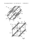
[0045]FIGS. 4 and 5 show reinforcing bodies 11 and 12, which have a three-dimensional shape in the form of a tube (FIG. 4) and a cuboid (FIG. 5), respectively. The reinforcing body 11 shown in FIG. 4 consists of two reinforcing rods 2a bent in the shape of a circle, which are connected to one another by six reinforcing rods 2b running parallel to one another and which are each fixed in the inventive manner to the inner circumference of the circular reinforcing rods 2a at a right angle. In contrast, the reinforcing body 12 shown in FIG. 5 consists of two substantially quadratic reinforcing rods 2a, which are connected to each other by four reinforcing rods 2b running parallel to one another and which are each fixed likewise in the inventive manner to the inside of the four corners of the quadratic reinforcing rods 2a at a right angle.
[0046]In the case of these two reinforcing bodies 11 and 12 also, connecting agents 5 each comprise connection fibers 6 that are embedded in a plastic matrix 7 and wound about reinforcing rods 2a and 2b several times at the respective connecting points 4. The highly stable reinforcing bodies 11 and 12 thus obtained, which are totally insensitive to corrosion, can be used advantageously as pile reinforcements.
[0047]The present invention is not limited, of course, to the embodiment presented here. For example, reinforcing bodies 1, 10, 11 and 12 can vary in the quantity and/or shape and/or size and/or orientation of the reinforcing rods. Fibers and/or plastics made of other materials can also be used. Connection fibers 6, likewise, can be arranged differently. Furthermore, different kinds of reinforcing rods, particularly reinforcing rods of different size and/or shape, can be joined together to form a reinforcing body.
Claims:
1. A reinforcing body (1) for buildings, in particular for buildings made
of concrete, said reinforcing body comprising a plurality of reinforcing
rods (2a, 2b) which are connected together by connecting agents (5) at
connecting points (4) and which are made of fiber-reinforced plastic,
said connecting agents (5) comprising connection fibers (6) which are
embedded in a plastic matrix (7),characterized in that the connection
fibers (6) are wound several times about the reinforcing rods (2a, 2b) at
the connecting points (4) in such a way that, when a tensile or
compressive stress acts transversally to the longitudinal axis of a first
reinforcing rod (2a, 2b) in the longitudinal direction of a second
reinforcing rod (2b, 2a), a connecting force S which satisfies the
equation S>0.3*AS*RB is achieved for a single connection
point (4), where AS describes the cross-sectional area of the second
reinforcing rod (2b, 2a) and RB describes the permissible working
stress of the second reinforcing rod (2b, 2a).
2. The reinforcing body of claim 1, characterized in that the connection fibers (6) are wound in different directions about a connection point (4).
3. The reinforcing body of claim 1, characterized in that the connection fibers (6) at a reinforcing rod (2a, 2b) or at both reinforcing rods (2a, 2b) each intersect at least one point.
4. The reinforcing body of claim 1, characterized in that the connection fibers (6) include glass fibers and/or aramide fibers and/or carbon fibers.
5. The reinforcing body of claim 1, characterized in that the connection fibers (6) and/or the plastic in the plastic matrix (7) at the connecting points (4) consist of the same material as the fibers and/or plastic in the reinforcing rods (2a, 2b).
6. The reinforcing body of claim 1, characterized in that the reinforcing rods (2a, 2b) have external profiling which is specifically embodied as a threaded profile or preferably in the form of a screw thread.
7. The reinforcing body of claim 1, characterized in that the reinforcing rods (2a, 2b) are arranged at least substantially perpendicular to one another.
8. The reinforcing body of claim 1, characterized in that the reinforcing rods (2a, 2b) are arranged at least substantially two-dimensionally in the form of a mat (1, 10).
9. The reinforcing body of claim 8, characterized in that all the reinforcing rods (2a, 2b) extend in a straight line, wherein a first group of reinforcing rods (2a) extends in a first plane (3a) and wherein a second group of reinforcing rods (2b) extends in a second plane (3b) running parallel to the first plane (3a).
10. The reinforcing body of claim 1, characterized in that the reinforcing rods (2a, 2b) form a three-dimensional reinforcing body (11, 12), in particular a reinforcing pile (11) or a reinforcing cage (12).
11. The reinforcing body of claim 10, characterized in that at least individual reinforcing rods (2a, 2b) are curved in sections thereof or throughout.
12. The reinforcing body of claim 11, characterized in that a plurality of reinforcing rods (2a) are embodied in circular shape and are connected on the inside and/or the outside to a plurality of reinforcing rods (2b) extending at least approximately in a straight line to form a tubular reinforcing body (11).
13. The reinforcing body of claim 11, characterized in that a plurality of reinforcing rods (2a) are bent at an angle at least in sections thereof and are embodied in the shape of a square and are connected on the inside and/or on the outside to a plurality of reinforcing rods (2b) extending at least approximately in a straight line to form a cuboidal reinforcing body (12).
14. The reinforcing body of claim 1, characterized in that the plastic matrix (7) is fully hardened with the connection fibers (6) embedded therein.
15. The reinforcing body according to claim 1, characterized in that said reinforcing body is embodied as a prepreg, the plastic matrix (7) with the connection fibers (6) embedded therein being pre-hardened to a certain degree such that a certain degree of mobility is provided at the connecting points (4), wherein said plastic matrix (7) can be fully hardened by the application of heat.
Description:
[0001]The present invention relates to a reinforcing body for structures,
according to the preamble of claim 1, preferably for structures made of
concrete or of other hydraulically setting materials, which may also be
mixed with other materials, for example with ground materials. The
reinforcing body comprises a plurality of reinforcing rods each
consisting of fiber-reinforced plastic and connected to one another at
connecting points by connecting agents. The individual reinforcing rods
can be of any length and cross-sectional shape, and have end portions of
any shape. The reinforcing rods preferably have a round, in particular at
least approximately circular cross-section and an axial extension that is
at least substantially straight.
[0002]The use of reinforcing bodies is generally known. They are used to increase mechanical strength, in particular for increasing the tensile strength of concrete structures. Concrete is a principal component of many structures, for example of buildings or bridges. However, in order to withstand the stresses that arise during use, it is essential that reinforcing struts, especially reinforcing struts that transfer tensile forces, be embedded as reinforcement in the concrete. Steel reinforcing rods and reinforcing bodies have proved over many years to provide suitable reinforcement of concrete buildings.
[0003]However, steel reinforcements can corrode in situations where the working conditions are particularly tough, especially in damp or chemically aggressive environments. Corrosion of the steel reinforcements leads to a reduction in the adhesive forces and/or to deterioration in the bedding between steel and concrete, which results in cracks and in flaking of the concrete. Not only does this cause an unaesthetic appearance of the buildings affected, but the corrosion of the steel reinforcements can lead above all to weakening and ultimately even to final collapse of the structure, thus signifying a major hazard. Due to the damage caused to structures by corrosion, substantial levels of repair and maintenance expense are necessary in order to avoid any further risks.
[0004]Reinforcement with non-corroding or corrosion-resistant reinforcing struts, for example with reinforcing struts or reinforcing bodies that are galvanized or epoxy-coated or made of stainless steel, are known as a means of preventing corrosion-related problems. However, such reinforcing bodies can only be used to a limited extent in certain environmental conditions, for example where chlorine is present in high concentrations. In addition, they involve very high costs, which has hitherto opposed any comprehensive use.
[0005]Furthermore, there are also detrimental impacts on the environment. Since the aforementioned corrosion-protected reinforcing bodies are too expensive, it is recommended that concrete be applied with a thickness of between 75 mm and 120 mm to conventional steel reinforcements in order to cover the steel reinforcing struts sufficiently and in this way to try and prevent them from corroding. Non-renewable natural resources are severely stressed due to the large amount of concrete involved. In addition, unnecessarily large amounts of CO2 are emitted due to the increased production of cement.
[0006]For this reason, the use of reinforcing bodies made of fiber-reinforced plastic, also referred to internationally as "FRP-rebars" ("FRP" being short for "fiber reinforced plastic"), is proposed as a substitute for corrodible steel reinforcements. Such FRP reinforcing bodies are resistant to corrosion and relatively inexpensive, so the aforementioned problems with corrosion can be combated permanently and efficaciously at low cost.
[0007]Fiber-reinforced plastics are composite fiber materials in which the plastic is combined with fibers made of a different material in order to obtain synergy effects and properties that are improved in the desired direction, especially to obtain mechanically improved properties. The fibers used can be glass fibers, for example, which are preferably embedded in the plastic with "unidirectional" fiber orientation in the longitudinal direction of a rod profile. A plurality of fibers aligned parallel to one another and which can have a diameter of between 10 and 30 μm, for example, is thus surrounded by a matrix of plastic resin. The fibers give the composite material its high strength in the longitudinal direction, while the resin matrix serves to fix the fibers in position and simultaneously to protect them against damaging influences.
[0008]In addition to individual reinforcing rods, reinforcing bodies of the kind initially specified and made of fiber-reinforced plastics, in particular, are also known. The connecting agents used to connect the individual plastic rods to one another are often wires, however, particularly conventional tying wires, which in turn are prone to corrosion and can lead to the aforementioned problems. In addition, these wire connections are only a temporary form of securing during transport and assembly, whereas after the concrete has hardened they can no longer make any significant contribution to increasing the tensile and shearing forces of the concrete body. Such reinforcing bodies comprising reinforcing rods connected by wires are known, for example, from document WO 01/26974 A2.
[0009]Cable ties made of plastic, known from the field of electrical installation, are also used for connecting the individual rods. By this means, however, as with the use of wire, only an extremely limited strength can be achieved, and the individual reinforcing rods are still always moved relatively easily in relation to one another. These connecting agents merely result, likewise, in reinforcing bodies which do not optimally increase the load-bearing capacity of the concrete body.
[0010]It is also known to intermesh single reinforcing rods made of fiber-reinforced plastic, but this involves considerable production complexity and correspondingly high costs. In the case of intermeshing, it is also necessary to deform at least individual reinforcing rods, with the result that this type of connection cannot be used in the case of fully hardened reinforcing rods.
[0011]A planar lattice fabric of the kind initially specified, and which can also be used as a reinforcing body, is known from document EP 0 387 968 A1 and from the associated German document DE 690 02 071 T2, in which the connecting agents comprise a warp yarn that is woven as a connection fiber into a plastic matrix. However, the connection fibers in this leno fabric, with a very small weft bending index of maximum 0.03, are curved to only a very small extent, with the result that they run almost in a straight line, substantially parallel to a reinforcing rod, and at the connecting points contact the transversely running reinforcing rods merely from one side over a highly limited circumferential portion. This type of interweaving or intermeshing can only result, therefore, in a reinforcing body which has only relatively low strength and which is thus unable to provide optimal support for a concrete building.
[0012]The object of the present invention is therefore to provide a reinforcing body of the kind initially specified and of simple design, in which the individual reinforcing rods are joined together in a simple and efficient manner such that a very high strength is achieved while simultaneously enabling inexpensive production.
[0013]This object is achieved according to the invention by a reinforcing body according to claim 1. Advantageous configurations and developments of the invention are derived from the dependent claims.
[0014]An important aspect of the inventive solution is that the connection fibers embedded in a plastic matrix are wound several times about the reinforcing rods at the connecting points.
[0015]The main advantage lies in the fact that, in a surprisingly simple manner, a high-strength, in particular undisplacable and positionally stable connection of the individual reinforcing rods to one another is obtained, which can be produced with relatively little production effort and therefore at low cost. The reinforcing rods are connected to one another in a particularly strong manner at the connecting points by multiple winding and subsequent hardening, such that a high-strength reinforcing body is obtained that ensures an optimal increase in the mechanical stability of a concrete structure provided therewith. At each individual connecting point, extremely high connecting forces are achieved.
[0016]Complex intermeshing or interweaving of the individual reinforcing rods is not necessary for this purpose, so the reinforcing rods do not need to be deformed, and even fully hardened reinforcing rods can be joined to one another relatively simply and quickly.
[0017]By embedding the connection fibers in a plastic matrix, the reinforcing rods are connected to one another substantially more strongly than is possible when using cable ties or wires. The connecting agents used according to the invention are formed for their part by fiber-reinforced plastic, which can have connection fibers of any kind, any length, any diameter and any arrangement.
[0018]No corrodible connecting agents are used here, so flaking of concrete due to corrosion, as well as cracks, damage and destruction of concrete buildings can be reliably prevented, while the weight of the reinforcing bodies is very low in total. This results in substantial savings in respect of maintenance and repair work. It is also possible in this way to relieve stress on natural resources, since concrete can be applied substantially more thinly and in significantly smaller volumes to the structures provided with the inventive reinforcements.
[0019]It is particularly advantageous with the inventive reinforcing body when the connection fibers are wound in different directions and/or with different orientations about each connecting point. The connection fibers are preferably wound about the intersection at a cross-shaped connecting point at an angle of 45° to the left and at an angle of 45° to the right. This enables a particularly stable connection to be obtained.
[0020]According to one preferred embodiment of the invention, the connection fibers each intersect at a connecting point at one point or at two points on one reinforcing rod or on both reinforcing rods, respectively. By means of this type of winding, the strength of the connection can be further increased. Nevertheless, it is equally possible to wind the fibers about the reinforcing rods at the connecting points in such a way that winding about the two reinforcing rods is done without criss-crossing and in a U-shape.
[0021]Furthermore it is particularly advantageous when the connection fibers are wound about the reinforcing rods in such a way that, when a tensile stress or compressive stress acts transversally to the longitudinal axis of a first reinforcing rod in the longitudinal direction of a second reinforcing rod, a connecting force S which satisfies the equation S>0.3*AS*RB is reached for a single connection point, where AS is the cross-sectional area of the second reinforcing rod and RB is the permissible working stress of the second reinforcing rod. In this way, especially when the connections are implemented with textile glass as the connection fiber and epoxy resin as the matrix resin, connecting forces of up to 5000 N can be achieved at a single connecting point with reinforcing rods having a diameter of 6 mm. Such high-strength yet highly compact connections between the reinforcing rods thus fulfill the same requirements as welding together reinforcing bodies made of steel.
[0022]It is particularly advantageous with the inventive reinforcing body when the connection fibers include glass fibers and/or aramide fibers and/or carbon fibers. However, it is also possible to use other fibers, for example silicon carbide fibers or boron fibers. The connection fibers preferably comprise only one and the same kind of fiber.
[0023]It is also favorable when the connection fibers and/or the plastic in the plastic matrix at the connecting points consist of the same material as the fibers or plastic in the reinforcing rods. By this means, the production effort involved can be kept particularly low.
[0024]In order to achieve an optimal hold of the reinforcing body in the surrounding material, it is advantageous when the reinforcing rods have external surface profiling that can preferably be embodied in the form of ribs or a screw profile or a screw thread. However, it is also possible to provide non-uniform profiling, for example surfaces roughened by means of sand grains embedded in the resin, in the form of an outer coating, in order to increase the connecting forces and to improve embedding.
[0025]It is proposed, by way of preference, that the reinforcing rods be arranged at least substantially perpendicular to one another. In this way, the connecting agents can be attached in a particularly simple manner. However, the reinforcing rods can also be arranged in any other orientations and/or at different angles.
[0026]According to one particularly preferred embodiment of the invention, the reinforcing rods are arranged at least substantially two-dimensionally in the form of a mat. The individual reinforcing rods can preferably lie above one another in two planes and in this way form a right-angled lattice, in particular. The inventive reinforcing body can be deployed particularly well in the desired size as a reinforcing mat in flat building elements, for example in ceilings or walls. It is particularly advantageous in such cases when all the reinforcing rods can extend in a straight line, wherein a first group of reinforcing rods extends in a first plane and wherein a second group of reinforcing rods extends in a second plane running parallel to the first plane. Deformation of individual reinforcing rods is not necessary in this case, so even fully hardened reinforcing rods can be connected to one another in a particularly simple and quick manner and with the desired high strength.
[0027]According to an alternative embodiment of the invention, the reinforcing rods can also form a three-dimensional reinforcing body, in particular a reinforcing cage, a reinforcing pile or a lattice with three ribs or four ribs. Additional reinforcing rods running at an angle to the reinforcing rods arranged preferably at right angles can also be provided.
[0028]Particularly versatile deployability of the inventive reinforcing body can be achieved by embodying at least individual reinforcing rods with curving in sections thereof or throughout. The curvatures can also be embodied so narrowly or with such a small bending radius that the reinforcing rods curved in such a manner in sections thereof are bent at an angle.
[0029]To this end, it is proposed that a plurality of reinforcing rods are preferably embodied such that they are completely bent to form a circle, and are connected on the inside and/or the outside to a plurality of reinforcing rods arranged preferably at a right angle thereto and extending at least approximately in a straight line to form a tubular reinforcing body which can be used as a pile reinforcement, for example. It is likewise possible, however, to embody the reinforcing rods running on the inside and/or the outside in a curved shape so that tubular reinforcing bodies with a curved profile are obtained, for example in the form of curved lattices.
[0030]As an alternative, it is proposed that a plurality of reinforcing rods are bent at an angle only in sections thereof and are embodied in the shape of a rectangle, in particular as a square, and are connected on the inside and/or on the outside to a plurality of reinforcing rods preferably arranged at a right angle thereto and extending at least approximately in a straight line to form a cuboidal reinforcing body. It is likewise possible to embody the reinforcing rods running on the inside and/or on the outside in a curved shape so that a reinforcing body with a generally curved profile, in particular in the form of a curved lattice is obtained.
[0031]According to one preferred embodiment of the invention, the reinforcing bodies are prefabricated at the factory in such a way that the plastic matrix is fully hardened with the connection fibers embedded therein. The inventive reinforcing bodies arrive in a totally rigid state at the building site, where they are integrated into the structure or into the concrete. The connections between the reinforcing rods are preferably implemented mechanically using plier-type devices, which are preferably arranged in large numbers in a shared production area and which simultaneously produce a correspondingly large number and preferably all of the connection windings of a reinforcing body.
[0032]According to an alternative embodiment of the invention, the reinforcing body can also be embodied as a prepreg, the plastic matrix with the connection fibers embedded therein being pre-hardened only to a certain degree such that a certain degree of mobility is provided in the connecting points, wherein said plastic matrix can be fully hardened at a later time by the application of heat. The use of prepreg is known per se. A significant advantage consists in the fact that the reinforcing body can be used in particularly flexible ways, and can be shaped to current requirements at the building site and can then be finally fixated by brief heating.
[0033]Further advantages and features of the invention derive from the following description and from the embodiments shown in the drawings, in which
[0034]FIG. 1: shows a plan view of a first reinforcing body according to the invention;
[0035]FIG. 2: shows an enlarged cross-sectional view along the line A-A in FIG. 1;
[0036]FIG. 3: shows a plan view of a variant of a second reinforcing body according to the invention;
[0037]FIG. 4: shows a three-dimensional view of a third reinforcing body according to the invention; and
[0038]FIG. 5: shows a three-dimensional view of a fourth reinforcing body according to the invention.
[0039]The reinforcing body 1 shown in FIGS. 1 and 2 consists of four individual reinforcing rods 2a and 2b, each running in a straight line and arranged at right angles to one another in the manner of a double cross. The two reinforcing rods 2a are positioned parallel to one another in a first plane 3a and the two other reinforcing rods 2b are likewise arranged parallel to one another in a second plane 3b on reinforcing rods 2a. Of course, reinforcing body 1 can also comprise a very much larger number of reinforcing rods 2a and 2b, similar to FIG. 3, so FIG. 1 would then show only a portion of the entire reinforcing body 1.
[0040]Reinforcing rods 2a and 2b, embodied as FRP rebars, so called, each consist of fiber-reinforced plastic, in which glass fibers are embedded in a proportion of approximately 60% to 85% in a matrix of polyester resin. However, aramide fibers or carbon fibers can equally well be embedded in a matrix of epoxy resin or vinylester resin. The reinforcing rods 2a and 2b embodied with substantially circular cross-section are all of the same length, and of the same diameter here; the diameter is preferably in the range from 5 mm to 25 mm, but can also be greater. In order to achieve especially high adhesive forces at the surrounding concrete, the surfaces of reinforcing rods 2a and 2b are lightly profiled with a thread structure. However, depending on the specific application of the reinforcing body to be produced, reinforcing rods 2a and 2b can also be of different diameters and/or of different lengths and shapes.
[0041]The four reinforcing rods 2a and 2b are connected to one another in pairs at the four connecting points 4 by connecting agents 5. According to the invention, connecting agents 5 each comprise connection fibers 6, which are embedded in a plastic matrix 7 and wound several times about reinforcing rods 2a and 2b. The resin 7 is previously applied to the fiber material 6 in such a way that the fibers 6 are wound and applied in the "wet" state. In the connecting agents 5 consisting of fiber-reinforced plastic, glass fibers 6 are surrounded by a matrix 7 of polyester resin. In particular, connecting agents 5 can also produce a material fit after complete hardening of the resin 7.
[0042]Connection fibers 6 are wound here on reinforcing rods 2b at angles of +45° and -45° diagonally to the longitudinal direction of reinforcing rods 2b. At reinforcing rods 2a, connection fibers 6 are guided in such a way that they cross both in front of and behind reinforcing rods 2a (in relation to the plane of the drawing in FIG. 2). By means of this kind of multiple winding of connection fibers 6 in different directions about connecting points 4, a particularly strong connection of reinforcing rods 2a and 2b is obtained after resin matrix 7 has hardened, and hence a highly stable reinforcing body 1.
[0043]The reinforcing body 10 shown in FIG. 3 and likewise substantially two-dimensional in structure consists of eighteen reinforcing rods 2a and 2b which are arranged at right angles to one another and are connected to one another, as a reinforcing mat in the shape of a lattice, at a total of eighty-one connecting points 4. In this case also, reinforcing rods 2a are located in a first plane 3a, on which reinforcing rods 2b are arranged in a second plane 3b.
[0044]As in the previously described example, the inventive connecting agents 5 each comprise connection fibers 6, which are embedded in a plastic matrix 7 and wound several times about reinforcing rods 2a and 2b. In this way, a high-strength connection among the individual reinforcing rods 2a, 2b is obtained, which leads to a stable and light reinforcing body 1 that is totally insensitive to corrosion and which can be used advantageously in concrete ceilings or concrete walls. In particular, reinforcing body 1 can be used on bridges or buildings or in tunnel construction to reinforce concrete or similar construction materials.
[0045]FIGS. 4 and 5 show reinforcing bodies 11 and 12, which have a three-dimensional shape in the form of a tube (FIG. 4) and a cuboid (FIG. 5), respectively. The reinforcing body 11 shown in FIG. 4 consists of two reinforcing rods 2a bent in the shape of a circle, which are connected to one another by six reinforcing rods 2b running parallel to one another and which are each fixed in the inventive manner to the inner circumference of the circular reinforcing rods 2a at a right angle. In contrast, the reinforcing body 12 shown in FIG. 5 consists of two substantially quadratic reinforcing rods 2a, which are connected to each other by four reinforcing rods 2b running parallel to one another and which are each fixed likewise in the inventive manner to the inside of the four corners of the quadratic reinforcing rods 2a at a right angle.
[0046]In the case of these two reinforcing bodies 11 and 12 also, connecting agents 5 each comprise connection fibers 6 that are embedded in a plastic matrix 7 and wound about reinforcing rods 2a and 2b several times at the respective connecting points 4. The highly stable reinforcing bodies 11 and 12 thus obtained, which are totally insensitive to corrosion, can be used advantageously as pile reinforcements.
[0047]The present invention is not limited, of course, to the embodiment presented here. For example, reinforcing bodies 1, 10, 11 and 12 can vary in the quantity and/or shape and/or size and/or orientation of the reinforcing rods. Fibers and/or plastics made of other materials can also be used. Connection fibers 6, likewise, can be arranged differently. Furthermore, different kinds of reinforcing rods, particularly reinforcing rods of different size and/or shape, can be joined together to form a reinforcing body.
User Contributions:
Comment about this patent or add new information about this topic:
Images included with this patent application:
 |  |
 |  |
 |
| Similar patent applications: | |
| Date | Title |
|---|---|
| 2010-02-11 | Splice system for fiber-reinforced polymer rebars |
| 2012-03-08 | Grips for associating concrete reinforcement bars |
| 2011-03-17 | Adapters for the boom arm of an aerial work platform |
| 2009-02-05 | Befestigungsvorrichtung fur glasscheiben und platten |
| 2012-05-31 | Revolving roof for an indoor/outdoor stadium |
| New patent applications in this class: | |
| Date | Title |
|---|---|
| 2012-10-04 | Supporting multiple mats |
| 2012-01-19 | Support element for a reinforcing rod |
| 2011-05-12 | System for attaching reinforcing bars |
| 2009-05-14 | Method and apparatus for positioning reinforcing members within hardened material structures |
| 2009-04-23 | Rebar support assembly |
| New patent applications from these inventors: | |
| Date | Title |
|---|---|
| 2016-01-07 | Anchor head and anchor nut for a tension anchor |
| 2015-07-23 | Method for producing reinforcement elements from fibre-reinforced plastic and reinforcement elements produced using said method |
| 2010-11-25 | Anchor nut made of fibre reinforced plastic |
| 2009-12-03 | Fiber reinforced plastic drilling anchor |
| Top Inventors for class "Static structures (e.g., buildings)" | |
| Rank | Inventor's name |
|---|---|
| 1 | Darko Pervan |
| 2 | Gregory F. Jacobs |
| 3 | Husnu M. Kalkanoglu |
| 4 | Ronald P. Hohmann, Jr. |
| 5 | Mark Cappelle |