Patent application title: RADIO CONTROL TOY
Inventors:
Hiroyuki Nagasu (Tokyo, JP)
Assignees:
TOMY COMPANY, LTD.
IPC8 Class: AA63H3004FI
USPC Class:
446456
Class name: Rolling or tumbling (e.g., wheeled) remotely controlled by radio signal
Publication date: 2009-06-04
Patent application number: 20090142987
trol toy including: a body a motion of which is
controllable; a remote controller for transmitting control signal to the
body; and a card for storing control data with regard to a predetermined
motion of the body, wherein the remote controller includes: a card
reading section for reading the control data from the card; and a
transmitting section for transmitting the control signal corresponding to
the control data read by the card reading section; and the body includes:
a receiving section for receiving the control signal transmitted by the
transmitting section; and a moving section for executing predetermined
motion according to the control signal received by the receiving section.Claims:
1. A radio control toy, comprising:a body a motion of which is
controllable;a remote controller for transmitting control signal to the
body; anda card for storing control data with regard to a predetermined
motion of the body, wherein the remote controller includes:a card reading
section for reading the control data from the card; anda transmitting
section for transmitting the control signal corresponding to the control
data read by the card reading section; and the body includes:a receiving
section for receiving the control signal transmitted by the transmitting
section; anda moving section for executing predetermined motion according
to the control signal received by the receiving section.
2. The radio control toy according to claim 1, wherein:the card stores the control data in a magnetic stripe or in the form of barcode.
3. The radio control toy according to claim 1, wherein:the body includes a wheel for running.
4. The radio control toy according to claim 1, wherein:the moving section includes at least one ofa driving unit for causing the body to run according to the control signal;a light emitting section for emitting light according to the control signal; ora sound producing section for producing sound according to the control signal.
5. The radio control toy according to claim 3, wherein:the moving section includes at least one ofa driving unit for causing the body to run according to the control signal;a light emitting section for emitting light according to the control signal; ora sound producing section for producing sound according to the control signal.
6. The radio control toy according to claim 2, wherein:the body includes a wheel for running.
7. The radio control toy according to claim 2, wherein:the moving section includes at least one ofa driving unit for causing the body to run according to the control signal;a light emitting section for emitting light according to the control signal; ora sound producing section for producing sound according to the control signal.Description:
BACKGROUND OF THE INVENTION
[0001]1. Field of the Invention
[0002]The present invention relates to a radio control toy.
[0003]2. Related Art
[0004]Heretofore, an operation of a transmitter of a remote control toy has been complicated because of needing many buttons or sticks or the like to be operated.
[0005]In the meantime, such transmitters as can read such cards storing setting data is proposed in order to simplify a default setting operations in remote control toy (see, for example, Japanese patent No. 2659392).
[0006]However, the invention disclosed in the Japanese patent No. 2659392 still needs many buttons or sticks to be operated, though a default setting operation has simplified. Therefore, the invention is not better to be adapted to a remote control toy particularly for children's use.
SUMMARY OF THE INVENTION
[0007]The present invention was made to solve such a problem. It is, therefore, a main object of the present invention to provide a remote control toy capable of being operated easily.
[0008]According to an aspect of the present invention, there is provided a remote control toy including: a body a motion of which is controllable; a remote controller for transmitting control signal to the body; and a card for storing control data with regard to a predetermined motion of the body, wherein the remote controller includes: a card reading section for reading the control data from the card; and a transmitting section for transmitting the control signal corresponding to the control data read by the card reading section; and the body includes: a receiving section for receiving the control signal transmitted by the transmitting section; and a moving section for executing predetermined motion according to the control signal received by the receiving section.
[0009]Preferably, the card stores the control data in a magnetic stripe or in the form of barcode.
[0010]Preferably, the body includes a wheel for running.
[0011]Preferably, the moving section includes at least one of a driving unit for causing the body to run according to the control signal; a light emitting section for emitting light according to the control signal; or a sound producing section for producing sound according to the control signal.
[0012]According to an aspect of the present invention, the toy body behaves predetermined motion only by causing the remote controller to read the control data stored in the card. Therefore, the remote control toy can be operated easily without requiring a complicated operation of a remote controller.
BRIEF DESCRIPTION OF THE DRAWINGS
[0013]The above and other objects, advantage and features of the present invention will become more fully understood from the detailed description given hereinbelow and the appended drawings which are given by way of illustration only, and thus are not intended as a definition of the limits of the present invention, and wherein:
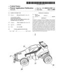
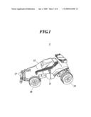
[0014]FIG. 1 is an external view of a toy body according to an embodiment of the present invention;
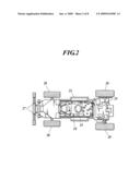
[0015]FIG. 2 is a top view of the toy body of FIG. 1 with a body being removed;
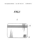
[0016]FIG. 3 is a plan view showing a card according to an embodiment of the present invention;
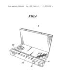
[0017]FIG. 4 is a perspective view showing a remote controller according to an embodiment of the present invention;
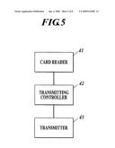
[0018]FIG. 5 is a block diagram showing a control system of the remote controller;
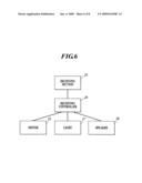
[0019]FIG. 6 is a block diagram showing a control system of the toy body;
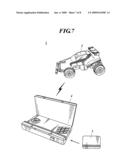
[0020]FIG. 7 is an overall view showing a radio control toy according to an embodiment of the present invention; and
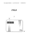
[0021]FIG. 8 is a plan view showing a card according to an embodiment of the present invention.
DETAILED DESCRIPTION OF THE PREFERRED EMBODIMENTS
[0022]In the following, a remote control toy according to an embodiment of the present invention will be described with reference to the attached drawings.
[0023]As shown in FIGS. 1, 3, 4 and 7, a remote control toy 1 according to an embodiment of the present invention includes a toy body 2, a card 3 and a remote controller 4.
[0024]As shown in the external view of FIG. 1, an outer bailey of the toy body 2 includes chassis 21 and a body 22 for surrounding the chassis 21. The chassis 21 and the body 22 are formed of plastic, and formed so that the chassis 21 and the body 22 are fixed with each other by elastically engaging respective engaging sections (not shown) that are formed to correspond with each other. Moreover, the toy body 2 includes front wheels 28 pivotally supported via a shaft for front wheels and rear wheels 29 driven by a motor 25 described below via a shaft for rear wheels.
[0025]As shown in FIG. 2, the toy body 2 includes a housing space on the chassis 21. In this housing space, there are provided a receiving section 23 for receiving a control signal from the remote controller 4, a receiving controller 24 for controlling each part of the toy body 2 according to the received control signal, a motor 25 for driving rear wheels 29 according to a signal from the receiving controller 24, and a speaker 26 for generating horn sound according to the signal from the receiving controller 24. Moreover, lights 27 for emitting light according to a signal from the receiving controller 24 are provided in front part of the chassis 21, and a battery (not shown) for supplying power to the motor 25 or the like is provided at the bottom of the chassis 21. Among the above, the receiving controller 24, the motor 25, the speaker 26 and the lights 27 configure moving section of the toy body 2 according to an embodiment of the present invention. Incidentally, the sound generated by the speaker 26 is not limited to the horn sound but, for example, sound of a siren can be applied.
[0026]As shown in FIG. 3, the card 3 has a magnetic stripe 31 formed on a surface thereof. The magnetic stripe 31 stores control data for causing the toy body 2 to execute any one motion of running, emitting light or producing sounds. Moreover, there are marks provided on the surface of the card 3. The marks include a mark 33 representing running motion, a mark representing light emitting motion (not shown) or a mark 34 representing sound producing motion. Therefore, the card 3 is configured so that types of control data stored therein are discriminable from an external appearance thereof.
[0027]Incidentally, it is only necessary for the card 3 to function as a storage medium. Therefore, substitution such as barcode 32 as shown in FIG. 8 is available alternative to the magnetic stripe 31.
[0028]As shown in the perspective view of FIG. 4, the remote controller 4 is formed to have shape representing computers. The remote controller 4 is equipped with a card reader 41 as a card reading section for reading the control data from the card 3, and a power button 44 at an outside thereof. The card reader 41 is equipped with a slit section 411 for the card 3 to be inserted therein, and a magnetic head 412, which touches the magnetic stripe 31, when the card 3 is inserted in the slit section 411. The card reader 41 can read the control data from the card 3 when the card 3 being manually operated to be moved along the slit section 411 so as to be scanned, with the magnetic stripe 31 and the magnetic head 412 being touched with each other.
[0029]Moreover, as shown in FIG. 5, a transmitting controller 42 and a transmitting section 43 are provided internally in the remote controller 4, wherein the transmitting controller 42 transmits control signal corresponding to the control data from the card reader 41 to the transmitting section 43 and the transmitting section 43 transmits the control signal over the radio to the receiving section 23 of the toy body 2. The control signal is a signal, similar to the control data, for causing the toy body 2 to execute any one motion of running, emitting light or producing sounds. The transmitting controller 42 and the transmitting section 43 are a transmitting section of the remote controller 4 according to an embodiment of the present invention.
[0030]Incidentally, it goes without saying that the card reader 41 of the remote controller 4 should be modified so as to be able to read a barcode i.e. a barcode reader, when, as shown in FIG. 8, the barcode 32 is provided on the card 3 alternative to the magnetic stripe 31, as described above.
[0031]Subsequently, performance of the remote control toy 1 will be described with reference to FIGS. 5 and 6.
[0032]First of all, a player inserts the card 3 into the slit section 411 of the card reader 41 so as to manually operate the card 3 to be moved and scanned along the slit section 411 with the magnetic stripe 31 and the magnetic head 412 being touched with each other. Then, the control data stored in the magnetic stripe 31 is read by the card reader 41. The control data is data for causing the toy body 2 to execute any one motion of running, emitting light or producing sounds.
[0033]The control data read by the card reader 41 is transmitted to the transmitting controller 42. The transmitting controller 42 transmits the control signal to the transmitting section 43 according to content of the control data, wherein the control signal causes the toy body 2 to execute any one motion of running, emitting light or producing sounds. Then, the transmitting section 43 transmits the control signal to the receiving section 23 of the toy body 2.
[0034]The control signal received by the receiving section 23 is transmitted to the receiving controller 24. The receiving controller 24 executes following controls to any one of the motor 25, the speaker 26 and the lights 27, according to the received control signal.
[0035]If the control signal is a signal for causing the toy body 2 to run, the receiving controller 24 controls the motor 25 to cause the rear wheels to be driven. Then, the toy body 2 goes forwardly or backwardly by a predetermined driving force. If the control signal is a signal for causing the toy body 2 to emit light, the receiving controller 24 controls the lights 27 to emit light for awhile. If the control signal is a signal for causing the toy body 2 to produce sounds, the receiving controller 24 controls the speaker 26 to produce horn sound for a while. Incidentally, the running motion of the toy body 2 is not limited to going forwardly or backwardly but includes, for example, circling.
[0036]As described above, a player can easily make the toy body 2 execute motions corresponding to the control data stored in the card 3 only by manually operating the card 3 to be moved and scanned along the slit section 411, without requiring complicated operations. Moreover, the player can enjoy renewed maneuvering feeling not by static motion of traditional stick operation by fingertips, but by dynamic motion of scanning the card 3 swiftly.
[0037]As described above, according to the remote control toy 1, the toy body 2 behaves predetermined motion only by manually operating the card 3 along the card reader 41 of the remote controller 4. Therefore, the remote control toy 1 can be operated easily without requiring a complicated operation of a remote controller.
[0038]Incidentally, the toy body 2 is not limited to such a running toy as described in the present embodiment, but, for example, a robotic walking toy or the like can be applied. Moreover, the toy body 2 may include at least one of the motor 25, the speaker 26 and the lights 27. However, it is needless to say that the moving section such as a motor 25, a speaker 26, lights 27 or the like should be provided corresponding to the control data or the control signal.
[0039]The entire disclosure of Japanese Patent Application No. 2007-312663 filed on Dec. 3, 2007 including description, claims, drawings and summary are incorporated herein by reference in its entirely.
[0040]Although various exemplary embodiments have been shown and described, the invention is not limited to the embodiments shown. Therefore, the scope of the invention is intended to be limited solely by the scope of the claims that follow.
Claims:
1. A radio control toy, comprising:a body a motion of which is
controllable;a remote controller for transmitting control signal to the
body; anda card for storing control data with regard to a predetermined
motion of the body, wherein the remote controller includes:a card reading
section for reading the control data from the card; anda transmitting
section for transmitting the control signal corresponding to the control
data read by the card reading section; and the body includes:a receiving
section for receiving the control signal transmitted by the transmitting
section; anda moving section for executing predetermined motion according
to the control signal received by the receiving section.
2. The radio control toy according to claim 1, wherein:the card stores the control data in a magnetic stripe or in the form of barcode.
3. The radio control toy according to claim 1, wherein:the body includes a wheel for running.
4. The radio control toy according to claim 1, wherein:the moving section includes at least one ofa driving unit for causing the body to run according to the control signal;a light emitting section for emitting light according to the control signal; ora sound producing section for producing sound according to the control signal.
5. The radio control toy according to claim 3, wherein:the moving section includes at least one ofa driving unit for causing the body to run according to the control signal;a light emitting section for emitting light according to the control signal; ora sound producing section for producing sound according to the control signal.
6. The radio control toy according to claim 2, wherein:the body includes a wheel for running.
7. The radio control toy according to claim 2, wherein:the moving section includes at least one ofa driving unit for causing the body to run according to the control signal;a light emitting section for emitting light according to the control signal; ora sound producing section for producing sound according to the control signal.
Description:
BACKGROUND OF THE INVENTION
[0001]1. Field of the Invention
[0002]The present invention relates to a radio control toy.
[0003]2. Related Art
[0004]Heretofore, an operation of a transmitter of a remote control toy has been complicated because of needing many buttons or sticks or the like to be operated.
[0005]In the meantime, such transmitters as can read such cards storing setting data is proposed in order to simplify a default setting operations in remote control toy (see, for example, Japanese patent No. 2659392).
[0006]However, the invention disclosed in the Japanese patent No. 2659392 still needs many buttons or sticks to be operated, though a default setting operation has simplified. Therefore, the invention is not better to be adapted to a remote control toy particularly for children's use.
SUMMARY OF THE INVENTION
[0007]The present invention was made to solve such a problem. It is, therefore, a main object of the present invention to provide a remote control toy capable of being operated easily.
[0008]According to an aspect of the present invention, there is provided a remote control toy including: a body a motion of which is controllable; a remote controller for transmitting control signal to the body; and a card for storing control data with regard to a predetermined motion of the body, wherein the remote controller includes: a card reading section for reading the control data from the card; and a transmitting section for transmitting the control signal corresponding to the control data read by the card reading section; and the body includes: a receiving section for receiving the control signal transmitted by the transmitting section; and a moving section for executing predetermined motion according to the control signal received by the receiving section.
[0009]Preferably, the card stores the control data in a magnetic stripe or in the form of barcode.
[0010]Preferably, the body includes a wheel for running.
[0011]Preferably, the moving section includes at least one of a driving unit for causing the body to run according to the control signal; a light emitting section for emitting light according to the control signal; or a sound producing section for producing sound according to the control signal.
[0012]According to an aspect of the present invention, the toy body behaves predetermined motion only by causing the remote controller to read the control data stored in the card. Therefore, the remote control toy can be operated easily without requiring a complicated operation of a remote controller.
BRIEF DESCRIPTION OF THE DRAWINGS
[0013]The above and other objects, advantage and features of the present invention will become more fully understood from the detailed description given hereinbelow and the appended drawings which are given by way of illustration only, and thus are not intended as a definition of the limits of the present invention, and wherein:
[0014]FIG. 1 is an external view of a toy body according to an embodiment of the present invention;
[0015]FIG. 2 is a top view of the toy body of FIG. 1 with a body being removed;
[0016]FIG. 3 is a plan view showing a card according to an embodiment of the present invention;
[0017]FIG. 4 is a perspective view showing a remote controller according to an embodiment of the present invention;
[0018]FIG. 5 is a block diagram showing a control system of the remote controller;
[0019]FIG. 6 is a block diagram showing a control system of the toy body;
[0020]FIG. 7 is an overall view showing a radio control toy according to an embodiment of the present invention; and
[0021]FIG. 8 is a plan view showing a card according to an embodiment of the present invention.
DETAILED DESCRIPTION OF THE PREFERRED EMBODIMENTS
[0022]In the following, a remote control toy according to an embodiment of the present invention will be described with reference to the attached drawings.
[0023]As shown in FIGS. 1, 3, 4 and 7, a remote control toy 1 according to an embodiment of the present invention includes a toy body 2, a card 3 and a remote controller 4.
[0024]As shown in the external view of FIG. 1, an outer bailey of the toy body 2 includes chassis 21 and a body 22 for surrounding the chassis 21. The chassis 21 and the body 22 are formed of plastic, and formed so that the chassis 21 and the body 22 are fixed with each other by elastically engaging respective engaging sections (not shown) that are formed to correspond with each other. Moreover, the toy body 2 includes front wheels 28 pivotally supported via a shaft for front wheels and rear wheels 29 driven by a motor 25 described below via a shaft for rear wheels.
[0025]As shown in FIG. 2, the toy body 2 includes a housing space on the chassis 21. In this housing space, there are provided a receiving section 23 for receiving a control signal from the remote controller 4, a receiving controller 24 for controlling each part of the toy body 2 according to the received control signal, a motor 25 for driving rear wheels 29 according to a signal from the receiving controller 24, and a speaker 26 for generating horn sound according to the signal from the receiving controller 24. Moreover, lights 27 for emitting light according to a signal from the receiving controller 24 are provided in front part of the chassis 21, and a battery (not shown) for supplying power to the motor 25 or the like is provided at the bottom of the chassis 21. Among the above, the receiving controller 24, the motor 25, the speaker 26 and the lights 27 configure moving section of the toy body 2 according to an embodiment of the present invention. Incidentally, the sound generated by the speaker 26 is not limited to the horn sound but, for example, sound of a siren can be applied.
[0026]As shown in FIG. 3, the card 3 has a magnetic stripe 31 formed on a surface thereof. The magnetic stripe 31 stores control data for causing the toy body 2 to execute any one motion of running, emitting light or producing sounds. Moreover, there are marks provided on the surface of the card 3. The marks include a mark 33 representing running motion, a mark representing light emitting motion (not shown) or a mark 34 representing sound producing motion. Therefore, the card 3 is configured so that types of control data stored therein are discriminable from an external appearance thereof.
[0027]Incidentally, it is only necessary for the card 3 to function as a storage medium. Therefore, substitution such as barcode 32 as shown in FIG. 8 is available alternative to the magnetic stripe 31.
[0028]As shown in the perspective view of FIG. 4, the remote controller 4 is formed to have shape representing computers. The remote controller 4 is equipped with a card reader 41 as a card reading section for reading the control data from the card 3, and a power button 44 at an outside thereof. The card reader 41 is equipped with a slit section 411 for the card 3 to be inserted therein, and a magnetic head 412, which touches the magnetic stripe 31, when the card 3 is inserted in the slit section 411. The card reader 41 can read the control data from the card 3 when the card 3 being manually operated to be moved along the slit section 411 so as to be scanned, with the magnetic stripe 31 and the magnetic head 412 being touched with each other.
[0029]Moreover, as shown in FIG. 5, a transmitting controller 42 and a transmitting section 43 are provided internally in the remote controller 4, wherein the transmitting controller 42 transmits control signal corresponding to the control data from the card reader 41 to the transmitting section 43 and the transmitting section 43 transmits the control signal over the radio to the receiving section 23 of the toy body 2. The control signal is a signal, similar to the control data, for causing the toy body 2 to execute any one motion of running, emitting light or producing sounds. The transmitting controller 42 and the transmitting section 43 are a transmitting section of the remote controller 4 according to an embodiment of the present invention.
[0030]Incidentally, it goes without saying that the card reader 41 of the remote controller 4 should be modified so as to be able to read a barcode i.e. a barcode reader, when, as shown in FIG. 8, the barcode 32 is provided on the card 3 alternative to the magnetic stripe 31, as described above.
[0031]Subsequently, performance of the remote control toy 1 will be described with reference to FIGS. 5 and 6.
[0032]First of all, a player inserts the card 3 into the slit section 411 of the card reader 41 so as to manually operate the card 3 to be moved and scanned along the slit section 411 with the magnetic stripe 31 and the magnetic head 412 being touched with each other. Then, the control data stored in the magnetic stripe 31 is read by the card reader 41. The control data is data for causing the toy body 2 to execute any one motion of running, emitting light or producing sounds.
[0033]The control data read by the card reader 41 is transmitted to the transmitting controller 42. The transmitting controller 42 transmits the control signal to the transmitting section 43 according to content of the control data, wherein the control signal causes the toy body 2 to execute any one motion of running, emitting light or producing sounds. Then, the transmitting section 43 transmits the control signal to the receiving section 23 of the toy body 2.
[0034]The control signal received by the receiving section 23 is transmitted to the receiving controller 24. The receiving controller 24 executes following controls to any one of the motor 25, the speaker 26 and the lights 27, according to the received control signal.
[0035]If the control signal is a signal for causing the toy body 2 to run, the receiving controller 24 controls the motor 25 to cause the rear wheels to be driven. Then, the toy body 2 goes forwardly or backwardly by a predetermined driving force. If the control signal is a signal for causing the toy body 2 to emit light, the receiving controller 24 controls the lights 27 to emit light for awhile. If the control signal is a signal for causing the toy body 2 to produce sounds, the receiving controller 24 controls the speaker 26 to produce horn sound for a while. Incidentally, the running motion of the toy body 2 is not limited to going forwardly or backwardly but includes, for example, circling.
[0036]As described above, a player can easily make the toy body 2 execute motions corresponding to the control data stored in the card 3 only by manually operating the card 3 to be moved and scanned along the slit section 411, without requiring complicated operations. Moreover, the player can enjoy renewed maneuvering feeling not by static motion of traditional stick operation by fingertips, but by dynamic motion of scanning the card 3 swiftly.
[0037]As described above, according to the remote control toy 1, the toy body 2 behaves predetermined motion only by manually operating the card 3 along the card reader 41 of the remote controller 4. Therefore, the remote control toy 1 can be operated easily without requiring a complicated operation of a remote controller.
[0038]Incidentally, the toy body 2 is not limited to such a running toy as described in the present embodiment, but, for example, a robotic walking toy or the like can be applied. Moreover, the toy body 2 may include at least one of the motor 25, the speaker 26 and the lights 27. However, it is needless to say that the moving section such as a motor 25, a speaker 26, lights 27 or the like should be provided corresponding to the control data or the control signal.
[0039]The entire disclosure of Japanese Patent Application No. 2007-312663 filed on Dec. 3, 2007 including description, claims, drawings and summary are incorporated herein by reference in its entirely.
[0040]Although various exemplary embodiments have been shown and described, the invention is not limited to the embodiments shown. Therefore, the scope of the invention is intended to be limited solely by the scope of the claims that follow.
User Contributions:
Comment about this patent or add new information about this topic:
Images included with this patent application:
 |  |
 |  |
 |  |
 |  |
 |
| Similar patent applications: | |
| Date | Title |
|---|---|
| 2013-04-04 | Radio frequency controlled aircraft |
| 2013-04-04 | Entertainment device including a remote controlled magnetic mini-craft |
| 2013-02-14 | Creature construction toy |
| 2013-04-18 | Distributed system of autonomously controlled mobile agents |
| New patent applications in this class: | |
| Date | Title |
|---|---|
| 2016-05-12 | Self-righting model vehicle |
| 2016-02-18 | Transformable toy car |
| 2016-01-21 | On-board audio system for a model vehicle |
| 2016-01-21 | On-board audio system for a model vehicle |
| 2015-05-28 | Autonomous toy capable of tracking and interacting with a source |
| New patent applications from these inventors: | |
| Date | Title |
|---|---|
| 2014-02-20 | Toy system having two play structures and a figurine |
| Top Inventors for class "Amusement devices: toys" | |
| Rank | Inventor's name |
|---|---|
| 1 | Robert H. Mimlitch, Iii |
| 2 | David Anthony Norman |
| 3 | Michael Nuttall |
| 4 | Stacy Lynn O'Connor |
| 5 | Joel Reagan Carter |