Patent application title: BUBBLE-FORMING DEVICE
Inventors:
Ma Lai San (Hong Kong, HK)
IPC8 Class: AA63H3328FI
USPC Class:
446 15
Class name: Amusement devices: toys having means for forming transitory bubble
Publication date: 2009-06-04
Patent application number: 20090142986
ncludes a collapsible/expandable bubble-forming
member (resilient ring, multi-link, or guillotine slides) movable between
open and closed positions. A pump deposits bubble-making solution from a
container to the bubble-forming member so that when expanded, a film
forms across its opening. A blower blows air through a duct toward the
opening to form bubbles. The bubble-forming member is anchored in a
collection tub and includes a top connected to a lift, which is in turn
pivoted to the duct and operably connected to a trigger. The trigger is
slidably mounted on the air duct and configured to actuate the lift. The
trigger also operates a switch that actuates a battery-operated motor to
drive both the blower and the pump. Thus, actuation of the trigger
mechanism causes the bubble-forming member to move from the closed
position to the open position, as well as pumps solution and turns on the
blower.Claims:
1. A bubble-forming device comprising:a collapsible/expandable
bubble-forming member movable between an opening-defining position and a
collapsed position;a bubble-solution depositing system for depositing
bubble solution on the bubble-forming member; anda mechanism for
selectively moving the bubble-forming member between the opening-defining
and collapsed positions.
2. The device of claim 1, including a blower for motivating air toward the bubble-forming member.
3. The device of claim 2, including a motor for operating the blower.
4. The device of claim 2, wherein the depositing system includes a pump and further includes a motor for operating the pump.
5. The device of claim 4, wherein the motor is also connected to and operates the blower.
6. The device of claim 1, wherein the mechanism includes a lift attached to a top of the bubble-forming member.
7. The device of claim 6, including a collection tub holding a bottom of the member in a stationary position.
8. The device of claim 6, wherein the mechanism includes a trigger configured to move the lift and expand the bubble-forming member.
9. The device of claim 1, including a collection tub positioned generally under the bubble-forming member.
10. The device of claim 1, including a blower and a structure that supports the blower and that also forms a duct for directing air toward the opening.
11. The device of claim 10, wherein the mechanism includes a motor operably connected to the depositing system, a power source for the motor, and a trigger that slidably engages the structure for movement between on and off positions for selectively connecting the power source to the motor.
12. The device of claim 11, wherein the mechanism includes a lift pivoted to the structure.
13. The device of claim 12, wherein the lift includes an angled slot, and the trigger has protrusions that slides along the slot for rotating the lift.
14. The device of claim 1, wherein the bubble-forming member is flexible and is made of a resilient material.
15. The device of claim 1, wherein the bubble-forming member includes multiple links pivotally interconnected to form a collapsible ring.
16. The device of claim 15, wherein the multiple links include at least four link members.
17. The device of claim 1, wherein the bubble-forming member includes operably inter-connected adjustably-overlapping guillotine members that form the opening when in a partially-separated condition, but that are collapsible to eliminate the opening.
18. The device of claim 17, wherein the operably inter-connected adjustably-overlapping guillotine members are slidably connected.
19. The device of claim 1, including a housing enclosing and supporting the bubble-solution depositing system and the mechanism for selectively moving the bubble-forming member between the opening-defining and collapsed positions, the housing defining a bubble outlet and operably supporting the bubble-forming member near the bubble outlet.
20. A bubble-forming device comprising:a housing having a front opening;a container coupled to the housing and including an interior that retains bubble solution;a collapsible/expandable bubble-forming member positioned adjacent the front opening, the member being movable from a collapsed position to an opening-defining position and being configured to form a film when expanded to the opening-forming position; anda trigger mechanism coupled to the collapsible bubble-forming member so that actuation of the trigger mechanism causes the collapsible member to move from the collapsed position to the opening-defining position.
21. The device defined in claim 20, including a pumping system including tubing that couples the interior of the container with the collapsible/expandable bubble-forming member.
22. A bubble-forming device comprising:a housing having a front opening;an opening-forming member attached to the housing at a first location, the member being movable between an opening-forming position and a closed position;a pivoting lift pivoted at a first location and connected to the opening forming member at a second location spaced from the first location;a fan and air duct for flowing air toward the front opening; anda trigger operably slidably engaging the air duct for sliding support of the trigger, the trigger and lift including an angled slot and slot-engaging pin that, when the trigger is moved, cause the lift to pivot, thus motivating the opening-forming member to move between the opening-forming and closed positions.
23. A bubble-forming device comprising:a collapsible/expandable bubble-forming member movable between open and closed positions, the member forming an opening when in the open position;a pump positioned to deposit bubble-making solution from a container to the bubble-forming member so that when expanded, a film forms across the opening;a blower and duct positioned to direct air toward the opening to form bubbles;a collection tub positioned under the bubble-forming member;a lift pivoted to the duct;a trigger slidably mounted to the duct and operably engaging the lift to pivot the lift upon actuation of the trigger,the bubble-forming member being anchored in the collection tub and including a top connected to the lift; anda switch operated by movement of the trigger that actuates a battery-operated motor to drive both the blower and the pump; whereby actuation of the trigger causes the bubble-forming member to move from the closed position to the open position, as well as pumps solution and turns on the blower.
24. The device of claim 23, wherein the collapsible/expandable bubble-forming member comprises one of a resilient ring, a multi-link member, and a pair of interconnected guillotine slides.
25. A method of forming bubbles comprising steps of:providing an expandable/collapsible opening-forming member that is movable between an open position defining an opening and a collapsed position;pumping bubble solution onto the opening-forming member;moving the opening-forming member from the collapsed position to the opening position to form a film over an opening defined by the member; andmotivating air toward the opening covered with film to form a stream of bubbles.
26. The method defined in claim 25, including providing an air duct, a trigger and a lift, the lift being operably connected to move the opening-forming member, and the trigger being operably supported by the air duct for movement and operably connected to the lift for operating the lift, and including a step of moving the trigger to operate the lift and in turn move the opening-forming member to the opening position.Description:
FIELD OF THE INVENTION
[0001]The present invention relates to bubble-forming devices, and more particularly to a portable hand-held toy device for automatic generation of a steady stream of bubbles. However, the present invention is not believed to be limited to only toys nor limited to only hand-held devices.
BACKGROUND OF THE INVENTION
[0002]Several toy devices for making bubbles are known. Automated versions of such devices typically include an apertured member forming an opening and a wiper, with one of the member and wiper being movable past the other to create a film of bubble-forming solution across the opening. As air is blown into the film-covered opening, a steady stream of bubbles is formed from the film. However, alternative bubble-forming structures and arrangements are desired with simplified configurations and components that move along shorter paths. Further, alternative bubble-forming structures and arrangements are desired with components that are more durable, more integrated, and more robust and long-lasting.
SUMMARY OF THE PRESENT INVENTION
[0003]In one aspect of the present invention, a bubble-forming device includes a collapsible/expandable bubble-forming member movable between an opening-defining position and a collapsed position, a bubble-solution depositing system for depositing bubble solution on the bubble-forming member, and a mechanism for selectively moving the bubble-forming member between the opening-defining and collapsed positions.
[0004]In another aspect of the present invention, a bubble-forming device includes a housing having a front opening, and a container coupled to the housing and including an interior that retains bubble solution. A collapsible/expandable bubble-forming member is positioned adjacent the front opening, the member being movable from a collapsed position to an opening-defining position. A pumping system includes tubing that couples the interior of the container with the collapsible bubble-forming member, and a trigger mechanism is coupled to the collapsible bubble-forming member so that actuation of the trigger mechanism causes the collapsible member to move from the collapsed position to the opening-defining position.
[0005]In another aspect of the present invention, a bubble-forming device includes a housing having a front opening, an opening-forming member attached to the housing at a first location, the member being movable between an opening-forming position and a closed position, and a pivoting lift pivoted at a first location and connected to the moving part at a second location spaced from the first location. A fan and air duct are provided for flowing air toward the front opening, and a trigger operably slidably engages the air duct for sliding support of the trigger. The trigger and lift include an angled slot and slot-engaging pin that, when the trigger is moved, cause the lift to pivot, thus motivating the opening-forming member to move between the opening-forming and closed positions.
[0006]In another aspect of the present invention, a bubble-forming device includes a collapsible/expandable bubble-forming member movable between open and closed positions, the member forming an opening when in the open position. A pump is positioned to deposit bubble-making solution from a container to the bubble-forming member so that when expanded, a film forms across the opening. A blower and duct are positioned to direct air toward the opening to form bubbles. A collection tub is under the bubble-forming member. A lift is pivoted to the duct, and a trigger is slidably mounted to the air duct and positioned to operably engage the lift to pivot the lift upon actuation of the trigger. The bubble-forming member is anchored in the collection tub and includes a top connected to the lift. A switch operated by movement of the trigger is connected to actuate a battery-operated motor to drive both the blower and the pump. By this arrangement, actuation of the trigger causes the bubble-forming member to move from the closed position to the open position, as well as pumps solution and turns on the blower.
[0007]In a narrower form, the collapsible/expandable bubble-forming member comprises one of a resilient ring, a multi-link member, and a pair of interconnected guillotine slides.
[0008]In another aspect of the present invention, a method of forming bubbles comprises steps of providing an expandable/collapsible opening-forming member that is movable between an open position defining an opening and a collapsed position, and pumping bubble solution onto the opening-forming member. The method further includes moving the opening-forming member from the collapsed position to the open position to form a film over the opening defined by the member, and motivating air toward the film-covered opening to form a stream of bubbles.
[0009]An object of the present invention is to provide a collapsible/expandable bubble-forming member movable between an open position defining an opening for making bubbles and a closed position for initially receiving bubble solution so that a film of bubble solution forms across the opening when the bubble-forming member is expanded.
[0010]An object of the present invention is to provide a simplified bubble-forming member by making the member collapsible and expandable.
[0011]These and other aspects, objects, and features of the present invention will be understood and appreciated by those skilled in the art upon studying the following specification, claims, and appended drawings.
BRIEF DESCRIPTION OF DRAWINGS
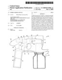
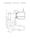
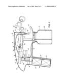
[0012]FIGS. 1-2 are side views of the present bubble-making device, FIG. 1 showing general positions and locations of major components (in dashed lines since a side of the housing is present) and FIG. 2 being a side cross section so that actual components are visible.
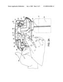
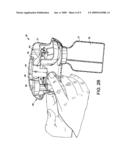
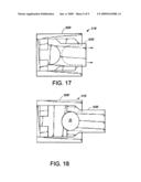
[0013]FIGS. 2A and 2B are perspective views similar to FIG. 2, but with FIG. 2A showing the trigger pulled and the collapsible/expandable member expanded to form the bubble-making opening, and FIG. 2B showing the trigger released and the collapsible/expandable member collapsed.
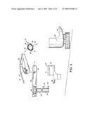
[0014]FIG. 3 is an exploded side view of several major components of the device of FIG. 2 (minus the housing).
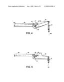
[0015]FIGS. 4-5 are side views showing interaction of the collapsible/expandable bubble-forming member, the blower and duct structure, and the lift, FIG. 4 showing the member in the expanded opening-forming position and FIG. 5 showing the member in the collapsed position.
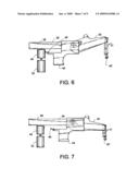
[0016]FIGS. 6-7 are side views similar to FIGS. 4-5 but showing interaction of the collapsible/expandable bubble-forming member, the blower and duct structure, the lift, the trigger, the motor and the pump, FIG. 6 showing the trigger pulled (i.e. in the "on" position) and the member in the expanded opening-forming position and FIG. 7 showing the trigger released (i.e. in the "off" position) and the member in the collapsed position.
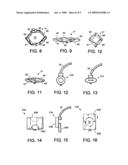
[0017]FIGS. 8-9 are front views showing the six-link collapsible/expandable bubble-forming member, FIG. 8 being expanded to form an opening and FIG. 9 being collapsed.
[0018]FIGS. 10-11 are front views showing a modified four-link version of the collapsible/expandable bubble-forming member, FIG. 10 being expanded to form an opening and FIG. 11 being collapsed.
[0019]FIGS. 12-13 are front views showing a modified flexible/resilient version of the collapsible/expandable bubble-forming member, FIG. 12 being expanded to form an opening and FIG. 13 being collapsed.
[0020]FIGS. 14-16 are front, side, and front views showing a guillotine-type collapsible/expandable bubble-forming member, FIG. 14 being closed and collapsed, and FIGS. 15-16 being expanded to form an opening.
[0021]FIGS. 17-18 are front views showing a second guillotine-type collapsible/expandable bubble-forming member, the components being slidably interconnected and including stops for limiting sliding movement, FIG. 17 being closed and collapsed, and FIG. 18 being expanded to form an opening.
DETAILED DESCRIPTION OF PREFERRED EMBODIMENTS
[0022]For purposes of description herein, the terms "upper," "lower," "top," "bottom," "right," "left," "rear," "front," "vertical," "horizontal," and derivatives thereof shall relate to the invention as oriented in FIG. 1, the "front" being toward the right, such as if a person was standing behind the bubble-making gun 30 (called a "device" herein) and holding the device in a forward-pointed direction. However, it is to be understood that the invention may assume various alternative orientations, except where expressly specified to the contrary. It is also to be understood that the specific devices and processes illustrated in the attached drawings, and described in the following specification, are simply exemplary embodiments of the inventive concepts defined in the appended claims. Hence, specific dimensions and other physical characteristics relating to the embodiments disclosed herein are not to be considered as limiting, unless the claims expressly state and require otherwise.
[0023]In the illustrated example, a bubble-forming device 30 (FIGS. 1-2) includes a collapsible/expandable bubble-forming member 31 movable between an open position (FIG. 2A) defining an opening 32 and a closed position (FIG. 2B) for initially receiving bubble solution 36 so that a film of bubble solution forms across the opening 32 when the bubble-forming member 31 is expanded. The illustrated bubble-forming member 31 comprises a multi-link arrangement (FIGS. 8-9.) However, it is contemplated that the bubble-forming member 31 can be made in different ways, such as with a resilient ring 31A (FIGS. 12-13) and/or slidably-interconnected guillotine members 31B (FIGS. 14-16).
[0024]The illustrated device 30 (FIG. 2) includes a bubble-solution depositing system comprising a pump 33, a suction line 34 and a supply line 35 for drawing bubble-making solution 36 from a container 37 and depositing the solution 36 onto the bubble-forming member 31 so that when expanded, a film of the solution 36 is formed across the opening 32 of the collapsible/expandable bubble-forming member 31. The device 30 includes a trigger 44 (discussed in more detail below) that, when activated, forces a blower 38 to blow air through a duct 39 and through a longitudinally-open center of the lift 42 toward the opening 32 to form the bubbles 36''. Once the solution 36 covering the opening 32 of the collapsible/expandable bubble-forming member 31 has been exhausted such that no more bubbles 36'' are being formed, the trigger 44 is deactivated to allow the collapsible/expandable bubble-forming member 31 to move to the closed position so that the film of bubble solution can once again form across the opening 32 when the bubble-forming member 31 is expanded.
[0025]In the illustrated example, the bubble-forming member 31 includes a bottom anchored to a collection tub 40 and a top connected to a lift 42. The lift 42 is in turn pivoted to the duct 39 at location 43 and operably connected to the trigger 44. The trigger 44 is slidably mounted on the air duct 39 and includes a pin 46 operably engaging an angled slot 47 in the sidewalls of the lift 42 to actuate the lift 42 when the trigger 44 is operated. The angle of the slot 47 causes the lift 42 to be raised when the trigger 44 is pulled (thus opening the member 31), and to be lowered when the trigger 44 is released (thus closing the member 31). The trigger 44 also operates a switch 48 that actuates a battery-operated motor 49 to drive both the blower 38 and the pump 33. Thus, actuation of the trigger 44 causes the bubble-forming member 31 to move from the closed position to the open position, as well as pumps solution 36 and turns on the blower 38. The pins 46 and slots 47 are arranged to assure that a film of bubble-making solution is put onto the member 31 while the member 31 is sufficiently closed to reliably make a film as it is opened.
[0026]As noted above, the illustrated pumping system includes the pump 33, the suction line 34 and the supply line 35 for depositing bubble-making solution 36 from the container 37 onto the bubble-forming member 31. The pump 33 can be a battery operated mini pump, which pumps are well known to those skilled in the art. The illustrated pump 33 includes an axle drive that extends upwardly and is connected to the main shaft of the motor 49. The suction line 34 extends from a location near a bottom of the container 37 to an inlet to the pump 33, and the supply line 35 extends from a pump outlet to a location near a top of the bubble-forming member 31, such that bubble solution 36 flows onto the member 31 for forming the film across the opening of member 31. It is contemplated that a scope of the present invention includes using any pump to force the solution 36 from the container 37 onto the bubble-forming member 31.
[0027]The illustrated blower 38 is arranged to blow air through the duct 39 and longitudinally through an open center of the lift 42 toward the opening 32 to form the bubbles 36''. Blowers for bubble guns are generally known in the art. However, it is contemplated that the blower 38 could include top and bottom structural halves joined together to form a fan housing that captures a rotatable fan. The rotatable fan includes an axle drive that extends downwardly and is connected to the main shaft of the motor 49. However, any blower 38 could be used in the device 30 of the present invention. The top and bottom structural halves also join together to form the hollow duct 39 that directs air from the fan toward the opening 32. The duct 39 forms the pivot 43 and also provides top and side surfaces forming a linear bearing for slidably supporting the trigger 44.
[0028]In the illustrated example, the housing 50 comprises opposing half molded shells of polymeric material attached together (such as by one side including apertured bosses and the other including protrusions fitting into the bosses) to form a pistol-shaped enclosure. The enclosure optionally includes an air inlet 51 for the blower 38 and a bubble outlet opening 52 positioned near the member 31. The housing 50 includes brackets and integrally-molded attachment structure as needed to structurally support the several components of the present device 30 in their respective positions. The housing 50 includes a lower portion 53 that defines a hand grip with undulations for comfortably supporting a user's hand and fingers. Inside the hand grip is the internal space 54 that is adapted to support batteries 55. A removable snap-attach cover is attached to a bottom of the grip to provide access for removing/replacing the batteries. The internal space includes wiring 56 and 56', one of which electrically connects the batteries 55 to the motor 49 and another of which extends to the switch 48. The switch 48 is located on the trigger 44 so that when the trigger 44 is operated, the switch 48 is closed and the motor 49 given power to operate the pump 33 and the blower 38. As noted above, the motor 49 is positioned between the blower 38 and the pump 33 and includes a main shaft that drives both. It is further contemplated that the housing 50 could includes an internally threaded opening surrounding the collection tub 40 for receiving a threaded top opening of a typically bottle or container of bubble solution. While one configuration of the device 30 is illustrated in the drawings, it is contemplated that the device 30 could have any configuration as a gun or other device for ejecting a stream of bubbles.
[0029]The illustrated lift 42 is pivoted to duct 39 at the pivot 43 and is attached to a top of the bubble-forming member 31 as follows. The duct 39 includes opposing "+" shaped projections. The lift 42 includes a body with opposing side flanges that straddle the duct 39. The opposing side flanges include holes that receive and rotatably engage the "+" shaped projections, thus providing pivotal support to the lift 42. The side flanges further include the slots 47 which extend at an upward angle and that are generally horizontally aligned with the center axis defined by the "+" shaped projections.
[0030]In the illustrated example, the trigger 44 includes side flanges joined by a transverse flange that slides along a top of the duct 39, such that the trigger 44 is slidably mounted to the duct 39 for sliding movement toward (and away from) the motor 49 (which is at a rear of the device 30) and away from (and toward) the lift 42 (which is at a front of the device 30). The side flanges include the pins 46, which are positioned forward of the projections. As the trigger 44 is operated and moved rearward toward its "on" position, the pins 46 are moved horizontally toward the "+" shaped projections. Since the slots 47 extend at an angle, this causes the lift 42 to pivot from its horizontal "off" position (FIG. 2B) about the "+" shaped projections toward an upwardly angled "on" position (FIG. 2A). This causes the bubble-forming member 31 to be expanded upwardly and to form the opening 32. As the trigger 44 is operated (i.e., moved to its "on" position), the switch 48 contacts a metal casing of the motor 49. Thus, electrical power is communicated to the motor 49 from the batteries 55. A spring 55' biases the trigger 44 toward an "off" position, which causes the switch 48 to disconnect power from the motor 49 once the trigger 44 is released. This turns off the motor 49 and also causes the lift 42 to drop (which causes the bubble-forming member 31 to close). It is contemplated that the pin and slot and switch can be arranged to turn the motor on and to pump bubble-making solution before the member 31 is opened "too far". However, it is also contemplated that the member 31 can be configured to allow the bubble-making solution to form a film across its opening even when the bubble-making solution is pumped after the member 31 is relatively open. Further, it is contemplated that the trigger 44 could be used to open the collapsible/expandable bubble-forming member 31 in any manner. For example, the trigger 44 could include any linkage configured to open the collapsible/expandable bubble-forming member 31 by lifting the top of the collapsible/expandable bubble-forming member 31 with the bottom of the collapsible/expandable bubble-forming member 31 being fixed in position. Alternatively, the top of the collapsible/expandable bubble-forming member 31 could be fixed in position and the collapsible/expandable bubble-forming member 31 could be opened by moving the bottom of the collapsible/expandable bubble-forming member 31 away from the top of the collapsible/expandable bubble-forming member 31. Furthermore, it is contemplated that the collapsible/expandable bubble-forming member 31 could open and close in any direction.
[0031]The illustrated collection tub 40 forms an upwardly-open collection tray generally under the bubble-forming member 31. An inverted U-shaped stand 40' extends from a center of the tub 40 upwardly. A bottom of the bubble-forming member 31 is attached to the stand 40'. A drain hole (or tube) in the tub 40 extends from the tub 40 back toward the container for draining bubble-solution 36 back to the container 37. The housing 37 includes a threaded portion shaped to thread onto a bottle of bubble-making solution 36. The bottle itself can be provided with the device 30, or the threads can be shaped to accept a known existing bottle of bubble-making solution.
[0032]In the illustrated example, the illustrated bubble-forming member 31 (FIGS. 2A, 2B, 3, 8, 9) includes multiple links interconnected to form a ring. The six-link version of the member 31 offers the advantage of a short movement due to overlap of links when closed and due to six-link arrangement which causes sides of the ring to move inward as top and bottom members move apart, thus reducing total movement required for creating a desired opening size. The illustrated links of member 31 (FIG. 8) include six links 60-65 (more or less links could be used if desired), with links 61, 63, 65 being double-plate links and with links 60, 62, 64 being single plate links. Top and bottom links 60 and 63 extend horizontally, with bottom link 60 being held stationary by the inverted U-shaped stand and with top link 63 being movable (i.e., attached to a front end of the lift 42). Both links 60 and 63 are maintained in a continuous generally-horizontal orientation. The links 61-62 are attached to one end of the top and bottom links 60 and 63 to form a chain on one side, and the links 64-65 are attached to another end of the top and bottom links 60 and 63 to form a second chain on the other side. The links 60-65 are pivotally connected end to end to form a ring. The double-plate links 61, 63, and 65 form a space between the double-plates, thus allowing some overlap of a majority of the edges of the links 60-65 when in the collapsed position. This helps assure a complete coating of the bubble solution 36, such that the film properly forms when the member 31 is expanded to form the opening 32 (FIG. 8).
[0033]It is contemplated that the collapsible/expandable bubble-forming member 31 can be formed by other means than links. For example, FIGS. 10-11 illustrate a four-link bubble-forming member 31' with links 61', 62', 64', and 65' forming collapsible side-linkages. A collapsible/expandable bubble-forming member 31A (FIGS. 12-13) is illustrated that is made of a resilient material, such as rubber, foam or flexible plastic. The member 31A is attached at top and bottom locations similar to member 31 discussed above. The member 31A can be substituted into the device 30 in place of member 31 without otherwise changing the device 30.
[0034]The collapsible/expandable bubble-forming member 31B (FIGS. 14-16) can also be substituted for member 31. Member 31B includes sliding guillotine members 60B and 63B that move together to collapse the opening (FIG. 14), and that move apart (FIG. 16) to form the opening. FIGS. 17-18 disclose a second guillotine-type member 31B' with slidably connected members 60B' and 63B'. The connected members 60B' and 63B' form side tracks that help maintain their mutual alignment, and also include stops that prevent overtravel when moved to the open position (FIG. 18).
[0035]It is also contemplated that a scope of the present invention includes eliminating the blower and/or replacing the blower 38 with an alternative system for motivating air. For example, bellows could be used. Alternatively, a person using the device could provide air flow through the duct as needed or desired by flowing into a rear end of the duct.
[0036]It is to be understood that variations and modifications can be made on the aforementioned structure without departing from the concepts of the present invention, and further it is to be understood that such concepts are intended to be covered by the following claims unless these claims by their language expressly state otherwise.
Claims:
1. A bubble-forming device comprising:a collapsible/expandable
bubble-forming member movable between an opening-defining position and a
collapsed position;a bubble-solution depositing system for depositing
bubble solution on the bubble-forming member; anda mechanism for
selectively moving the bubble-forming member between the opening-defining
and collapsed positions.
2. The device of claim 1, including a blower for motivating air toward the bubble-forming member.
3. The device of claim 2, including a motor for operating the blower.
4. The device of claim 2, wherein the depositing system includes a pump and further includes a motor for operating the pump.
5. The device of claim 4, wherein the motor is also connected to and operates the blower.
6. The device of claim 1, wherein the mechanism includes a lift attached to a top of the bubble-forming member.
7. The device of claim 6, including a collection tub holding a bottom of the member in a stationary position.
8. The device of claim 6, wherein the mechanism includes a trigger configured to move the lift and expand the bubble-forming member.
9. The device of claim 1, including a collection tub positioned generally under the bubble-forming member.
10. The device of claim 1, including a blower and a structure that supports the blower and that also forms a duct for directing air toward the opening.
11. The device of claim 10, wherein the mechanism includes a motor operably connected to the depositing system, a power source for the motor, and a trigger that slidably engages the structure for movement between on and off positions for selectively connecting the power source to the motor.
12. The device of claim 11, wherein the mechanism includes a lift pivoted to the structure.
13. The device of claim 12, wherein the lift includes an angled slot, and the trigger has protrusions that slides along the slot for rotating the lift.
14. The device of claim 1, wherein the bubble-forming member is flexible and is made of a resilient material.
15. The device of claim 1, wherein the bubble-forming member includes multiple links pivotally interconnected to form a collapsible ring.
16. The device of claim 15, wherein the multiple links include at least four link members.
17. The device of claim 1, wherein the bubble-forming member includes operably inter-connected adjustably-overlapping guillotine members that form the opening when in a partially-separated condition, but that are collapsible to eliminate the opening.
18. The device of claim 17, wherein the operably inter-connected adjustably-overlapping guillotine members are slidably connected.
19. The device of claim 1, including a housing enclosing and supporting the bubble-solution depositing system and the mechanism for selectively moving the bubble-forming member between the opening-defining and collapsed positions, the housing defining a bubble outlet and operably supporting the bubble-forming member near the bubble outlet.
20. A bubble-forming device comprising:a housing having a front opening;a container coupled to the housing and including an interior that retains bubble solution;a collapsible/expandable bubble-forming member positioned adjacent the front opening, the member being movable from a collapsed position to an opening-defining position and being configured to form a film when expanded to the opening-forming position; anda trigger mechanism coupled to the collapsible bubble-forming member so that actuation of the trigger mechanism causes the collapsible member to move from the collapsed position to the opening-defining position.
21. The device defined in claim 20, including a pumping system including tubing that couples the interior of the container with the collapsible/expandable bubble-forming member.
22. A bubble-forming device comprising:a housing having a front opening;an opening-forming member attached to the housing at a first location, the member being movable between an opening-forming position and a closed position;a pivoting lift pivoted at a first location and connected to the opening forming member at a second location spaced from the first location;a fan and air duct for flowing air toward the front opening; anda trigger operably slidably engaging the air duct for sliding support of the trigger, the trigger and lift including an angled slot and slot-engaging pin that, when the trigger is moved, cause the lift to pivot, thus motivating the opening-forming member to move between the opening-forming and closed positions.
23. A bubble-forming device comprising:a collapsible/expandable bubble-forming member movable between open and closed positions, the member forming an opening when in the open position;a pump positioned to deposit bubble-making solution from a container to the bubble-forming member so that when expanded, a film forms across the opening;a blower and duct positioned to direct air toward the opening to form bubbles;a collection tub positioned under the bubble-forming member;a lift pivoted to the duct;a trigger slidably mounted to the duct and operably engaging the lift to pivot the lift upon actuation of the trigger,the bubble-forming member being anchored in the collection tub and including a top connected to the lift; anda switch operated by movement of the trigger that actuates a battery-operated motor to drive both the blower and the pump; whereby actuation of the trigger causes the bubble-forming member to move from the closed position to the open position, as well as pumps solution and turns on the blower.
24. The device of claim 23, wherein the collapsible/expandable bubble-forming member comprises one of a resilient ring, a multi-link member, and a pair of interconnected guillotine slides.
25. A method of forming bubbles comprising steps of:providing an expandable/collapsible opening-forming member that is movable between an open position defining an opening and a collapsed position;pumping bubble solution onto the opening-forming member;moving the opening-forming member from the collapsed position to the opening position to form a film over an opening defined by the member; andmotivating air toward the opening covered with film to form a stream of bubbles.
26. The method defined in claim 25, including providing an air duct, a trigger and a lift, the lift being operably connected to move the opening-forming member, and the trigger being operably supported by the air duct for movement and operably connected to the lift for operating the lift, and including a step of moving the trigger to operate the lift and in turn move the opening-forming member to the opening position.
Description:
FIELD OF THE INVENTION
[0001]The present invention relates to bubble-forming devices, and more particularly to a portable hand-held toy device for automatic generation of a steady stream of bubbles. However, the present invention is not believed to be limited to only toys nor limited to only hand-held devices.
BACKGROUND OF THE INVENTION
[0002]Several toy devices for making bubbles are known. Automated versions of such devices typically include an apertured member forming an opening and a wiper, with one of the member and wiper being movable past the other to create a film of bubble-forming solution across the opening. As air is blown into the film-covered opening, a steady stream of bubbles is formed from the film. However, alternative bubble-forming structures and arrangements are desired with simplified configurations and components that move along shorter paths. Further, alternative bubble-forming structures and arrangements are desired with components that are more durable, more integrated, and more robust and long-lasting.
SUMMARY OF THE PRESENT INVENTION
[0003]In one aspect of the present invention, a bubble-forming device includes a collapsible/expandable bubble-forming member movable between an opening-defining position and a collapsed position, a bubble-solution depositing system for depositing bubble solution on the bubble-forming member, and a mechanism for selectively moving the bubble-forming member between the opening-defining and collapsed positions.
[0004]In another aspect of the present invention, a bubble-forming device includes a housing having a front opening, and a container coupled to the housing and including an interior that retains bubble solution. A collapsible/expandable bubble-forming member is positioned adjacent the front opening, the member being movable from a collapsed position to an opening-defining position. A pumping system includes tubing that couples the interior of the container with the collapsible bubble-forming member, and a trigger mechanism is coupled to the collapsible bubble-forming member so that actuation of the trigger mechanism causes the collapsible member to move from the collapsed position to the opening-defining position.
[0005]In another aspect of the present invention, a bubble-forming device includes a housing having a front opening, an opening-forming member attached to the housing at a first location, the member being movable between an opening-forming position and a closed position, and a pivoting lift pivoted at a first location and connected to the moving part at a second location spaced from the first location. A fan and air duct are provided for flowing air toward the front opening, and a trigger operably slidably engages the air duct for sliding support of the trigger. The trigger and lift include an angled slot and slot-engaging pin that, when the trigger is moved, cause the lift to pivot, thus motivating the opening-forming member to move between the opening-forming and closed positions.
[0006]In another aspect of the present invention, a bubble-forming device includes a collapsible/expandable bubble-forming member movable between open and closed positions, the member forming an opening when in the open position. A pump is positioned to deposit bubble-making solution from a container to the bubble-forming member so that when expanded, a film forms across the opening. A blower and duct are positioned to direct air toward the opening to form bubbles. A collection tub is under the bubble-forming member. A lift is pivoted to the duct, and a trigger is slidably mounted to the air duct and positioned to operably engage the lift to pivot the lift upon actuation of the trigger. The bubble-forming member is anchored in the collection tub and includes a top connected to the lift. A switch operated by movement of the trigger is connected to actuate a battery-operated motor to drive both the blower and the pump. By this arrangement, actuation of the trigger causes the bubble-forming member to move from the closed position to the open position, as well as pumps solution and turns on the blower.
[0007]In a narrower form, the collapsible/expandable bubble-forming member comprises one of a resilient ring, a multi-link member, and a pair of interconnected guillotine slides.
[0008]In another aspect of the present invention, a method of forming bubbles comprises steps of providing an expandable/collapsible opening-forming member that is movable between an open position defining an opening and a collapsed position, and pumping bubble solution onto the opening-forming member. The method further includes moving the opening-forming member from the collapsed position to the open position to form a film over the opening defined by the member, and motivating air toward the film-covered opening to form a stream of bubbles.
[0009]An object of the present invention is to provide a collapsible/expandable bubble-forming member movable between an open position defining an opening for making bubbles and a closed position for initially receiving bubble solution so that a film of bubble solution forms across the opening when the bubble-forming member is expanded.
[0010]An object of the present invention is to provide a simplified bubble-forming member by making the member collapsible and expandable.
[0011]These and other aspects, objects, and features of the present invention will be understood and appreciated by those skilled in the art upon studying the following specification, claims, and appended drawings.
BRIEF DESCRIPTION OF DRAWINGS
[0012]FIGS. 1-2 are side views of the present bubble-making device, FIG. 1 showing general positions and locations of major components (in dashed lines since a side of the housing is present) and FIG. 2 being a side cross section so that actual components are visible.
[0013]FIGS. 2A and 2B are perspective views similar to FIG. 2, but with FIG. 2A showing the trigger pulled and the collapsible/expandable member expanded to form the bubble-making opening, and FIG. 2B showing the trigger released and the collapsible/expandable member collapsed.
[0014]FIG. 3 is an exploded side view of several major components of the device of FIG. 2 (minus the housing).
[0015]FIGS. 4-5 are side views showing interaction of the collapsible/expandable bubble-forming member, the blower and duct structure, and the lift, FIG. 4 showing the member in the expanded opening-forming position and FIG. 5 showing the member in the collapsed position.
[0016]FIGS. 6-7 are side views similar to FIGS. 4-5 but showing interaction of the collapsible/expandable bubble-forming member, the blower and duct structure, the lift, the trigger, the motor and the pump, FIG. 6 showing the trigger pulled (i.e. in the "on" position) and the member in the expanded opening-forming position and FIG. 7 showing the trigger released (i.e. in the "off" position) and the member in the collapsed position.
[0017]FIGS. 8-9 are front views showing the six-link collapsible/expandable bubble-forming member, FIG. 8 being expanded to form an opening and FIG. 9 being collapsed.
[0018]FIGS. 10-11 are front views showing a modified four-link version of the collapsible/expandable bubble-forming member, FIG. 10 being expanded to form an opening and FIG. 11 being collapsed.
[0019]FIGS. 12-13 are front views showing a modified flexible/resilient version of the collapsible/expandable bubble-forming member, FIG. 12 being expanded to form an opening and FIG. 13 being collapsed.
[0020]FIGS. 14-16 are front, side, and front views showing a guillotine-type collapsible/expandable bubble-forming member, FIG. 14 being closed and collapsed, and FIGS. 15-16 being expanded to form an opening.
[0021]FIGS. 17-18 are front views showing a second guillotine-type collapsible/expandable bubble-forming member, the components being slidably interconnected and including stops for limiting sliding movement, FIG. 17 being closed and collapsed, and FIG. 18 being expanded to form an opening.
DETAILED DESCRIPTION OF PREFERRED EMBODIMENTS
[0022]For purposes of description herein, the terms "upper," "lower," "top," "bottom," "right," "left," "rear," "front," "vertical," "horizontal," and derivatives thereof shall relate to the invention as oriented in FIG. 1, the "front" being toward the right, such as if a person was standing behind the bubble-making gun 30 (called a "device" herein) and holding the device in a forward-pointed direction. However, it is to be understood that the invention may assume various alternative orientations, except where expressly specified to the contrary. It is also to be understood that the specific devices and processes illustrated in the attached drawings, and described in the following specification, are simply exemplary embodiments of the inventive concepts defined in the appended claims. Hence, specific dimensions and other physical characteristics relating to the embodiments disclosed herein are not to be considered as limiting, unless the claims expressly state and require otherwise.
[0023]In the illustrated example, a bubble-forming device 30 (FIGS. 1-2) includes a collapsible/expandable bubble-forming member 31 movable between an open position (FIG. 2A) defining an opening 32 and a closed position (FIG. 2B) for initially receiving bubble solution 36 so that a film of bubble solution forms across the opening 32 when the bubble-forming member 31 is expanded. The illustrated bubble-forming member 31 comprises a multi-link arrangement (FIGS. 8-9.) However, it is contemplated that the bubble-forming member 31 can be made in different ways, such as with a resilient ring 31A (FIGS. 12-13) and/or slidably-interconnected guillotine members 31B (FIGS. 14-16).
[0024]The illustrated device 30 (FIG. 2) includes a bubble-solution depositing system comprising a pump 33, a suction line 34 and a supply line 35 for drawing bubble-making solution 36 from a container 37 and depositing the solution 36 onto the bubble-forming member 31 so that when expanded, a film of the solution 36 is formed across the opening 32 of the collapsible/expandable bubble-forming member 31. The device 30 includes a trigger 44 (discussed in more detail below) that, when activated, forces a blower 38 to blow air through a duct 39 and through a longitudinally-open center of the lift 42 toward the opening 32 to form the bubbles 36''. Once the solution 36 covering the opening 32 of the collapsible/expandable bubble-forming member 31 has been exhausted such that no more bubbles 36'' are being formed, the trigger 44 is deactivated to allow the collapsible/expandable bubble-forming member 31 to move to the closed position so that the film of bubble solution can once again form across the opening 32 when the bubble-forming member 31 is expanded.
[0025]In the illustrated example, the bubble-forming member 31 includes a bottom anchored to a collection tub 40 and a top connected to a lift 42. The lift 42 is in turn pivoted to the duct 39 at location 43 and operably connected to the trigger 44. The trigger 44 is slidably mounted on the air duct 39 and includes a pin 46 operably engaging an angled slot 47 in the sidewalls of the lift 42 to actuate the lift 42 when the trigger 44 is operated. The angle of the slot 47 causes the lift 42 to be raised when the trigger 44 is pulled (thus opening the member 31), and to be lowered when the trigger 44 is released (thus closing the member 31). The trigger 44 also operates a switch 48 that actuates a battery-operated motor 49 to drive both the blower 38 and the pump 33. Thus, actuation of the trigger 44 causes the bubble-forming member 31 to move from the closed position to the open position, as well as pumps solution 36 and turns on the blower 38. The pins 46 and slots 47 are arranged to assure that a film of bubble-making solution is put onto the member 31 while the member 31 is sufficiently closed to reliably make a film as it is opened.
[0026]As noted above, the illustrated pumping system includes the pump 33, the suction line 34 and the supply line 35 for depositing bubble-making solution 36 from the container 37 onto the bubble-forming member 31. The pump 33 can be a battery operated mini pump, which pumps are well known to those skilled in the art. The illustrated pump 33 includes an axle drive that extends upwardly and is connected to the main shaft of the motor 49. The suction line 34 extends from a location near a bottom of the container 37 to an inlet to the pump 33, and the supply line 35 extends from a pump outlet to a location near a top of the bubble-forming member 31, such that bubble solution 36 flows onto the member 31 for forming the film across the opening of member 31. It is contemplated that a scope of the present invention includes using any pump to force the solution 36 from the container 37 onto the bubble-forming member 31.
[0027]The illustrated blower 38 is arranged to blow air through the duct 39 and longitudinally through an open center of the lift 42 toward the opening 32 to form the bubbles 36''. Blowers for bubble guns are generally known in the art. However, it is contemplated that the blower 38 could include top and bottom structural halves joined together to form a fan housing that captures a rotatable fan. The rotatable fan includes an axle drive that extends downwardly and is connected to the main shaft of the motor 49. However, any blower 38 could be used in the device 30 of the present invention. The top and bottom structural halves also join together to form the hollow duct 39 that directs air from the fan toward the opening 32. The duct 39 forms the pivot 43 and also provides top and side surfaces forming a linear bearing for slidably supporting the trigger 44.
[0028]In the illustrated example, the housing 50 comprises opposing half molded shells of polymeric material attached together (such as by one side including apertured bosses and the other including protrusions fitting into the bosses) to form a pistol-shaped enclosure. The enclosure optionally includes an air inlet 51 for the blower 38 and a bubble outlet opening 52 positioned near the member 31. The housing 50 includes brackets and integrally-molded attachment structure as needed to structurally support the several components of the present device 30 in their respective positions. The housing 50 includes a lower portion 53 that defines a hand grip with undulations for comfortably supporting a user's hand and fingers. Inside the hand grip is the internal space 54 that is adapted to support batteries 55. A removable snap-attach cover is attached to a bottom of the grip to provide access for removing/replacing the batteries. The internal space includes wiring 56 and 56', one of which electrically connects the batteries 55 to the motor 49 and another of which extends to the switch 48. The switch 48 is located on the trigger 44 so that when the trigger 44 is operated, the switch 48 is closed and the motor 49 given power to operate the pump 33 and the blower 38. As noted above, the motor 49 is positioned between the blower 38 and the pump 33 and includes a main shaft that drives both. It is further contemplated that the housing 50 could includes an internally threaded opening surrounding the collection tub 40 for receiving a threaded top opening of a typically bottle or container of bubble solution. While one configuration of the device 30 is illustrated in the drawings, it is contemplated that the device 30 could have any configuration as a gun or other device for ejecting a stream of bubbles.
[0029]The illustrated lift 42 is pivoted to duct 39 at the pivot 43 and is attached to a top of the bubble-forming member 31 as follows. The duct 39 includes opposing "+" shaped projections. The lift 42 includes a body with opposing side flanges that straddle the duct 39. The opposing side flanges include holes that receive and rotatably engage the "+" shaped projections, thus providing pivotal support to the lift 42. The side flanges further include the slots 47 which extend at an upward angle and that are generally horizontally aligned with the center axis defined by the "+" shaped projections.
[0030]In the illustrated example, the trigger 44 includes side flanges joined by a transverse flange that slides along a top of the duct 39, such that the trigger 44 is slidably mounted to the duct 39 for sliding movement toward (and away from) the motor 49 (which is at a rear of the device 30) and away from (and toward) the lift 42 (which is at a front of the device 30). The side flanges include the pins 46, which are positioned forward of the projections. As the trigger 44 is operated and moved rearward toward its "on" position, the pins 46 are moved horizontally toward the "+" shaped projections. Since the slots 47 extend at an angle, this causes the lift 42 to pivot from its horizontal "off" position (FIG. 2B) about the "+" shaped projections toward an upwardly angled "on" position (FIG. 2A). This causes the bubble-forming member 31 to be expanded upwardly and to form the opening 32. As the trigger 44 is operated (i.e., moved to its "on" position), the switch 48 contacts a metal casing of the motor 49. Thus, electrical power is communicated to the motor 49 from the batteries 55. A spring 55' biases the trigger 44 toward an "off" position, which causes the switch 48 to disconnect power from the motor 49 once the trigger 44 is released. This turns off the motor 49 and also causes the lift 42 to drop (which causes the bubble-forming member 31 to close). It is contemplated that the pin and slot and switch can be arranged to turn the motor on and to pump bubble-making solution before the member 31 is opened "too far". However, it is also contemplated that the member 31 can be configured to allow the bubble-making solution to form a film across its opening even when the bubble-making solution is pumped after the member 31 is relatively open. Further, it is contemplated that the trigger 44 could be used to open the collapsible/expandable bubble-forming member 31 in any manner. For example, the trigger 44 could include any linkage configured to open the collapsible/expandable bubble-forming member 31 by lifting the top of the collapsible/expandable bubble-forming member 31 with the bottom of the collapsible/expandable bubble-forming member 31 being fixed in position. Alternatively, the top of the collapsible/expandable bubble-forming member 31 could be fixed in position and the collapsible/expandable bubble-forming member 31 could be opened by moving the bottom of the collapsible/expandable bubble-forming member 31 away from the top of the collapsible/expandable bubble-forming member 31. Furthermore, it is contemplated that the collapsible/expandable bubble-forming member 31 could open and close in any direction.
[0031]The illustrated collection tub 40 forms an upwardly-open collection tray generally under the bubble-forming member 31. An inverted U-shaped stand 40' extends from a center of the tub 40 upwardly. A bottom of the bubble-forming member 31 is attached to the stand 40'. A drain hole (or tube) in the tub 40 extends from the tub 40 back toward the container for draining bubble-solution 36 back to the container 37. The housing 37 includes a threaded portion shaped to thread onto a bottle of bubble-making solution 36. The bottle itself can be provided with the device 30, or the threads can be shaped to accept a known existing bottle of bubble-making solution.
[0032]In the illustrated example, the illustrated bubble-forming member 31 (FIGS. 2A, 2B, 3, 8, 9) includes multiple links interconnected to form a ring. The six-link version of the member 31 offers the advantage of a short movement due to overlap of links when closed and due to six-link arrangement which causes sides of the ring to move inward as top and bottom members move apart, thus reducing total movement required for creating a desired opening size. The illustrated links of member 31 (FIG. 8) include six links 60-65 (more or less links could be used if desired), with links 61, 63, 65 being double-plate links and with links 60, 62, 64 being single plate links. Top and bottom links 60 and 63 extend horizontally, with bottom link 60 being held stationary by the inverted U-shaped stand and with top link 63 being movable (i.e., attached to a front end of the lift 42). Both links 60 and 63 are maintained in a continuous generally-horizontal orientation. The links 61-62 are attached to one end of the top and bottom links 60 and 63 to form a chain on one side, and the links 64-65 are attached to another end of the top and bottom links 60 and 63 to form a second chain on the other side. The links 60-65 are pivotally connected end to end to form a ring. The double-plate links 61, 63, and 65 form a space between the double-plates, thus allowing some overlap of a majority of the edges of the links 60-65 when in the collapsed position. This helps assure a complete coating of the bubble solution 36, such that the film properly forms when the member 31 is expanded to form the opening 32 (FIG. 8).
[0033]It is contemplated that the collapsible/expandable bubble-forming member 31 can be formed by other means than links. For example, FIGS. 10-11 illustrate a four-link bubble-forming member 31' with links 61', 62', 64', and 65' forming collapsible side-linkages. A collapsible/expandable bubble-forming member 31A (FIGS. 12-13) is illustrated that is made of a resilient material, such as rubber, foam or flexible plastic. The member 31A is attached at top and bottom locations similar to member 31 discussed above. The member 31A can be substituted into the device 30 in place of member 31 without otherwise changing the device 30.
[0034]The collapsible/expandable bubble-forming member 31B (FIGS. 14-16) can also be substituted for member 31. Member 31B includes sliding guillotine members 60B and 63B that move together to collapse the opening (FIG. 14), and that move apart (FIG. 16) to form the opening. FIGS. 17-18 disclose a second guillotine-type member 31B' with slidably connected members 60B' and 63B'. The connected members 60B' and 63B' form side tracks that help maintain their mutual alignment, and also include stops that prevent overtravel when moved to the open position (FIG. 18).
[0035]It is also contemplated that a scope of the present invention includes eliminating the blower and/or replacing the blower 38 with an alternative system for motivating air. For example, bellows could be used. Alternatively, a person using the device could provide air flow through the duct as needed or desired by flowing into a rear end of the duct.
[0036]It is to be understood that variations and modifications can be made on the aforementioned structure without departing from the concepts of the present invention, and further it is to be understood that such concepts are intended to be covered by the following claims unless these claims by their language expressly state otherwise.
User Contributions:
Comment about this patent or add new information about this topic:
Images included with this patent application:
 |  |
 |  |
 |  |
 |  |
 |  |
| Similar patent applications: | |
| Date | Title |
|---|---|
| 2012-02-16 | bubble blowing device |
| 2011-12-15 | Bathtub foam generating device |
| 2010-07-08 | Bobblehead memory device |
| 2009-03-05 | Bubble-blowing wand |
| 2011-03-24 | Marble track amusement device |
| New patent applications in this class: | |
| Date | Title |
|---|---|
| 2016-06-09 | Bubble making flying disk |
| 2015-12-10 | Bubble generating device |
| 2015-12-03 | Novelty self-contained bath tub aerating toy |
| 2015-10-15 | Motot driven, bubble producing toy |
| 2015-05-14 | Bubble generating apparatus |
| Top Inventors for class "Amusement devices: toys" | |
| Rank | Inventor's name |
|---|---|
| 1 | Robert H. Mimlitch, Iii |
| 2 | David Anthony Norman |
| 3 | Michael Nuttall |
| 4 | Stacy Lynn O'Connor |
| 5 | Joel Reagan Carter |