Patent application title: METHOD AND SYSTEM FOR SYNCHRONIZING OFDM TRANSMISSION SYMBOLS
Inventors:
Liming Fang (Shenzhen, CN)
Jun Zhou (Shenzhen, CN)
Assignees:
HUAWEI TECHNOLOGIES CO., LTD.
IPC8 Class: AH04L2728FI
USPC Class:
375260
Class name: Pulse or digital communications systems using alternating or pulsating current plural channels for transmission of a single pulse train
Publication date: 2009-06-04
Patent application number: 20090141822
g orthogonal frequency division multiplexing
(OFDM) transmission symbols includes: an OFDM transmission module
receives a synchronization signal, and adjusts the OFDM symbols sent by
all lines to synchronous symbols according to the synchronization signal
and send the symbols out. The present invention also provides a system
for synchronizing OFDM transmission symbols. In the present invention,
the weaknesses of the prior art are overcome; a synchronization signal
generator generates a synchronization signal and sends it to the OFDM
transmission equipment; and the OFDM transmission equipment adjusts the
OFDM symbols sent by all lines to synchronous symbols according to the
synchronization signal and send the symbols out, thus accomplishing
synchronization between OFDM symbols and optimizing the performance of
the dynamic spectrum management (DSM).Claims:
1. A method for synchronizing orthogonal frequency division multiplexing
(OFDM) transmission symbols, comprising:receiving, by an OFDM
transmission module, synchronization signals; andadjusting the OFDM
symbols sent by all lines to synchronous symbols according to the
synchronization signals, and sending the symbols out.
2. The method of claim 1, wherein the synchronization signal is generated by a synchronization signal generator and its period is 2N-fold or 1/2N-fold of the length of the OFDM symbol, wherein N is a natural number.
3. The method of claim 2, wherein the sending out of the OFDM symbol according to the synchronization signal comprises:controlling, by the OFDM transmission module, the start time of the OFDM symbol of each line to correspond to the cross-zero point of the synchronization signal after receiving a synchronization signal so that the OFDM symbols of all lines can be synchronized and sent to the DSLAM.
4. The method of claim 1, wherein the receiving of the synchronization signal comprises:processing, by the OFDM transmission module, the synchronization signal through a phase-locked loop circuit after receiving the synchronization signal through a synchronization signal receiving port.
5. The method of claim 1, wherein the OFDM transmission module is a central office DSL access multiplexer (DSLAM) and/or a far-end DSLAM.
6. The method of claim 5, wherein the synchronization signal is adjusted through time sequence adjusting circuit in the synchronization signal generator so that the far-end DSLAM and the central office DSLAM receive the synchronization signal synchronously.
7. A system for synchronizing orthogonal frequency division multiplexing (OFDM) transmission symbols, comprising:a synchronization signal generator, adapted to generate a synchronization signal and send it out; andan OFDM transmission module, adapted to receive the synchronization signal sent by the synchronization signal generator, and adjust the OFDM symbols sent by all lines to synchronous symbols according to the synchronization signal and send the symbols out.
8. The system of claim 7, wherein the period of the synchronization signal generated by a synchronization signal generator is 2N-fold or 1/2N-fold of the length of the OFDM symbol, wherein N is a natural number.
9. The system of claim 8, comprising: a controlling module, adapted to control the start time of the OFDM symbol of each line to correspond to the cross-zero point of the synchronization signal so that the OFDM symbols of all lines are synchronized.
10. The system of claim 7, wherein the OFDM transmission module is a far-end DSL access multiplexer (DSLAM) or a central office DSLAM.
11. The system of claim 10, wherein the synchronization signal generator comprises a time sequence adjusting circuit, adapted to adjust the synchronization signal so that the far-end DSLAM and the central office DSLAM receive the synchronization signal synchronously.
12. The system of claim 7, wherein:the synchronization signal generator comprises a synchronization signal generating circuit comprising a clock source and a digital logical circuit; wherein:the digital logical circuit comprises a counter, a register, a comparer, and a T trigger; wherein:the clock source is adapted to generate clock signals;the counter is adapted to count according to the clock signals provided by the clock source;the register is adapted to store the length of the OFDM symbol; andthe comparer is adapted to generate a pulse when the count of the counter is equal to the length of the OFDM symbol stored in the register; wherein the pulse is divided into two pulses: one for generating synchronization signals for the T trigger, the other for resetting the counter.
13. The system of claim 12, wherein the length of the OFDM symbol stored in the register is the product of the clock frequency of the clock source and the period of the OFDM symbol.Description:
CROSS-REFERENCE TO RELATED APPLICATIONS
[0001]This application is a continuation of International Patent Application No. PCT/CN2007/070192, filed Jun. 27, 2007, which claims priority to Chinese Patent Application No. 200610061476.1, filed Jun. 30, 2006, both of which are hereby incorporated by reference in their entirety.
FIELD OF THE INVENTION
[0002]The present invention relates to the field of the Digital Subscriber Line (DSL) field, and in particular, to an Orthogonal Frequency Division Multiplexing (OFDM) technology, more particularly, to a method and system for synchronizing OFDM transmission symbols.
BACKGROUND
[0003]The DSL technology is a high-speed data transmission technology implemented through Unshielded Twisted Pair (UTP), including Asymmetrical Digital Subscriber Line (ADSL), Very-high-bit-rate Digital Subscriber Line (VDSL), Integrated Services Digital Network (ISDN)-based Digital Subscriber Line (IDSL), and Single-pair High-bit-rate Digital Subscriber Line (SHDSL).
[0004]Among various DSL technologies (xDSL), except the xDSL based on baseband transmission (for example, IDSL and SHDSL), the xDSL technologies based on passband transmission coexist with the Plain Old Telephone Service (POTS) on a twisted pair by means of the frequency division multiplexing technology, in which the xDSL occupies the high band and the POTS occupies the baseband part below 4 KHz; and the POTS signals are separated from the xDSL signals through a splitter, or combined with the xDSL signals through a combiner.
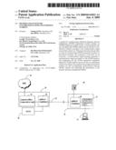
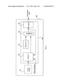
[0005]The xDSL based on passband transmission uses the Discrete Multi-Tone (DMT) modulation technology for modulation and demodulation. The system that provides multiple channels of DSL access is called "DSL Access Multiplexer (DSLAM)." The connection relations of a DSLAM system are shown in FIG. 1: The DSLAM 120 includes a customer premises transceiver unit 121 and a splitter/combiner 122. In the uplink direction, the customer premises transceiver unit 121 receives DSL signals from the computer 110, amplifies the received signals, and sends the amplified DSL signals to the splitter/combiner 122; the splitter/combiner 122 combines the DSL signals from the customer premises transceiver unit 121 and the POTS signals from the telephone terminal 130; the combined signals are transmitted through multiple Unshielded Twisted Pairs (UTPs) 140, and the splitter/combiner 151 of the peer DSLAM 150 receives the signals; the splitter/combiner 151 splits the received signals, sends the POTS signals to the Public Switched Telephone Network (PSTN) 160, and sends the DSL signals to the central office transceiver unit 152 of the DSLAM 150; and the central office transceiver unit 152 amplifies the received signals, and sends them to the Network Management System (NMS) 170. In the downlink direction, the signals are transmitted reversely.
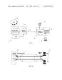
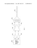
[0006]As the band applied to the xDSL technology is higher and higher, crosstalk becomes a nuisance, especially in a high band. FIG. 2A and FIG. 2B show the Near End Cross Talk (NEXT) and the Far End Cross Talk (FEXT) in the xDSL. As shown in FIG. 2A, port 1 and port 2 in the DSLAM 210 are connected with the Remote Terminal Unit (RTU) 211 through cables. The uplink and downlink channels of the xDSL are based on the frequency division multiplexing technology, so the NEXT causes little harm to the system performance. As shown in FIG. 2B, port 1 and port 2 of DSLAM 220 are connected with the RTU 221 respectively through cables. The uplink and downlink channels of the xDSL are based on the frequency division multiplexing technology, so the FEXT deteriorates the line transmission performance drastically. For example, when xDSL services are activated for multiple users in a bundle of cables, some lines may suffer from low transmission rate and instability or even xDSL services fail to be activated because of FEXT, leading to a low activation rate of the DSLAM.
[0007]In order to achieve higher rates or greater service radiuses, the prior art uses the binding technology. The binding technology is characterized by using multiple pairs of subscriber lines concurrently as physical transmission media. At the lower band (with lower FEXT), the comprehensive performance of the binding technology is roughly the linear sum of the performance of all subscriber lines. At the higher band (with higher FEXT), the comprehensive performance of the binding technology is far less than the linear sum of the performance of all subscriber lines as affected by FEXT. Technically, the binding process simply treats the crosstalk as noise, and cannot make the most of the information transferred in the crosstalk.
[0008]In order to solve the FEXT problem in the previous binding solution, a Dynamic Spectrum Management (DSM) technology emerges recently. The DSM technology solves the FEXT problem through Multi-Input and Multi-Output (MIMO) and vectored DSL technologies on the signal plane.
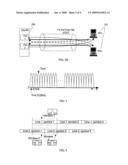
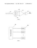
[0009]With respect to the modulation mode, the MIMO technology is OFDM. As shown in FIG. 3, the conception of the OFDM is to divide a band into multiple tones of narrower frequencies, with each tone bearing a certain quantity of bits. The frequency of each tone is narrow. Therefore, the transmission function of a channel in this band is approximately regarded as a constant which verges on distortion-free transmission and facilitates processing at the receiver side. Moreover, each tone is completely orthogonal, and the tones do not affect each other.
[0010]Both the optimization of the DSM technology and the crosstalk cancellation of the MIMO technology are based on the orthogonal feature mentioned above. Generally, the receiver of each previous xDSL modem treats the interference from other modems onto this modem as noise. Therefore, the data rate accomplishable on number k tone of number n user (bkn) can be calculated through a Shannon channel capacity formula:
b k n = log 2 ( 1 + h k n , n 2 s k n m ≠ n h k n , m 2 s k m + σ k n ) ##EQU00001##
[0011]In the above formula, hkn,n is the transmission function of number n line on number k tone; hkn,m, is the crosstalk function of number m line on number k tone against number n line; σkn is the noise power of number n line on number k tone; and skn is the transmitted power of number n line on number k tone.
[0012]The above formula shows that the whole DSM rate calculation is based on each tone due to the orthogonal feature of tones. If the orthogonal feature of each tone is damaged, all DSM algorithms will change, and the algorithms enumerated above will not be applicable.
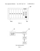
[0013]When the symbol (frame) is not synchronous between all lines, the orthogonal feature of the tone will be damaged. As shown in FIG. 4, line 1 is affected by the interference from line 2, and the symbols are not synchronous between line 1 and line 2. When line 1 performs OFDM demodulation, line 1 will handle some signals of symbol 1 and symbol 2 in line 2, which is equivalent to adding window 2 and window 3 on line 2 respectively. Evidently, window 2 and window 3 are shorter than the normal OFDM signals (as shown in window 1). Consequently, the spectrum width differs between window 2 and window 3, which damages the orthogonal feature of frequency. That is, the signals of different frequencies generate interference to each other.
SUMMARY
[0014]The present invention provides a method and system for synchronizing OFDM transmission symbols in order to synchronize the OFDM symbols and prevent damage to the orthogonal feature of the OFDM tones.
[0015]A method for synchronizing OFDM transmission symbols in an embodiment of the present invention includes: receiving, by an OFDM transmission module, synchronization signals; and adjusting the OFDM symbols sent by all lines to synchronous symbols according to the synchronization signals, and sending the symbols out.
[0016]In another embodiment of the present invention, a system for synchronizing OFDM transmission symbols includes: a synchronization signal generator, adapted to generate a synchronization signal and send it out; and an OFDM transmission module, adapted to receive the synchronization signal sent by the synchronization signal generator, and adjust the OFDM symbols sent by all lines to synchronous symbols according to the synchronization signal and send the symbols out.
[0017]In the present invention, a synchronization signal generator generates a synchronization signal and sends it to the OFDM transmission module; the OFDM transmission module adjusts the OFDM symbols sent by all lines to synchronous symbols according to the synchronization signal and send the symbols out, thus implementing synchronization between OFDM symbols and optimizing the performance of the DSM.
BRIEF DESCRIPTION OF THE DRAWINGS
[0018]In order to describe the technical solutions under the present invention and the prior art more clearly, the drawings for illustrating the embodiments of the present invention or the prior art are introduced briefly below. Evidently, the accompanying drawings are for exemplary purpose only, and those skilled in the art can derive other drawings from such accompanying drawings without making any creative effort.
[0019]FIG. 1 shows a xDSL system model;
[0020]FIG. 2A and FIG. 2B show the crosstalk in the xDSL;
[0021]FIG. 3 shows the OFDM tones;
[0022]FIG. 4 shows a circumstance that the orthogonal feature of the tone is damaged due to asynchronous OFDM symbols;
[0023]FIG. 5 shows the time sequence of synchronization signals in an embodiment of the present invention;
[0024]FIG. 6 is a circuit diagram of the synchronization signal generator in an embodiment of the present invention;
[0025]FIG. 7 is a circuit diagram of the synchronization signal transmitter interface in an embodiment of the present invention;
[0026]FIG. 8 is a circuit diagram of the synchronization signal receiver interface in an embodiment of the present invention;
[0027]FIG. 9 shows the first mode of using the synchronization signal in an embodiment of the present invention;
[0028]FIG. 10 shows the clock board corresponding to the first mode of using the synchronization signal in an embodiment of the present invention;
[0029]FIG. 11 shows the second mode of using the synchronization signal in an embodiment of the present invention;
[0030]FIG. 12 shows the clock board corresponding to the second mode of using the synchronization signal in an embodiment of the present invention; and
[0031]FIG. 13 shows transmission of synchronization signals when a remote DSLAM exists in an embodiment of the present invention.
DETAILED DESCRIPTION
[0032]The technical solution under the present invention is elaborated below with reference to the accompanying drawings. Evidently, the embodiments described below are for exemplary purpose only, without covering all embodiments of the present invention. Those skilled in the art can make no creative effort to derive all other embodiments from the embodiments described below, without departing from the protection scope of the present invention.
[0033]In the present invention, a synchronization signal generator generates a synchronization signal and sends it to the OFDM transmission module; the OFDM transmission module adjusts the OFDM symbols sent by all lines to synchronous symbols according to the synchronization signal and send the symbols out, thus preventing damage to the orthogonal feature of the OFDM tones caused by asynchronous OFDM symbols.
[0034]The present invention is hereinafter described in detail with reference to embodiments and accompanying drawings.
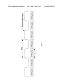
[0035]As shown in FIG. 5, this embodiment provides a square-wave signal whose period is double of the length of the OFDM symbol. Nevertheless, the period of the square-wave signal may be N-fold or 1/N-fold of the length of the OFDM symbol, where N is a natural number greater than 2. To put it briefly, we hereinafter suppose that the period of the square-wave signal is double of the length of the OFDM symbol. The square-wave signal may be generated by a stand-alone device located in the equipment room of the central office, or by a DSLAM of the central office. The circuit of generating a square-wave signal is shown in FIG. 6.
[0036]A synchronization signal generating circuit 609 includes two modules: a clock source or high-precision crystal oscillator 601; and a digital logic circuit 608. The clock source or high-precision crystal oscillator 601 generates a clock signal and sends it to a counter 602 for counting. The length of the OFDM symbol is stored in a register 603. In the case that the count of the counter 602 is equal to the length of the OFDM symbol stored in the register 603, a comparer 604 generates pulse. The pulse is divided into two pulses: one for generating synchronization signals for a T trigger 605; and the other for resetting the counter 602. The counter 602 contains a resetting interface, adapted to connect the power-on reset signal so that the digital logic circuit 608 can be reset after being powered on.
[0037]The clock source or high-precision crystal oscillator 601 (for example, constant-temperature crystal oscillator) requires a high precision.
[0038]The value in the register 603 depends on the clock frequency of the clock source or high-precision crystal oscillator 601 as well as the period of the OFDM symbol. For example, if the clock frequency of the clock source or high-precision crystal oscillator 601 is 35.328 MHz and the period of the OFDM symbol is 250 ms, the value in the register 603 will be: 35.328×106×250×10-3=8832000.
[0039]If the synchronization signal generating circuit is located in a stand-alone device in the equipment room of the central office, an analog circuit interface is required for transmitting the synchronization signal to the DSLAM. The interface circuit at the transmitter side is shown in FIG. 7.
[0040]The synchronization signal generated by the synchronization signal generating circuit 609 passes through a co-phase amplifier 701 and an inverse-phase amplifier 702, and is sent to the input side of a dual-end driver 703. The signal driven by the dual-end driver 703 passes through a matching resistor 706 and is sent to a coupler 704, and finally coupled to a twisted pair 705. Proper protection components should be connected to the output side of the coupler 704, depending on the environment of the twisted pair.
[0041]The interface circuit of the receiver is shown in FIG. 8. The signal is transmitted by the twisted pair 705, and is sent to a dual-end amplifier 801 through a coupler 804. A matching resistor 806 should be connected at the receiver to prevent signal deterioration caused by signal reflection. The signal output by the dual-end amplifier 801 is synchronous after passing through a hysteresis comparer 802 with dual-end input. Likewise, proper protection components should be connected to the input side of the line, depending on the environment of the twisted pair.
[0042]In the practical application, the synchronization signal generated above can be used in the following two ways:
[0043](i) As shown in FIG. 9, a synchronization signal generator 901 generates multiple drive signals, and drives more than one DSLAM 902 directly through a twisted pair. The synchronization signal generator 901 consists of a function circuit shown in FIG. 7 and other servo circuits such as power supply. The DSLAM 902 may contain the function circuit (receiving circuit) shown in FIG. 8 and the corresponding servo circuit. As shown in FIG. 10, the receiving circuit may be a stand-alone board of the DSLAM 902 (hereinafter referred to as "clock board"). The clock board includes a synchronization signal physical interface 9021 for connecting the twisted pair which transmits synchronization signals; the receiving circuit may also be integrated onto a function circuit on the DSLAM mainboard.
[0044](ii) The second mode of using the synchronization signals is shown in FIG. 11. The synchronization signal generator 901 outputs only one signal, but the DSLAM 902 is capable of concatenation. The synchronization signal generator 901 includes a function circuit shown in FIG. 7 and other servo circuits such as power supply. The DSLAM 902 contains not only the receiving circuit shown in FIG. 8, but also the transmitting circuit shown in FIG. 7 and other server circuits such as power supply.
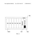
[0045]In the DSLAM 902, the previous circuits can be located on a stand-alone board, or integrated onto the mainboard. The location in a stand-alone board is shown in FIG. 12, in which the clock board contains two physical interfaces: one is a physical interface for inputting synchronization signals 1201 and the other is a physical interface for outputting synchronization signals 1202. The physical interface for outputting synchronization signals 1202 is adapted to connect the physical interface for inputting synchronization signals of another DSLAM.
[0046]The received synchronization signals may be distributed to different boards through the backplane wires, and further distributed to different chips on the board. The distribution through a backplane comes in two types: busbar mode and distribution mode.
[0047]If the signal received by the receiving circuit in the DSLAM is of low quality, especially when the previous busbar mode applies, the signal quality may be low due to impedance intermittence. This problem can be solved by a phase-locked loop circuit. The phase-locked loop circuit restores high-quality synchronization signals, and generates a synchronous working clock. In this way, the DSL line of the DSLAM can use the clock and further improve the orthogonal feature of the line.
[0048]After the DSLAM receives the synchronization signal, the synchronization information can be obtained by detecting the cross-zero point of the synchronization signal. The OFDM symbol can be synchronized only if the start time of the OFDM symbol corresponds to the cross-zero point of the synchronization signal. The word "correspond" here does not mean strict corresponding relationship between the start time of the OFDM symbol and the cross-zero point of the synchronization signal, and a certain delay is allowed only if the OFDM symbol can be synchronized. The synchronization information can be obtained by detecting other points of the synchronization signal rather than detecting the correspondence to the cross-zero point, so long as the OFDM symbol can be synchronized.
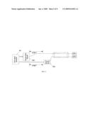
[0049]If a far-end DSLAM exists, as shown in FIG. 13, the synchronization signal generator 901 generates synchronization signals. Due to transmission delay, although a central office DSLAM 1302 and a far-end DSLAM 1303 use the same synchronization signal, the synchronization signal received by the far-end DSLAM 1303 is later than the synchronization signal received by the central office DSLAM 1302 because the former is transmitted for an extra length 1. However, the OFDM symbol sent by the central office DSLAM 1302 may be exactly synchronous with the OFDM symbol sent by the far-end DSLAM 1303 when arriving at the location of the far-end DSLAM 1303 after a delay of length 2. That depends on the duration of length 1 and length 2, the transmission media of the two lengths, and the delay of the DSLAM in processing the synchronization signals. Therefore, an extra time sequence adjusting unit can be added into the synchronization signal generator 901 to adjust the synchronization signals of the far-end DSLAM 1303 and ensure that the OFDM symbol sent by the central office DSLAM 1302 is exactly synchronous with the OFDM symbol sent by the far-end DSLAM 1303 when arriving at the location of the far-end DSLAM 1303.
[0050]It should be noted that the "central office DSLAM," or "central office DSLAM and far-end DSLAM" mentioned in the previous embodiment is the OFDM transmission module.
[0051]The present invention may adopt not only the square-wave signal mentioned above, but also other signals such as sine wave signal, triangle wave signal and pulse signal which carry period information, so long as the period of such periodical signal is greater than or equal to the period of the OFDM symbol and is an integer multiple of the period of the OFDM symbol.
[0052]Taking a sine wave signal as an example, after a sine wave synchronization signal is generated, it is amplified, filtered and driven, and is transmitted to the DSLAM or other devices with the DSLAM functions through a transmission line. At the receiver, the sine wave signal is converted into a square-wave signal, whereupon the operations are the same as those of a square-wave signal described above. The conversion from a sine-wave synchronization signal to a square-wave signal is a well-known technology, and is not repeated here any further.
[0053]In the present invention, a synchronization signal generator generates a synchronization signal and sends it to the OFDM transmission module; the OFDM transmission module adjusts the OFDM symbols sent by all lines to synchronous symbols according to the synchronization signal and send the symbols out, thus implementing synchronization between OFDM symbols and optimizing the performance of the DSM.
[0054]The technical solution under the present invention is applicable not only to DSLAM, but also to other OFDM transmission equipment such as WiMax base stations and the equipment that transmits OFDM on a coax cable or power cable.
[0055]Ordinary technical personnel in this field may understand that all or part of the steps in the preceding embodiments can be completed through a program which instructs related hardware. The program may be stored in a readable storage medium, for example, ROM/RAM, disk, and CD in a computer.
[0056]It is understandable that although the invention has been described through some exemplary embodiments, the invention is not limited to such embodiments. Those skilled in the art can make no creative effort to derive all other embodiments from the embodiments herein through modification and equivalent substitutions, without departing from the protection scope of the present invention.
Claims:
1. A method for synchronizing orthogonal frequency division multiplexing
(OFDM) transmission symbols, comprising:receiving, by an OFDM
transmission module, synchronization signals; andadjusting the OFDM
symbols sent by all lines to synchronous symbols according to the
synchronization signals, and sending the symbols out.
2. The method of claim 1, wherein the synchronization signal is generated by a synchronization signal generator and its period is 2N-fold or 1/2N-fold of the length of the OFDM symbol, wherein N is a natural number.
3. The method of claim 2, wherein the sending out of the OFDM symbol according to the synchronization signal comprises:controlling, by the OFDM transmission module, the start time of the OFDM symbol of each line to correspond to the cross-zero point of the synchronization signal after receiving a synchronization signal so that the OFDM symbols of all lines can be synchronized and sent to the DSLAM.
4. The method of claim 1, wherein the receiving of the synchronization signal comprises:processing, by the OFDM transmission module, the synchronization signal through a phase-locked loop circuit after receiving the synchronization signal through a synchronization signal receiving port.
5. The method of claim 1, wherein the OFDM transmission module is a central office DSL access multiplexer (DSLAM) and/or a far-end DSLAM.
6. The method of claim 5, wherein the synchronization signal is adjusted through time sequence adjusting circuit in the synchronization signal generator so that the far-end DSLAM and the central office DSLAM receive the synchronization signal synchronously.
7. A system for synchronizing orthogonal frequency division multiplexing (OFDM) transmission symbols, comprising:a synchronization signal generator, adapted to generate a synchronization signal and send it out; andan OFDM transmission module, adapted to receive the synchronization signal sent by the synchronization signal generator, and adjust the OFDM symbols sent by all lines to synchronous symbols according to the synchronization signal and send the symbols out.
8. The system of claim 7, wherein the period of the synchronization signal generated by a synchronization signal generator is 2N-fold or 1/2N-fold of the length of the OFDM symbol, wherein N is a natural number.
9. The system of claim 8, comprising: a controlling module, adapted to control the start time of the OFDM symbol of each line to correspond to the cross-zero point of the synchronization signal so that the OFDM symbols of all lines are synchronized.
10. The system of claim 7, wherein the OFDM transmission module is a far-end DSL access multiplexer (DSLAM) or a central office DSLAM.
11. The system of claim 10, wherein the synchronization signal generator comprises a time sequence adjusting circuit, adapted to adjust the synchronization signal so that the far-end DSLAM and the central office DSLAM receive the synchronization signal synchronously.
12. The system of claim 7, wherein:the synchronization signal generator comprises a synchronization signal generating circuit comprising a clock source and a digital logical circuit; wherein:the digital logical circuit comprises a counter, a register, a comparer, and a T trigger; wherein:the clock source is adapted to generate clock signals;the counter is adapted to count according to the clock signals provided by the clock source;the register is adapted to store the length of the OFDM symbol; andthe comparer is adapted to generate a pulse when the count of the counter is equal to the length of the OFDM symbol stored in the register; wherein the pulse is divided into two pulses: one for generating synchronization signals for the T trigger, the other for resetting the counter.
13. The system of claim 12, wherein the length of the OFDM symbol stored in the register is the product of the clock frequency of the clock source and the period of the OFDM symbol.
Description:
CROSS-REFERENCE TO RELATED APPLICATIONS
[0001]This application is a continuation of International Patent Application No. PCT/CN2007/070192, filed Jun. 27, 2007, which claims priority to Chinese Patent Application No. 200610061476.1, filed Jun. 30, 2006, both of which are hereby incorporated by reference in their entirety.
FIELD OF THE INVENTION
[0002]The present invention relates to the field of the Digital Subscriber Line (DSL) field, and in particular, to an Orthogonal Frequency Division Multiplexing (OFDM) technology, more particularly, to a method and system for synchronizing OFDM transmission symbols.
BACKGROUND
[0003]The DSL technology is a high-speed data transmission technology implemented through Unshielded Twisted Pair (UTP), including Asymmetrical Digital Subscriber Line (ADSL), Very-high-bit-rate Digital Subscriber Line (VDSL), Integrated Services Digital Network (ISDN)-based Digital Subscriber Line (IDSL), and Single-pair High-bit-rate Digital Subscriber Line (SHDSL).
[0004]Among various DSL technologies (xDSL), except the xDSL based on baseband transmission (for example, IDSL and SHDSL), the xDSL technologies based on passband transmission coexist with the Plain Old Telephone Service (POTS) on a twisted pair by means of the frequency division multiplexing technology, in which the xDSL occupies the high band and the POTS occupies the baseband part below 4 KHz; and the POTS signals are separated from the xDSL signals through a splitter, or combined with the xDSL signals through a combiner.
[0005]The xDSL based on passband transmission uses the Discrete Multi-Tone (DMT) modulation technology for modulation and demodulation. The system that provides multiple channels of DSL access is called "DSL Access Multiplexer (DSLAM)." The connection relations of a DSLAM system are shown in FIG. 1: The DSLAM 120 includes a customer premises transceiver unit 121 and a splitter/combiner 122. In the uplink direction, the customer premises transceiver unit 121 receives DSL signals from the computer 110, amplifies the received signals, and sends the amplified DSL signals to the splitter/combiner 122; the splitter/combiner 122 combines the DSL signals from the customer premises transceiver unit 121 and the POTS signals from the telephone terminal 130; the combined signals are transmitted through multiple Unshielded Twisted Pairs (UTPs) 140, and the splitter/combiner 151 of the peer DSLAM 150 receives the signals; the splitter/combiner 151 splits the received signals, sends the POTS signals to the Public Switched Telephone Network (PSTN) 160, and sends the DSL signals to the central office transceiver unit 152 of the DSLAM 150; and the central office transceiver unit 152 amplifies the received signals, and sends them to the Network Management System (NMS) 170. In the downlink direction, the signals are transmitted reversely.
[0006]As the band applied to the xDSL technology is higher and higher, crosstalk becomes a nuisance, especially in a high band. FIG. 2A and FIG. 2B show the Near End Cross Talk (NEXT) and the Far End Cross Talk (FEXT) in the xDSL. As shown in FIG. 2A, port 1 and port 2 in the DSLAM 210 are connected with the Remote Terminal Unit (RTU) 211 through cables. The uplink and downlink channels of the xDSL are based on the frequency division multiplexing technology, so the NEXT causes little harm to the system performance. As shown in FIG. 2B, port 1 and port 2 of DSLAM 220 are connected with the RTU 221 respectively through cables. The uplink and downlink channels of the xDSL are based on the frequency division multiplexing technology, so the FEXT deteriorates the line transmission performance drastically. For example, when xDSL services are activated for multiple users in a bundle of cables, some lines may suffer from low transmission rate and instability or even xDSL services fail to be activated because of FEXT, leading to a low activation rate of the DSLAM.
[0007]In order to achieve higher rates or greater service radiuses, the prior art uses the binding technology. The binding technology is characterized by using multiple pairs of subscriber lines concurrently as physical transmission media. At the lower band (with lower FEXT), the comprehensive performance of the binding technology is roughly the linear sum of the performance of all subscriber lines. At the higher band (with higher FEXT), the comprehensive performance of the binding technology is far less than the linear sum of the performance of all subscriber lines as affected by FEXT. Technically, the binding process simply treats the crosstalk as noise, and cannot make the most of the information transferred in the crosstalk.
[0008]In order to solve the FEXT problem in the previous binding solution, a Dynamic Spectrum Management (DSM) technology emerges recently. The DSM technology solves the FEXT problem through Multi-Input and Multi-Output (MIMO) and vectored DSL technologies on the signal plane.
[0009]With respect to the modulation mode, the MIMO technology is OFDM. As shown in FIG. 3, the conception of the OFDM is to divide a band into multiple tones of narrower frequencies, with each tone bearing a certain quantity of bits. The frequency of each tone is narrow. Therefore, the transmission function of a channel in this band is approximately regarded as a constant which verges on distortion-free transmission and facilitates processing at the receiver side. Moreover, each tone is completely orthogonal, and the tones do not affect each other.
[0010]Both the optimization of the DSM technology and the crosstalk cancellation of the MIMO technology are based on the orthogonal feature mentioned above. Generally, the receiver of each previous xDSL modem treats the interference from other modems onto this modem as noise. Therefore, the data rate accomplishable on number k tone of number n user (bkn) can be calculated through a Shannon channel capacity formula:
b k n = log 2 ( 1 + h k n , n 2 s k n m ≠ n h k n , m 2 s k m + σ k n ) ##EQU00001##
[0011]In the above formula, hkn,n is the transmission function of number n line on number k tone; hkn,m, is the crosstalk function of number m line on number k tone against number n line; σkn is the noise power of number n line on number k tone; and skn is the transmitted power of number n line on number k tone.
[0012]The above formula shows that the whole DSM rate calculation is based on each tone due to the orthogonal feature of tones. If the orthogonal feature of each tone is damaged, all DSM algorithms will change, and the algorithms enumerated above will not be applicable.
[0013]When the symbol (frame) is not synchronous between all lines, the orthogonal feature of the tone will be damaged. As shown in FIG. 4, line 1 is affected by the interference from line 2, and the symbols are not synchronous between line 1 and line 2. When line 1 performs OFDM demodulation, line 1 will handle some signals of symbol 1 and symbol 2 in line 2, which is equivalent to adding window 2 and window 3 on line 2 respectively. Evidently, window 2 and window 3 are shorter than the normal OFDM signals (as shown in window 1). Consequently, the spectrum width differs between window 2 and window 3, which damages the orthogonal feature of frequency. That is, the signals of different frequencies generate interference to each other.
SUMMARY
[0014]The present invention provides a method and system for synchronizing OFDM transmission symbols in order to synchronize the OFDM symbols and prevent damage to the orthogonal feature of the OFDM tones.
[0015]A method for synchronizing OFDM transmission symbols in an embodiment of the present invention includes: receiving, by an OFDM transmission module, synchronization signals; and adjusting the OFDM symbols sent by all lines to synchronous symbols according to the synchronization signals, and sending the symbols out.
[0016]In another embodiment of the present invention, a system for synchronizing OFDM transmission symbols includes: a synchronization signal generator, adapted to generate a synchronization signal and send it out; and an OFDM transmission module, adapted to receive the synchronization signal sent by the synchronization signal generator, and adjust the OFDM symbols sent by all lines to synchronous symbols according to the synchronization signal and send the symbols out.
[0017]In the present invention, a synchronization signal generator generates a synchronization signal and sends it to the OFDM transmission module; the OFDM transmission module adjusts the OFDM symbols sent by all lines to synchronous symbols according to the synchronization signal and send the symbols out, thus implementing synchronization between OFDM symbols and optimizing the performance of the DSM.
BRIEF DESCRIPTION OF THE DRAWINGS
[0018]In order to describe the technical solutions under the present invention and the prior art more clearly, the drawings for illustrating the embodiments of the present invention or the prior art are introduced briefly below. Evidently, the accompanying drawings are for exemplary purpose only, and those skilled in the art can derive other drawings from such accompanying drawings without making any creative effort.
[0019]FIG. 1 shows a xDSL system model;
[0020]FIG. 2A and FIG. 2B show the crosstalk in the xDSL;
[0021]FIG. 3 shows the OFDM tones;
[0022]FIG. 4 shows a circumstance that the orthogonal feature of the tone is damaged due to asynchronous OFDM symbols;
[0023]FIG. 5 shows the time sequence of synchronization signals in an embodiment of the present invention;
[0024]FIG. 6 is a circuit diagram of the synchronization signal generator in an embodiment of the present invention;
[0025]FIG. 7 is a circuit diagram of the synchronization signal transmitter interface in an embodiment of the present invention;
[0026]FIG. 8 is a circuit diagram of the synchronization signal receiver interface in an embodiment of the present invention;
[0027]FIG. 9 shows the first mode of using the synchronization signal in an embodiment of the present invention;
[0028]FIG. 10 shows the clock board corresponding to the first mode of using the synchronization signal in an embodiment of the present invention;
[0029]FIG. 11 shows the second mode of using the synchronization signal in an embodiment of the present invention;
[0030]FIG. 12 shows the clock board corresponding to the second mode of using the synchronization signal in an embodiment of the present invention; and
[0031]FIG. 13 shows transmission of synchronization signals when a remote DSLAM exists in an embodiment of the present invention.
DETAILED DESCRIPTION
[0032]The technical solution under the present invention is elaborated below with reference to the accompanying drawings. Evidently, the embodiments described below are for exemplary purpose only, without covering all embodiments of the present invention. Those skilled in the art can make no creative effort to derive all other embodiments from the embodiments described below, without departing from the protection scope of the present invention.
[0033]In the present invention, a synchronization signal generator generates a synchronization signal and sends it to the OFDM transmission module; the OFDM transmission module adjusts the OFDM symbols sent by all lines to synchronous symbols according to the synchronization signal and send the symbols out, thus preventing damage to the orthogonal feature of the OFDM tones caused by asynchronous OFDM symbols.
[0034]The present invention is hereinafter described in detail with reference to embodiments and accompanying drawings.
[0035]As shown in FIG. 5, this embodiment provides a square-wave signal whose period is double of the length of the OFDM symbol. Nevertheless, the period of the square-wave signal may be N-fold or 1/N-fold of the length of the OFDM symbol, where N is a natural number greater than 2. To put it briefly, we hereinafter suppose that the period of the square-wave signal is double of the length of the OFDM symbol. The square-wave signal may be generated by a stand-alone device located in the equipment room of the central office, or by a DSLAM of the central office. The circuit of generating a square-wave signal is shown in FIG. 6.
[0036]A synchronization signal generating circuit 609 includes two modules: a clock source or high-precision crystal oscillator 601; and a digital logic circuit 608. The clock source or high-precision crystal oscillator 601 generates a clock signal and sends it to a counter 602 for counting. The length of the OFDM symbol is stored in a register 603. In the case that the count of the counter 602 is equal to the length of the OFDM symbol stored in the register 603, a comparer 604 generates pulse. The pulse is divided into two pulses: one for generating synchronization signals for a T trigger 605; and the other for resetting the counter 602. The counter 602 contains a resetting interface, adapted to connect the power-on reset signal so that the digital logic circuit 608 can be reset after being powered on.
[0037]The clock source or high-precision crystal oscillator 601 (for example, constant-temperature crystal oscillator) requires a high precision.
[0038]The value in the register 603 depends on the clock frequency of the clock source or high-precision crystal oscillator 601 as well as the period of the OFDM symbol. For example, if the clock frequency of the clock source or high-precision crystal oscillator 601 is 35.328 MHz and the period of the OFDM symbol is 250 ms, the value in the register 603 will be: 35.328×106×250×10-3=8832000.
[0039]If the synchronization signal generating circuit is located in a stand-alone device in the equipment room of the central office, an analog circuit interface is required for transmitting the synchronization signal to the DSLAM. The interface circuit at the transmitter side is shown in FIG. 7.
[0040]The synchronization signal generated by the synchronization signal generating circuit 609 passes through a co-phase amplifier 701 and an inverse-phase amplifier 702, and is sent to the input side of a dual-end driver 703. The signal driven by the dual-end driver 703 passes through a matching resistor 706 and is sent to a coupler 704, and finally coupled to a twisted pair 705. Proper protection components should be connected to the output side of the coupler 704, depending on the environment of the twisted pair.
[0041]The interface circuit of the receiver is shown in FIG. 8. The signal is transmitted by the twisted pair 705, and is sent to a dual-end amplifier 801 through a coupler 804. A matching resistor 806 should be connected at the receiver to prevent signal deterioration caused by signal reflection. The signal output by the dual-end amplifier 801 is synchronous after passing through a hysteresis comparer 802 with dual-end input. Likewise, proper protection components should be connected to the input side of the line, depending on the environment of the twisted pair.
[0042]In the practical application, the synchronization signal generated above can be used in the following two ways:
[0043](i) As shown in FIG. 9, a synchronization signal generator 901 generates multiple drive signals, and drives more than one DSLAM 902 directly through a twisted pair. The synchronization signal generator 901 consists of a function circuit shown in FIG. 7 and other servo circuits such as power supply. The DSLAM 902 may contain the function circuit (receiving circuit) shown in FIG. 8 and the corresponding servo circuit. As shown in FIG. 10, the receiving circuit may be a stand-alone board of the DSLAM 902 (hereinafter referred to as "clock board"). The clock board includes a synchronization signal physical interface 9021 for connecting the twisted pair which transmits synchronization signals; the receiving circuit may also be integrated onto a function circuit on the DSLAM mainboard.
[0044](ii) The second mode of using the synchronization signals is shown in FIG. 11. The synchronization signal generator 901 outputs only one signal, but the DSLAM 902 is capable of concatenation. The synchronization signal generator 901 includes a function circuit shown in FIG. 7 and other servo circuits such as power supply. The DSLAM 902 contains not only the receiving circuit shown in FIG. 8, but also the transmitting circuit shown in FIG. 7 and other server circuits such as power supply.
[0045]In the DSLAM 902, the previous circuits can be located on a stand-alone board, or integrated onto the mainboard. The location in a stand-alone board is shown in FIG. 12, in which the clock board contains two physical interfaces: one is a physical interface for inputting synchronization signals 1201 and the other is a physical interface for outputting synchronization signals 1202. The physical interface for outputting synchronization signals 1202 is adapted to connect the physical interface for inputting synchronization signals of another DSLAM.
[0046]The received synchronization signals may be distributed to different boards through the backplane wires, and further distributed to different chips on the board. The distribution through a backplane comes in two types: busbar mode and distribution mode.
[0047]If the signal received by the receiving circuit in the DSLAM is of low quality, especially when the previous busbar mode applies, the signal quality may be low due to impedance intermittence. This problem can be solved by a phase-locked loop circuit. The phase-locked loop circuit restores high-quality synchronization signals, and generates a synchronous working clock. In this way, the DSL line of the DSLAM can use the clock and further improve the orthogonal feature of the line.
[0048]After the DSLAM receives the synchronization signal, the synchronization information can be obtained by detecting the cross-zero point of the synchronization signal. The OFDM symbol can be synchronized only if the start time of the OFDM symbol corresponds to the cross-zero point of the synchronization signal. The word "correspond" here does not mean strict corresponding relationship between the start time of the OFDM symbol and the cross-zero point of the synchronization signal, and a certain delay is allowed only if the OFDM symbol can be synchronized. The synchronization information can be obtained by detecting other points of the synchronization signal rather than detecting the correspondence to the cross-zero point, so long as the OFDM symbol can be synchronized.
[0049]If a far-end DSLAM exists, as shown in FIG. 13, the synchronization signal generator 901 generates synchronization signals. Due to transmission delay, although a central office DSLAM 1302 and a far-end DSLAM 1303 use the same synchronization signal, the synchronization signal received by the far-end DSLAM 1303 is later than the synchronization signal received by the central office DSLAM 1302 because the former is transmitted for an extra length 1. However, the OFDM symbol sent by the central office DSLAM 1302 may be exactly synchronous with the OFDM symbol sent by the far-end DSLAM 1303 when arriving at the location of the far-end DSLAM 1303 after a delay of length 2. That depends on the duration of length 1 and length 2, the transmission media of the two lengths, and the delay of the DSLAM in processing the synchronization signals. Therefore, an extra time sequence adjusting unit can be added into the synchronization signal generator 901 to adjust the synchronization signals of the far-end DSLAM 1303 and ensure that the OFDM symbol sent by the central office DSLAM 1302 is exactly synchronous with the OFDM symbol sent by the far-end DSLAM 1303 when arriving at the location of the far-end DSLAM 1303.
[0050]It should be noted that the "central office DSLAM," or "central office DSLAM and far-end DSLAM" mentioned in the previous embodiment is the OFDM transmission module.
[0051]The present invention may adopt not only the square-wave signal mentioned above, but also other signals such as sine wave signal, triangle wave signal and pulse signal which carry period information, so long as the period of such periodical signal is greater than or equal to the period of the OFDM symbol and is an integer multiple of the period of the OFDM symbol.
[0052]Taking a sine wave signal as an example, after a sine wave synchronization signal is generated, it is amplified, filtered and driven, and is transmitted to the DSLAM or other devices with the DSLAM functions through a transmission line. At the receiver, the sine wave signal is converted into a square-wave signal, whereupon the operations are the same as those of a square-wave signal described above. The conversion from a sine-wave synchronization signal to a square-wave signal is a well-known technology, and is not repeated here any further.
[0053]In the present invention, a synchronization signal generator generates a synchronization signal and sends it to the OFDM transmission module; the OFDM transmission module adjusts the OFDM symbols sent by all lines to synchronous symbols according to the synchronization signal and send the symbols out, thus implementing synchronization between OFDM symbols and optimizing the performance of the DSM.
[0054]The technical solution under the present invention is applicable not only to DSLAM, but also to other OFDM transmission equipment such as WiMax base stations and the equipment that transmits OFDM on a coax cable or power cable.
[0055]Ordinary technical personnel in this field may understand that all or part of the steps in the preceding embodiments can be completed through a program which instructs related hardware. The program may be stored in a readable storage medium, for example, ROM/RAM, disk, and CD in a computer.
[0056]It is understandable that although the invention has been described through some exemplary embodiments, the invention is not limited to such embodiments. Those skilled in the art can make no creative effort to derive all other embodiments from the embodiments herein through modification and equivalent substitutions, without departing from the protection scope of the present invention.
User Contributions:
Comment about this patent or add new information about this topic:
Images included with this patent application:
 |  |
 |  |
 |  |
 |  |
 |  |
| Similar patent applications: | |
| Date | Title |
|---|---|
| 2013-09-05 | Non-synchronized adpcm with discontinuous transmission |
| 2012-06-28 | System and method for synchronous transmission of content |
| 2008-12-25 | Generation of a transmission signal |
| 2009-02-05 | Method for reducing ambiguity levels of transmitted symbols |
| 2010-02-04 | Method and apparatus for controlling dsl line transmission power |
| New patent applications in this class: | |
| Date | Title |
|---|---|
| 2022-05-05 | Method and apparatus for receiving wireless signal in wireless communication system |
| 2019-05-16 | Method and device for transmitting information, and storage medium |
| 2019-05-16 | Sequence-based signal processing method and apparatus |
| 2019-05-16 | Channel estimation circuit and associated channel estimation method |
| 2019-05-16 | Method and apparatus to receive and transmit data in a mobile communication system |
| New patent applications from these inventors: | |
| Date | Title |
|---|---|
| 2022-07-28 | Electronic atomization device and method for detecting intake amount of aerosol-forming matrix thereof |
| 2022-03-10 | Secure face image transmission method, apparatuses, and electronic device |
| 2021-11-25 | Data communication method and system, electronic device, chip and storage medium |
| 2021-02-04 | Electronic atomization devices, methods for heating control, and computer devices |
| 2021-01-14 | Method for information processing and non-transitory computer readable storage medium |
| Top Inventors for class "Pulse or digital communications" | |
| Rank | Inventor's name |
|---|---|
| 1 | Marta Karczewicz |
| 2 | Takeshi Chujoh |
| 3 | Shinichiro Koto |
| 4 | Yoshihiro Kikuchi |
| 5 | Takahiro Nishi |