Patent application title: Mountable linear light welt
Inventors:
Kevin Bruce (Snohomish, WA, US)
Luis Lorca-Merono (Snohomish, WA, US)
IPC8 Class: AF21V916FI
USPC Class:
362 84
Class name: Illumination light source or light source support and luminescent material
Publication date: 2009-06-04
Patent application number: 20090141475
easier to attach to a desired surface or joint.
The welt includes a transparent or semi-transparent sheath casing
circular or oval in cross-section with at least one integrally formed,
laterally extending wing member. The wing member is a relatively thin
structure that extends longitudinally over a portion or the entire length
of the outer casing. In the preferred embodiment, the outer edges of the
wing member is converge are converged towards their outer edges thereby
enabling the wing to be placed into a joint space. A suitable attachment
means, such as sewing, an adhesive, or a closed joint, may be used to
attach the wing to the desired surface or joint while allowing the outer
casing to be exposed. Located inside the outer sheath is a continuous
linear light.Claims:
1. A continuously mountable linear light, comprising:a. a transparent,
continuous outer sheath casing;b. a continuous, integrally formed, wing
member that extends laterally from said outer sheath casing, said wing
member extends substantially the entire length of said outer sheath
casing thereby enabling said light source to be continuously attached
along its entire length to a support surface or object; and,c. a linear
electric light source located inside said casing.
2. The continuously mountable linear light, as recited in claim 1, wherein said outer sheath casing and wing member are made of polyvinyl chloride.
3. The continuously mounted linear light, as recited in claim 1, wherein said wing member has converging surfaces.
4. The continuous mounted linear light as recited in claim 1, further including a plurality of slits formed on said wing member enabling said electroluminescent welt to bend when mounted on a surface.
5. The continuously mounted linear light, as recited in claim 3, wherein said wing member is made of polyvinyl chloride.
6. The continuously mounted linear light, as recited in claim 1, further including a second wing member extending laterally from said outer sheath casing.
7. The continuous mounted linear light, as recited in claim 6, wherein said second wing member extends from said outer sheath casing on an opposite side of said first wing member.
8. The continuous mounted linear light, as recited in claim 7, wherein said second wing member is made of polyvinyl chloride.
9. The continuous mounted linear light, as recited in claim 6, wherein said second wing member has converging surfaces.
10. The continuous mounted linear light as recited in claim 3, further including a plurality of slits formed on said wing member enabling said electroluminescent welt to bend when mounted on a surface.Description:
[0001]This is a continuation application based on utility patent
application (Ser. No. 10/152,364), filed May 20, 2002 now U.S. Pat. No.
7,425,079 and design patent application (Ser. No. 29/138,485) filed on
Mar. 12, 2001, now U.S. Pat. No. D 457,299
BACKGROUND OF THE INVENTION
[0002]1. Field of the Invention
[0003]The present invention relates to flexible, tubular light sources and, more particularly to such products that can be easily mounted to a surface.
[0004]2. Description of the Related Art
[0005]Electroluminescence is the conversion of electrical energy into light by the activation of a phosphor layer by an alternating electrical current. Electroluminescent lighting consists of a layer of phosphor placed between two thin conductors which, when applied to a 400 to 2000 Hz AC circuit cause the layer of phosphor to rapidly charge and discharge and emit light. Dyes and filters are mixed or added to the electroluminescent lighting to emit specific colors. Also, inverters may be used to invert a DC power source from a battery into an alternating circuit at a specific current and voltage needed to cause electroluminescence. Examples of electroluminescent lighting are sold by Elam Electroluminescent Industries, Ltd, located in Jerusalem, Israel, under the trademark LyTec, and disclosed in U.S. Pat. Nos. 5,485,355 and 5,869,930, now incorporated herein.
[0006]The inner and outer conductors used in the electroluminescent lighting disclosed above are disposed inside a tubular-shaped outer insulation layer filed with an inner insulation layer. Because the outer insulation layer is circular in cross section, it is difficult to attached or mount securely to a flat surface or joint. Typically, clips or adhesives are used to attach the outer insulation layer to a flat surface which is cosmetically unacceptable in some applications.
[0007]What is needed is an improved lighting with an integrally attached structure that enables it to be easily mounted to a surface or joint.
SUMMARY OF THE INVENTION
[0008]It is an object of the present invention to provide a mountable linear light welt with an integrally attached wing that enables it to be easily mounted to a surface or joint. This object and other objects which will become apparent is met by the mountable light welt that includes an linear light source, such as an electroluminescent filament with a center conductor, and at least one outer conductor with an electroluminescent chemical dispersed therein that undergo electroluminescence when excited with by a suitable AC current. The welt includes a transparent or semi-transparent sheath casing which is circular or oval in cross-section designed to contain the linear light source. Integrally formed and laterally extending from the casing is a wing member. The wing member is a relatively thin structure that extends longitudinally over a portion or over the entire length of the outer casing. In the preferred embodiment, the outer edges of the wing member are converged towards their outer edges thereby enabling the wing to be placed into a joint space. A suitable attachment means, such as sewing thread, a suitable adhesive, or a closed welded joint may be used to mount the wing to the desired surface or joint while allowing the outer casing to be exposed.
DESCRIPTION OF THE DRAWINGS
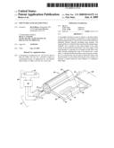
[0009]FIG. 1 is a perspective view of the mountable electroluminescent welt with one wing member.
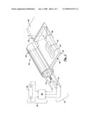
[0010]FIG. 2 is a perspective view of the invention of the mountable linear light welt with the wing member attached between two surfaces.
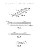
[0011]FIG. 3 is a top plan view of the invention shown in FIG. 2.
[0012]FIG. 4 is a side elevational view of the invention shown in FIGS. 2 and 3.
[0013]FIG. 5 is an end elevational view of the invention shown in FIGS. 2-4.
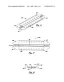
[0014]FIG. 6 is a perspective view of a second embodiment of the welt with two wing members disposed between to joined surfaces.
[0015]FIG. 7 is a top plan view of the welt shown in FIG. 6.
[0016]FIG. 8 is an end elevational view of the invention show in FIGS. 6 and 7.
DESCRIPTION OF THE PREFERRED EMBODIMENT(S)
[0017]Shown in the accompanying FIGS. 1-8, is a mountable linear light welt 20 that includes a liner light source which may be an electroluminescent filament 10 with a center conductor 12 and at least one outer conductor 14, with an electroluminescent chemical 16 dispersed over the center conductor 12 that undergoes electroluminescence when excited with by a suitable AC power source 60. In the first embodiment, shown in FIGS. 1-5, the welt 20 includes a transparent or semi-transparent sheath casing 22 which is circular or oval in cross-section and designed to contain the electroluminescent filament 10. Integrally formed, laterally extending from the casing 22 is wing member 30. The wing member 30 is a relatively thin structure that extends longitudinally over a portion or the entire length of the outer casing 22. In the preferred embodiment, the top and bottom outer edges, 32, 34, respectively, of the wing member 30 converge towards their outer edges thereby enabling the wing member 30 to be placed into a narrow joint space without creating a bulge therebetween.
[0018]A suitable attachment means, such as sewing thread 70 or a suitable adhesive 72, or a closed frequency welded joint (not shown), may be used to mount the wing member 30 inside a joint between two desired surfaces 84, 86 while allowing the outer casing 22 to be exposed.
[0019]As mentioned above, the electroluminescent filament 10 is identical to the electroluminescent filaments disclosed in U.S. Pat. Nos. 5,485,355 and 5,869,930 and incorporated herein. Such electroluminescent filaments 10 are connected to an inverter 40 also disclosed in these patents and incorporated herein, with enables them to be used with a DC power source, i.e. battery 42.
[0020]Shown in FIGS. 6-8 is a second embodiment of the invention, denoted 20', which includes a first and second wing members 30, 30' both integrally formed on opposite sides of the outer casing 22. The second embodiment 20' is used between to opposite, parallel abutting surfaces 92, 94.
[0021]The outer casing 22 and wing member 30, 30' are made of polyvinyl chloride. The outer casing 22 may be any desired length. The wing member 30 may extend partially or the entire length of the outer casing 22. The width of the wing member 30 is approximately 3/8 of an inch and approximately 1/8 inch thick near the outer casing 22 and 1/16 inch think near its distal edge. Optional transversely aligned slits 85 may be formed on the wing member 30 that enable the wing member 30 to bend.
[0022]In compliance with the statute, the invention described herein has been described in language more or less specific as to structural features. It should be understood however, that the invention is not limited to the specific features shown, since the means and construction shown is comprised only of the preferred embodiments for putting the invention into effect. The invention is therefore claimed in any of its forms or modifications within the legitimate and valid scope of the amended claims, appropriately interpreted in accordance with the doctrine of equivalents.
Claims:
1. A continuously mountable linear light, comprising:a. a transparent,
continuous outer sheath casing;b. a continuous, integrally formed, wing
member that extends laterally from said outer sheath casing, said wing
member extends substantially the entire length of said outer sheath
casing thereby enabling said light source to be continuously attached
along its entire length to a support surface or object; and,c. a linear
electric light source located inside said casing.
2. The continuously mountable linear light, as recited in claim 1, wherein said outer sheath casing and wing member are made of polyvinyl chloride.
3. The continuously mounted linear light, as recited in claim 1, wherein said wing member has converging surfaces.
4. The continuous mounted linear light as recited in claim 1, further including a plurality of slits formed on said wing member enabling said electroluminescent welt to bend when mounted on a surface.
5. The continuously mounted linear light, as recited in claim 3, wherein said wing member is made of polyvinyl chloride.
6. The continuously mounted linear light, as recited in claim 1, further including a second wing member extending laterally from said outer sheath casing.
7. The continuous mounted linear light, as recited in claim 6, wherein said second wing member extends from said outer sheath casing on an opposite side of said first wing member.
8. The continuous mounted linear light, as recited in claim 7, wherein said second wing member is made of polyvinyl chloride.
9. The continuous mounted linear light, as recited in claim 6, wherein said second wing member has converging surfaces.
10. The continuous mounted linear light as recited in claim 3, further including a plurality of slits formed on said wing member enabling said electroluminescent welt to bend when mounted on a surface.
Description:
[0001]This is a continuation application based on utility patent
application (Ser. No. 10/152,364), filed May 20, 2002 now U.S. Pat. No.
7,425,079 and design patent application (Ser. No. 29/138,485) filed on
Mar. 12, 2001, now U.S. Pat. No. D 457,299
BACKGROUND OF THE INVENTION
[0002]1. Field of the Invention
[0003]The present invention relates to flexible, tubular light sources and, more particularly to such products that can be easily mounted to a surface.
[0004]2. Description of the Related Art
[0005]Electroluminescence is the conversion of electrical energy into light by the activation of a phosphor layer by an alternating electrical current. Electroluminescent lighting consists of a layer of phosphor placed between two thin conductors which, when applied to a 400 to 2000 Hz AC circuit cause the layer of phosphor to rapidly charge and discharge and emit light. Dyes and filters are mixed or added to the electroluminescent lighting to emit specific colors. Also, inverters may be used to invert a DC power source from a battery into an alternating circuit at a specific current and voltage needed to cause electroluminescence. Examples of electroluminescent lighting are sold by Elam Electroluminescent Industries, Ltd, located in Jerusalem, Israel, under the trademark LyTec, and disclosed in U.S. Pat. Nos. 5,485,355 and 5,869,930, now incorporated herein.
[0006]The inner and outer conductors used in the electroluminescent lighting disclosed above are disposed inside a tubular-shaped outer insulation layer filed with an inner insulation layer. Because the outer insulation layer is circular in cross section, it is difficult to attached or mount securely to a flat surface or joint. Typically, clips or adhesives are used to attach the outer insulation layer to a flat surface which is cosmetically unacceptable in some applications.
[0007]What is needed is an improved lighting with an integrally attached structure that enables it to be easily mounted to a surface or joint.
SUMMARY OF THE INVENTION
[0008]It is an object of the present invention to provide a mountable linear light welt with an integrally attached wing that enables it to be easily mounted to a surface or joint. This object and other objects which will become apparent is met by the mountable light welt that includes an linear light source, such as an electroluminescent filament with a center conductor, and at least one outer conductor with an electroluminescent chemical dispersed therein that undergo electroluminescence when excited with by a suitable AC current. The welt includes a transparent or semi-transparent sheath casing which is circular or oval in cross-section designed to contain the linear light source. Integrally formed and laterally extending from the casing is a wing member. The wing member is a relatively thin structure that extends longitudinally over a portion or over the entire length of the outer casing. In the preferred embodiment, the outer edges of the wing member are converged towards their outer edges thereby enabling the wing to be placed into a joint space. A suitable attachment means, such as sewing thread, a suitable adhesive, or a closed welded joint may be used to mount the wing to the desired surface or joint while allowing the outer casing to be exposed.
DESCRIPTION OF THE DRAWINGS
[0009]FIG. 1 is a perspective view of the mountable electroluminescent welt with one wing member.
[0010]FIG. 2 is a perspective view of the invention of the mountable linear light welt with the wing member attached between two surfaces.
[0011]FIG. 3 is a top plan view of the invention shown in FIG. 2.
[0012]FIG. 4 is a side elevational view of the invention shown in FIGS. 2 and 3.
[0013]FIG. 5 is an end elevational view of the invention shown in FIGS. 2-4.
[0014]FIG. 6 is a perspective view of a second embodiment of the welt with two wing members disposed between to joined surfaces.
[0015]FIG. 7 is a top plan view of the welt shown in FIG. 6.
[0016]FIG. 8 is an end elevational view of the invention show in FIGS. 6 and 7.
DESCRIPTION OF THE PREFERRED EMBODIMENT(S)
[0017]Shown in the accompanying FIGS. 1-8, is a mountable linear light welt 20 that includes a liner light source which may be an electroluminescent filament 10 with a center conductor 12 and at least one outer conductor 14, with an electroluminescent chemical 16 dispersed over the center conductor 12 that undergoes electroluminescence when excited with by a suitable AC power source 60. In the first embodiment, shown in FIGS. 1-5, the welt 20 includes a transparent or semi-transparent sheath casing 22 which is circular or oval in cross-section and designed to contain the electroluminescent filament 10. Integrally formed, laterally extending from the casing 22 is wing member 30. The wing member 30 is a relatively thin structure that extends longitudinally over a portion or the entire length of the outer casing 22. In the preferred embodiment, the top and bottom outer edges, 32, 34, respectively, of the wing member 30 converge towards their outer edges thereby enabling the wing member 30 to be placed into a narrow joint space without creating a bulge therebetween.
[0018]A suitable attachment means, such as sewing thread 70 or a suitable adhesive 72, or a closed frequency welded joint (not shown), may be used to mount the wing member 30 inside a joint between two desired surfaces 84, 86 while allowing the outer casing 22 to be exposed.
[0019]As mentioned above, the electroluminescent filament 10 is identical to the electroluminescent filaments disclosed in U.S. Pat. Nos. 5,485,355 and 5,869,930 and incorporated herein. Such electroluminescent filaments 10 are connected to an inverter 40 also disclosed in these patents and incorporated herein, with enables them to be used with a DC power source, i.e. battery 42.
[0020]Shown in FIGS. 6-8 is a second embodiment of the invention, denoted 20', which includes a first and second wing members 30, 30' both integrally formed on opposite sides of the outer casing 22. The second embodiment 20' is used between to opposite, parallel abutting surfaces 92, 94.
[0021]The outer casing 22 and wing member 30, 30' are made of polyvinyl chloride. The outer casing 22 may be any desired length. The wing member 30 may extend partially or the entire length of the outer casing 22. The width of the wing member 30 is approximately 3/8 of an inch and approximately 1/8 inch thick near the outer casing 22 and 1/16 inch think near its distal edge. Optional transversely aligned slits 85 may be formed on the wing member 30 that enable the wing member 30 to bend.
[0022]In compliance with the statute, the invention described herein has been described in language more or less specific as to structural features. It should be understood however, that the invention is not limited to the specific features shown, since the means and construction shown is comprised only of the preferred embodiments for putting the invention into effect. The invention is therefore claimed in any of its forms or modifications within the legitimate and valid scope of the amended claims, appropriately interpreted in accordance with the doctrine of equivalents.
User Contributions:
Comment about this patent or add new information about this topic:
| People who visited this patent also read: | |
| Patent application number | Title |
|---|---|
| 20200302403 | EVENT SCHEDULING |
| 20200302402 | NON-TRANSITORY STORAGE MEDIUM, INFORMATION PROCESSING METHOD, AND INFORMATION PROCESSING APPARATUS |
| 20200302401 | INFORMATION PROCESSING APPARATUS, INFORMATION PROCESSING SYSTEM, AND NON-TRANSITORY COMPUTER READABLE MEDIUM |
| 20200302400 | JOB-POST BUDGET RECOMMENDATION BASED ON PERFORMANCE |
| 20200302399 | SYSTEMS AND METHODS FOR VERIFYING INTEGRITY OF ASSOCIATE TRAINING |
Images included with this patent application:
 |  |
 |  |
| Similar patent applications: | |
| Date | Title |
|---|---|
| 2011-11-03 | Substantially transparent linear light source |
| 2012-01-26 | Lamp with a rotatable light bulb and a light source |
| 2009-07-02 | Directional linear light source |
| 2010-09-16 | Portable solar light tower |
| 2010-09-16 | Portable terminal with lighting decoration |
| New patent applications in this class: | |
| Date | Title |
|---|---|
| 2019-05-16 | Projector and wavelength-converting element |
| 2019-05-16 | Phosphor wheel and light conversion device including the same |
| 2018-01-25 | Projector and projecting method using the same |
| 2018-01-25 | Illumination device and image projection apparatus |
| 2018-01-25 | Electro-optical switching element and display device |
| Top Inventors for class "Illumination" | |
| Rank | Inventor's name |
|---|---|
| 1 | Shao-Han Chang |
| 2 | Kurt S. Wilcox |
| 3 | Paul Kenneth Pickard |
| 4 | Chih-Ming Lai |
| 5 | Stuart C. Salter |