Patent application title: Theraputic support device
Inventors:
Brent Douglas Deck (Kansas City, KS, US)
IPC8 Class: AA47C1300FI
USPC Class:
297118
Class name: Chairs and seats convertible
Publication date: 2009-05-28
Patent application number: 20090134674
ates to therapeutic furniture and apparatus and
therapeutic method wherein a recumbent or semi-recumbent therapist
applies foot or hand pressure therapy to the patient seated in tandem
configuration in front of therapist, and wherein both patient and
therapist are supported by device.Claims:
1. A chair configuration consisting in first and second chair means
providing for the tandem seating of two occupants, one in front of the
other, each chair means having surface means applying a combination of
vertical and horizontal support to its occupant, and further having
connective structural means resisting with substantial rigidity the force
and moment created by substantially horizontal hand or foot pressure by
one occupant upon the body of the other.
2) An assembly as described in claim 1 and further comprising means to move or adjust at least one of said chair means in a substantially vertical direction and means to move or adjust at least one of said chairs in a substantially horizontal direction, and providing means to position said chairs relative to each other to locate the occupants advantageously for ease of application of foot or hand pressure by one occupant to the other.
3) An assembly as described in claim 2 wherein said substantially horizontal adjustment means optionally includes a track, supporting a slide or roller trolley means, which supports the second seat bottom and rear body rest, and wherein said substantially horizontal track may optionally be mounted at an incline causing said second chair means to elevate as it moves rearward under foot or hand power, and to return forward under the force of gravity.
4) An assembly as described in claim 2 wherein said substantially horizontal adjustment means optionally may alternatively include one or more pivoting legs forming a substantially horizontal front to rear arcuate path for the rear chair, and optionally including spring means, causing the rear chair to return forward when human force is removed and adjustment means is unlocked.
5) An assembly as described in claim 2 wherein said chair and structural means includes first and second seating means providing substantially vertical support, and separately one or both of a first and second body rests supporting the upper body of its occupant.
6) An assembly as described in claim 5 wherein said body rests optionally include integrally or separately head rest or face rest means.
7) An assembly as described in claim 6 and further optionally including lockable inclination adjusting means on at least one body rest to accommodate a range of positions, facilitating application by one occupant of hand or feet to the body of the other occupant, and facilitating comfortable positioning for a range of occupant sizes.
8) An assembly as described in claim 7 and further optionally including separate inclination adjusting means on at least one of the two seat bottoms.
9) An assembly as described in claim 1 wherein at least one of said adjustment means includes mechanical or pneumatic spring means, which return the adjustable member to its relaxed position when said adjustment means is unlocked and occupant force against said member is relaxed, and further optionally including locking means to secure the position of said member.
10) An assembly as described in claim 9 wherein optionally at least one of said adjustment means includes a damping means opposing the rapid travel of the adjusted member due to the forces of gravity or spring means.
11) An assembly as described in claim 9 wherein optionally at least one of the seatbottoms is attached at a fixed angle with substantial rigidity to its respective body rest.
12) An assembly as described in claim 11 wherein the front body rest is configured in a position and shape to support the torso of the front occupant whether facing away from or toward the rear occupant.
13) A method of delivering therapy by supporting a patient in front of a therapist supported in seated or recumbent position on apparatus as described in claim 1, the therapist applying hand or foot pressure to the patient.
14) A device as described in claim 3, including wheel means compressed against track means during travel in one or both directions by suitable mechanical means, wherein one or both of said wheel and track means includes an elastomeric component, and wherein travel of wheel along track means flexes elastomeric component in an energy absorbing manner.
15) A device as described in claim 3 wherein substantially vertical sleeve means is secured to one or both ends of said track means, and receives in sliding fit tubular leg means extending from substantially horizontal foot means.
16) A device as described in claim 15 wherein leg mean situated under first seat extends through said sleeve means vertically, and further supports in sliding fit sleeve means mounted to first chair means.
17) A device as described in claim 1, wherein said first chair means provides vertical and lateral support for first occupant whether facing away from second occupant or toward second occupant.
18) A device as described in claim 1 and further including foot rest means or knee rest means for one or both occupants.Description:
[0001]This application claims priority of provisional application 60998759
filed Oct. 13, 2007.
FIELD OF INVENTION
[0002]The present invention relates to therapeutic furniture and apparatus. In particular, the present invention relates to touch therapy-facilitating furniture adapted to support both patient and therapist in a tandem configuration.
BACKGROUND
[0003]Tables and chairs, typified by U.S. Pat. Nos. 6,934,988 and 4,662,361, are known for the support of patients during delivery of physical therapy in the form of manual massage by a therapist. Those tables and chairs have the disadvantages of 1) fatigue and repetitive stress injury to the therapist's hands and limbs, and 2) fatigue to the torso of the therapist from leaning over the patient.
SUMMARY
[0004]The present invention avoids the disadvantages of the prior art by presenting the patient to a seated or recumbent therapist in such a manner that the therapist may use the stronger and more fatigue resistant muscles of the feet, legs, and thighs in delivering therapy to the patient The structure disclosed also reduces back and abdominal fatigue to the therapist during manipulation by supporting the torso of the therapist.
OBJECTS
[0005]An object of the present invention is to reduce fatigue and repetitive stress injury to the hands, wrists, arms and upper body of the therapist.
[0006]An additional object of the present invention is to reduce fatigue to the back and torso of the therapist by supporting the therapist in a comfortable reclining position during the therapy.
[0007]An additional object of the present invention is that the duration of therapy may be longer and more effective before the therapist is fatigued.
[0008]An additional object of the present invention is that a therapist, even one with low upper body strength, may deliver therapy at a high energy level.
[0009]An additional object of the present invention is that a therapist may obtain exercise benefits by working large long muscles over a longer time period to burn a greater number of calories than would be possible by using the muscles of the upper body.
[0010]An additional object of the invention is to enable the patient to assist in directing his own therapy.
DRAWINGS
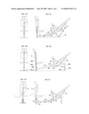
[0011]FIG. 1A is a side view of a configuration of the present invention having a second seat carriage supported by an adjustably inclinable longitudinal support rail, and a separately inclinable first seat.
[0012]FIG. 1B is a side view of a configuration of the present invention having an adjustably inclinable frame supporting both first and second seats.
[0013]FIG. 1C is a side view of a configuration of the present invention having a fixed track and inclinable front seat.
[0014]FIG. 2 is a side view of a configuration of the present invention having an elevating second seat on a horizontal or inclined track.
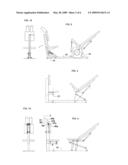
[0015]FIG. 3 is a schematic side view of a configuration of the present invention having a pivoting support for the second seat means
[0016]FIG. 4 is a schematic side view of a configuration of the present invention having dual pivoting arm supports for second seat means.
[0017]FIG. 5A is a schematic side view of a therapist applying foot pressure to a patient's torso using the device and method of the present invention.
[0018]FIG. 5B is a schematic side view of footrests added to the embodiment of FIG. 5A or 6A.
[0019]FIG. 6A is a schematic side view of a therapist applying hand pressure to patients torso using the device and method of the present invention.
[0020]FIG. 6B is a schematic side view of knee-rests added to the embodiment of FIG. 5A or 6A.
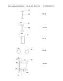
[0021]FIG. 7A is a cross section of an I-beam track and carriage having friction plate adjusting means.
[0022]FIGS. 7B, 7C, 7D, and 7E are side views of friction plate adjusting means.
[0023]FIG. 7F is an end view of a track and carriage having horizontally oriented friction plate adjusting means.
[0024]FIGS. 8A through 8E are cross-sectional end views of various track configurations.
[0025]FIGS. 9A through 9D are side views of viscoelastic damping means.
[0026]FIG. 11A is and end view of the first seat pictured in FIG. 1A.
[0027]FIG. 11B is and end view of the first seat pictured in FIG. 1B.
[0028]FIG. 11C is and end view of the first seat pictured in FIG. 1C.
[0029]FIG. 12 is and end view of the first seat pictured in FIG. 2.
[0030]FIG. 14 is and end view of the first seat pictured in FIG. 4.
DESCRIPTION OF THE PRESENT INVENTION
[0031]The invention as disclosed in the drawings and the claims provides for the tandem seating of patient and therapist.
[0032]In FIGS. 5A and 6A, patient 10 sits on first seat 1 supported by first lateral rest 2 which may include head rest means 3 in rigid fixed or adjustable proximity thereto.
[0033]In FIG. 11C, first seat 1 preferably includes vertical adjusting means, preferably aided by vertical gas cylinder 4, preferably having hydraulic release lever 5 extending from upper end of cylinder. First seat preferably includes means for angular adjustment about a pivot point 6 between seat 1 and cylinder 4 as in FIG. 1A or FIG. 4, or between cylinder 4a and support frame 15, as in FIG. 1C. Lateral rest 8 may include separate adjusting means about separate pivot point 6a as in FIG. 4, and headrest means 3 preferably includes separate adjusting means about headrest pivot 6b.
[0034]In FIGS. 5A and 6A, therapist 11 is supported by second seat 7 and second lateral rest 8, both of which may be adjusted laterally toward or away from patient by adjusting means 9, and which may be further adjusted by seat and lateral angular adjusting means 12 and 13, as in FIGS. 1A, 1B, and 1C.
[0035]In FIG. 1B common framework 15, in combination with said lateral supports and adjusting means hold the two occupants in fixed position. Substantially vertical sleeves 15a and 15b receive first and second vertical legs 14a and 14b, extending from horizontal foot means 14c and 14d. First leg 14a extends into first chair sleeve 14e. Vertical adjusting means 4, preferably in the form of a pneumatic cylinder inside first leg means 14a, allows vertical adjustment of first scat with minimal leg effort by patient.
[0036]Second seat is preferably supported by carriage means 21, preferably constrained by wheel means 22 on track means 16 extending longitudially along an axis substantially parallel to an axis extending between first and second seats.
[0037]Second seat and lateral rest means may also optionally be adjustable vertically by second vertical adjusting means 14b, which may lift just the second seat as in FIG. 4, or lift an end of support rail 16 as in FIG. 1A, or lift the entire end of common framework 15 supporting both first and second seat, as in FIG. 1B, thereby adjusting the angle of front seat and track simultaneously.
[0038]Lateral or angular or vertical adjusting means may be by any suitable mechanism, including hydraulic cylinders, stacked plate spring clamps, jack screws, or simple slides and locking screws, preferably assisted by force means such as springs or gas cylinders.
[0039]Force means 17, for instance gravity, spring, or gas cylinder or combination thereof, urges second seat means 7 preferably toward first seat means, opposed by positioning leg effort by therapist. Preferably damping means 18 attached to second seat, for instance a hydraulic cylinder, prevents rapid motion of said second seat when unrestrained by user or locking means.
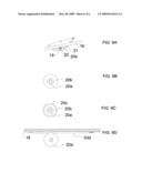
[0040]A preferred embodiment of damping means 18 in FIG. 9A comprises a viscoelastic wheel means 19, the axis of which travels in slot or track 20s, oblique to carriage means 21 holding second seat means 7, and riding on track means 16, tightening or loosening said wheel against said track means 16 depending on the direction of travel of said carriage means.
[0041]Alternatively said wheel axis may pivot on eccentric lever means 20. Lever arm of said eccentric is sharply obique to the track surface, pivoting in such a manner that motion of carriage means 21 in the direction of force means 17 causes lever 20 to rotate to tighten said viscoelastic wheel against track, creating a damping force resisting linear motion, while motion in opposite direction rotates lever to loosen said wheel. Spring or other means is used to urge wheel against track when not forcefully engaged by eccentric.
[0042]Said viscoelastic wheel may have rigid core means 20a and viscoelastic outer tire 20b, as in FIG. 9B.
[0043]Alternatively said viscoelastic wheel may preferably have rigid core means 20a and rigid outer tire 20c with viscoelastic material 20b in the anulus therebetween, as in FIG. 9C.
[0044]Alternatively said tire may be of rigid material riding on a viscoelastic track surface, preferably in the form of an elastomer-coated preferably flat bar or cable 20d pulled taught by its ends along the path of said wheel, if FIG. 9D.
[0045]In FIGS. 7A and 7B said carriage means preferably comprises opposing members 21A and 211B, stradling I-beam rail means 16. Opposed clamping means (for instance solid bars) 30a and 30b pulled together by tie rod means 31A and 31B, preferably above and below track 16, in combination with spring means 37 apply pressure to opposing piston means 34, which in turn apply pressure normal to surfaces of interleaving fixed longitudinal friction plates 32 and movable friction plates 33 attached flexibly to carriage 21 by anchor means 35.
[0046]Release handle 39, preferably coaxial with spring means 37 on tie rod 31A rigidly connects to preferably domed lever means 38 which functionally engages shoulder means 31C and clamp means 30 to force clamps 30a and 30b apart with mechanical advantage when force is applied to handle 39 in preferably any direction, thereby relieving pressure on friction plates 32 and 33.
[0047]FIGS. 7C and 7D shows typical friction means used for angular adjustment of first or second seat or lateral supports or headrest means. Preferably slotted friction plates 42 having slot 45 and one or more anchor means 46 in a stack penetrated by tie rod 41 are pressed in friction engagement with interleaving friction plates 43 in the form of washers in FIGS. 7C and 7D or plates pivoting plates 47 in FIG. 7E.
[0048]Track means 16 is preferably a monorail, and may be for example a box as in FIG. 8C or an I shape as in FIG. 8A or 8B. Alternatively, track means may comprise multiple rails, for instance twin horizontal rails shown in FIG. 8D, or preferably an extruded or formed cross section of any appropriate shape as in FIG. 8E. Web means 16b extending from bottom of rail 16, in FIG. 8E may serve as a support for a stack of longitudinal friction plates, which may be penetrated by a tie rod slot, or it may utilize c-clamp means or dual tie rod means for clamping as in FIG. 8Aa.
[0049]Track means 16 preferably includes support surfaces 16b and 16c by which guides or wheels mounted to carriage means support said carriage in fixed orientation to said track means. Wheels may have lateral support means, such as flanged wheels 22b. The preferred embodiment employs simple low-friction polymer skid plate means 22c, constrained from planar displacement by loose engagement with axles, tie rods, or standoffs, and attached preferably to said carriage means, and engaging carriage and track means in lateral alignment of carriage to said track means. Carriage may then preferably use simple bearing means or cylindrical wheel means 22a as shown for vertical support and alignment.
[0050]A preferred track and carriage combination in FIG. 7F includes track means 16 having a substantial horizontal surface 16b engaging linear bearing means 22d, preferably in the form of a continuous ball race, which provides vertical support for said carriage means 21.
[0051]A preferred track configuration has a concavity in lower surface concealing adjusting means and/or damping means. Adjustment locking means may be, for example, a valved cylinder as shown in previous figures, or as shown in FIG. 7F, a stacked plate set having a single tie rod 31 through slot in fixed plates 32s and hole in moving plate 33s functionally attached to said carriage. Track means preferably has tubular component or components 16e to resist torsion.
[0052]An alternative adjusting mechanism for the headrest includes two stacks of interleaving plates 47a and 47b compressed by tie rod 41 at headrest pivot axis 6b, and rotationally fixed to support and headrest means by anchor means 46a and 46b.
[0053]Anchor means 35, 36, and 46 may be any means resisting linear displacement of a plate parallel to its surface, but are preferably cylindrical means such as a pin or shoulder bolt, through a loosely fitting hole in said plate.
[0054]An advantage of clamp bars 30 is that it avoids weakening track 16 with a slot, and it multiplies the force of spring means 37 through mechanical advantage to the friction plates, as compared to slotted plates penetrated by a single sprung tie rod.
[0055]An alternative embodiment may include fixed, adjustable, or retractable footrest means 50 or knee rest means 51, as in FIGS. 5B and 6B for either occupant.
[0056]Seats and lateral rests preferably include padded upholstery.
[0057]In FIG. 3, either of first or second seats may be contoured to enhance comfort, and swivel means 40 about a vertical axis may be provided for one or both seats to enhance comfort when the seating position of one or both occupants is reversed.
[0058]The therapist applies hand or foot pressure, or a combination thereof, to the patient. In applying foot pressure to massage a back, the therapist avoids fatigue and repetitive stress injury to hands, wrists, and arms by utilizing the larger and more durable muscles and joints of the legs and feet. Further, the back support provided to the therapist during manipulation is not found in other massage chairs, and reduces spinal and abdominal exertion and fatigue.
[0059]Vertical adjustment means 4 and 5 enable patient in first seat to adjust his own vertical position during therapy, thereby directing and assisting in his own therapy.
[0060]Carriage may travel freely along track during therapy or remain in fixed adjusted position relative to first occupant. Device may include separate therapeutic pressure limiting means, for example a relief valve on a cylinder controlling horizontal motion.
[0061]The description and illustrations enclosed herein are merely schematic examples of the claimed invention. Obvious modifications which might facilitate use for intimate contact are included within the scope of the present invention. Deviations from the configurations described herein which may be obvious to those skilled in the art, fall within the scope of this invention, as does the described method of providing massage therapy from a tandem seated position using furniture providing adequate support.
Claims:
1. A chair configuration consisting in first and second chair means
providing for the tandem seating of two occupants, one in front of the
other, each chair means having surface means applying a combination of
vertical and horizontal support to its occupant, and further having
connective structural means resisting with substantial rigidity the force
and moment created by substantially horizontal hand or foot pressure by
one occupant upon the body of the other.
2) An assembly as described in claim 1 and further comprising means to move or adjust at least one of said chair means in a substantially vertical direction and means to move or adjust at least one of said chairs in a substantially horizontal direction, and providing means to position said chairs relative to each other to locate the occupants advantageously for ease of application of foot or hand pressure by one occupant to the other.
3) An assembly as described in claim 2 wherein said substantially horizontal adjustment means optionally includes a track, supporting a slide or roller trolley means, which supports the second seat bottom and rear body rest, and wherein said substantially horizontal track may optionally be mounted at an incline causing said second chair means to elevate as it moves rearward under foot or hand power, and to return forward under the force of gravity.
4) An assembly as described in claim 2 wherein said substantially horizontal adjustment means optionally may alternatively include one or more pivoting legs forming a substantially horizontal front to rear arcuate path for the rear chair, and optionally including spring means, causing the rear chair to return forward when human force is removed and adjustment means is unlocked.
5) An assembly as described in claim 2 wherein said chair and structural means includes first and second seating means providing substantially vertical support, and separately one or both of a first and second body rests supporting the upper body of its occupant.
6) An assembly as described in claim 5 wherein said body rests optionally include integrally or separately head rest or face rest means.
7) An assembly as described in claim 6 and further optionally including lockable inclination adjusting means on at least one body rest to accommodate a range of positions, facilitating application by one occupant of hand or feet to the body of the other occupant, and facilitating comfortable positioning for a range of occupant sizes.
8) An assembly as described in claim 7 and further optionally including separate inclination adjusting means on at least one of the two seat bottoms.
9) An assembly as described in claim 1 wherein at least one of said adjustment means includes mechanical or pneumatic spring means, which return the adjustable member to its relaxed position when said adjustment means is unlocked and occupant force against said member is relaxed, and further optionally including locking means to secure the position of said member.
10) An assembly as described in claim 9 wherein optionally at least one of said adjustment means includes a damping means opposing the rapid travel of the adjusted member due to the forces of gravity or spring means.
11) An assembly as described in claim 9 wherein optionally at least one of the seatbottoms is attached at a fixed angle with substantial rigidity to its respective body rest.
12) An assembly as described in claim 11 wherein the front body rest is configured in a position and shape to support the torso of the front occupant whether facing away from or toward the rear occupant.
13) A method of delivering therapy by supporting a patient in front of a therapist supported in seated or recumbent position on apparatus as described in claim 1, the therapist applying hand or foot pressure to the patient.
14) A device as described in claim 3, including wheel means compressed against track means during travel in one or both directions by suitable mechanical means, wherein one or both of said wheel and track means includes an elastomeric component, and wherein travel of wheel along track means flexes elastomeric component in an energy absorbing manner.
15) A device as described in claim 3 wherein substantially vertical sleeve means is secured to one or both ends of said track means, and receives in sliding fit tubular leg means extending from substantially horizontal foot means.
16) A device as described in claim 15 wherein leg mean situated under first seat extends through said sleeve means vertically, and further supports in sliding fit sleeve means mounted to first chair means.
17) A device as described in claim 1, wherein said first chair means provides vertical and lateral support for first occupant whether facing away from second occupant or toward second occupant.
18) A device as described in claim 1 and further including foot rest means or knee rest means for one or both occupants.
Description:
[0001]This application claims priority of provisional application 60998759
filed Oct. 13, 2007.
FIELD OF INVENTION
[0002]The present invention relates to therapeutic furniture and apparatus. In particular, the present invention relates to touch therapy-facilitating furniture adapted to support both patient and therapist in a tandem configuration.
BACKGROUND
[0003]Tables and chairs, typified by U.S. Pat. Nos. 6,934,988 and 4,662,361, are known for the support of patients during delivery of physical therapy in the form of manual massage by a therapist. Those tables and chairs have the disadvantages of 1) fatigue and repetitive stress injury to the therapist's hands and limbs, and 2) fatigue to the torso of the therapist from leaning over the patient.
SUMMARY
[0004]The present invention avoids the disadvantages of the prior art by presenting the patient to a seated or recumbent therapist in such a manner that the therapist may use the stronger and more fatigue resistant muscles of the feet, legs, and thighs in delivering therapy to the patient The structure disclosed also reduces back and abdominal fatigue to the therapist during manipulation by supporting the torso of the therapist.
OBJECTS
[0005]An object of the present invention is to reduce fatigue and repetitive stress injury to the hands, wrists, arms and upper body of the therapist.
[0006]An additional object of the present invention is to reduce fatigue to the back and torso of the therapist by supporting the therapist in a comfortable reclining position during the therapy.
[0007]An additional object of the present invention is that the duration of therapy may be longer and more effective before the therapist is fatigued.
[0008]An additional object of the present invention is that a therapist, even one with low upper body strength, may deliver therapy at a high energy level.
[0009]An additional object of the present invention is that a therapist may obtain exercise benefits by working large long muscles over a longer time period to burn a greater number of calories than would be possible by using the muscles of the upper body.
[0010]An additional object of the invention is to enable the patient to assist in directing his own therapy.
DRAWINGS
[0011]FIG. 1A is a side view of a configuration of the present invention having a second seat carriage supported by an adjustably inclinable longitudinal support rail, and a separately inclinable first seat.
[0012]FIG. 1B is a side view of a configuration of the present invention having an adjustably inclinable frame supporting both first and second seats.
[0013]FIG. 1C is a side view of a configuration of the present invention having a fixed track and inclinable front seat.
[0014]FIG. 2 is a side view of a configuration of the present invention having an elevating second seat on a horizontal or inclined track.
[0015]FIG. 3 is a schematic side view of a configuration of the present invention having a pivoting support for the second seat means
[0016]FIG. 4 is a schematic side view of a configuration of the present invention having dual pivoting arm supports for second seat means.
[0017]FIG. 5A is a schematic side view of a therapist applying foot pressure to a patient's torso using the device and method of the present invention.
[0018]FIG. 5B is a schematic side view of footrests added to the embodiment of FIG. 5A or 6A.
[0019]FIG. 6A is a schematic side view of a therapist applying hand pressure to patients torso using the device and method of the present invention.
[0020]FIG. 6B is a schematic side view of knee-rests added to the embodiment of FIG. 5A or 6A.
[0021]FIG. 7A is a cross section of an I-beam track and carriage having friction plate adjusting means.
[0022]FIGS. 7B, 7C, 7D, and 7E are side views of friction plate adjusting means.
[0023]FIG. 7F is an end view of a track and carriage having horizontally oriented friction plate adjusting means.
[0024]FIGS. 8A through 8E are cross-sectional end views of various track configurations.
[0025]FIGS. 9A through 9D are side views of viscoelastic damping means.
[0026]FIG. 11A is and end view of the first seat pictured in FIG. 1A.
[0027]FIG. 11B is and end view of the first seat pictured in FIG. 1B.
[0028]FIG. 11C is and end view of the first seat pictured in FIG. 1C.
[0029]FIG. 12 is and end view of the first seat pictured in FIG. 2.
[0030]FIG. 14 is and end view of the first seat pictured in FIG. 4.
DESCRIPTION OF THE PRESENT INVENTION
[0031]The invention as disclosed in the drawings and the claims provides for the tandem seating of patient and therapist.
[0032]In FIGS. 5A and 6A, patient 10 sits on first seat 1 supported by first lateral rest 2 which may include head rest means 3 in rigid fixed or adjustable proximity thereto.
[0033]In FIG. 11C, first seat 1 preferably includes vertical adjusting means, preferably aided by vertical gas cylinder 4, preferably having hydraulic release lever 5 extending from upper end of cylinder. First seat preferably includes means for angular adjustment about a pivot point 6 between seat 1 and cylinder 4 as in FIG. 1A or FIG. 4, or between cylinder 4a and support frame 15, as in FIG. 1C. Lateral rest 8 may include separate adjusting means about separate pivot point 6a as in FIG. 4, and headrest means 3 preferably includes separate adjusting means about headrest pivot 6b.
[0034]In FIGS. 5A and 6A, therapist 11 is supported by second seat 7 and second lateral rest 8, both of which may be adjusted laterally toward or away from patient by adjusting means 9, and which may be further adjusted by seat and lateral angular adjusting means 12 and 13, as in FIGS. 1A, 1B, and 1C.
[0035]In FIG. 1B common framework 15, in combination with said lateral supports and adjusting means hold the two occupants in fixed position. Substantially vertical sleeves 15a and 15b receive first and second vertical legs 14a and 14b, extending from horizontal foot means 14c and 14d. First leg 14a extends into first chair sleeve 14e. Vertical adjusting means 4, preferably in the form of a pneumatic cylinder inside first leg means 14a, allows vertical adjustment of first scat with minimal leg effort by patient.
[0036]Second seat is preferably supported by carriage means 21, preferably constrained by wheel means 22 on track means 16 extending longitudially along an axis substantially parallel to an axis extending between first and second seats.
[0037]Second seat and lateral rest means may also optionally be adjustable vertically by second vertical adjusting means 14b, which may lift just the second seat as in FIG. 4, or lift an end of support rail 16 as in FIG. 1A, or lift the entire end of common framework 15 supporting both first and second seat, as in FIG. 1B, thereby adjusting the angle of front seat and track simultaneously.
[0038]Lateral or angular or vertical adjusting means may be by any suitable mechanism, including hydraulic cylinders, stacked plate spring clamps, jack screws, or simple slides and locking screws, preferably assisted by force means such as springs or gas cylinders.
[0039]Force means 17, for instance gravity, spring, or gas cylinder or combination thereof, urges second seat means 7 preferably toward first seat means, opposed by positioning leg effort by therapist. Preferably damping means 18 attached to second seat, for instance a hydraulic cylinder, prevents rapid motion of said second seat when unrestrained by user or locking means.
[0040]A preferred embodiment of damping means 18 in FIG. 9A comprises a viscoelastic wheel means 19, the axis of which travels in slot or track 20s, oblique to carriage means 21 holding second seat means 7, and riding on track means 16, tightening or loosening said wheel against said track means 16 depending on the direction of travel of said carriage means.
[0041]Alternatively said wheel axis may pivot on eccentric lever means 20. Lever arm of said eccentric is sharply obique to the track surface, pivoting in such a manner that motion of carriage means 21 in the direction of force means 17 causes lever 20 to rotate to tighten said viscoelastic wheel against track, creating a damping force resisting linear motion, while motion in opposite direction rotates lever to loosen said wheel. Spring or other means is used to urge wheel against track when not forcefully engaged by eccentric.
[0042]Said viscoelastic wheel may have rigid core means 20a and viscoelastic outer tire 20b, as in FIG. 9B.
[0043]Alternatively said viscoelastic wheel may preferably have rigid core means 20a and rigid outer tire 20c with viscoelastic material 20b in the anulus therebetween, as in FIG. 9C.
[0044]Alternatively said tire may be of rigid material riding on a viscoelastic track surface, preferably in the form of an elastomer-coated preferably flat bar or cable 20d pulled taught by its ends along the path of said wheel, if FIG. 9D.
[0045]In FIGS. 7A and 7B said carriage means preferably comprises opposing members 21A and 211B, stradling I-beam rail means 16. Opposed clamping means (for instance solid bars) 30a and 30b pulled together by tie rod means 31A and 31B, preferably above and below track 16, in combination with spring means 37 apply pressure to opposing piston means 34, which in turn apply pressure normal to surfaces of interleaving fixed longitudinal friction plates 32 and movable friction plates 33 attached flexibly to carriage 21 by anchor means 35.
[0046]Release handle 39, preferably coaxial with spring means 37 on tie rod 31A rigidly connects to preferably domed lever means 38 which functionally engages shoulder means 31C and clamp means 30 to force clamps 30a and 30b apart with mechanical advantage when force is applied to handle 39 in preferably any direction, thereby relieving pressure on friction plates 32 and 33.
[0047]FIGS. 7C and 7D shows typical friction means used for angular adjustment of first or second seat or lateral supports or headrest means. Preferably slotted friction plates 42 having slot 45 and one or more anchor means 46 in a stack penetrated by tie rod 41 are pressed in friction engagement with interleaving friction plates 43 in the form of washers in FIGS. 7C and 7D or plates pivoting plates 47 in FIG. 7E.
[0048]Track means 16 is preferably a monorail, and may be for example a box as in FIG. 8C or an I shape as in FIG. 8A or 8B. Alternatively, track means may comprise multiple rails, for instance twin horizontal rails shown in FIG. 8D, or preferably an extruded or formed cross section of any appropriate shape as in FIG. 8E. Web means 16b extending from bottom of rail 16, in FIG. 8E may serve as a support for a stack of longitudinal friction plates, which may be penetrated by a tie rod slot, or it may utilize c-clamp means or dual tie rod means for clamping as in FIG. 8Aa.
[0049]Track means 16 preferably includes support surfaces 16b and 16c by which guides or wheels mounted to carriage means support said carriage in fixed orientation to said track means. Wheels may have lateral support means, such as flanged wheels 22b. The preferred embodiment employs simple low-friction polymer skid plate means 22c, constrained from planar displacement by loose engagement with axles, tie rods, or standoffs, and attached preferably to said carriage means, and engaging carriage and track means in lateral alignment of carriage to said track means. Carriage may then preferably use simple bearing means or cylindrical wheel means 22a as shown for vertical support and alignment.
[0050]A preferred track and carriage combination in FIG. 7F includes track means 16 having a substantial horizontal surface 16b engaging linear bearing means 22d, preferably in the form of a continuous ball race, which provides vertical support for said carriage means 21.
[0051]A preferred track configuration has a concavity in lower surface concealing adjusting means and/or damping means. Adjustment locking means may be, for example, a valved cylinder as shown in previous figures, or as shown in FIG. 7F, a stacked plate set having a single tie rod 31 through slot in fixed plates 32s and hole in moving plate 33s functionally attached to said carriage. Track means preferably has tubular component or components 16e to resist torsion.
[0052]An alternative adjusting mechanism for the headrest includes two stacks of interleaving plates 47a and 47b compressed by tie rod 41 at headrest pivot axis 6b, and rotationally fixed to support and headrest means by anchor means 46a and 46b.
[0053]Anchor means 35, 36, and 46 may be any means resisting linear displacement of a plate parallel to its surface, but are preferably cylindrical means such as a pin or shoulder bolt, through a loosely fitting hole in said plate.
[0054]An advantage of clamp bars 30 is that it avoids weakening track 16 with a slot, and it multiplies the force of spring means 37 through mechanical advantage to the friction plates, as compared to slotted plates penetrated by a single sprung tie rod.
[0055]An alternative embodiment may include fixed, adjustable, or retractable footrest means 50 or knee rest means 51, as in FIGS. 5B and 6B for either occupant.
[0056]Seats and lateral rests preferably include padded upholstery.
[0057]In FIG. 3, either of first or second seats may be contoured to enhance comfort, and swivel means 40 about a vertical axis may be provided for one or both seats to enhance comfort when the seating position of one or both occupants is reversed.
[0058]The therapist applies hand or foot pressure, or a combination thereof, to the patient. In applying foot pressure to massage a back, the therapist avoids fatigue and repetitive stress injury to hands, wrists, and arms by utilizing the larger and more durable muscles and joints of the legs and feet. Further, the back support provided to the therapist during manipulation is not found in other massage chairs, and reduces spinal and abdominal exertion and fatigue.
[0059]Vertical adjustment means 4 and 5 enable patient in first seat to adjust his own vertical position during therapy, thereby directing and assisting in his own therapy.
[0060]Carriage may travel freely along track during therapy or remain in fixed adjusted position relative to first occupant. Device may include separate therapeutic pressure limiting means, for example a relief valve on a cylinder controlling horizontal motion.
[0061]The description and illustrations enclosed herein are merely schematic examples of the claimed invention. Obvious modifications which might facilitate use for intimate contact are included within the scope of the present invention. Deviations from the configurations described herein which may be obvious to those skilled in the art, fall within the scope of this invention, as does the described method of providing massage therapy from a tandem seated position using furniture providing adequate support.
User Contributions:
Comment about this patent or add new information about this topic:
| People who visited this patent also read: | |
| Patent application number | Title |
|---|---|
| 20190211058 | COMPOUNDS FOR PROTEASOME ENZYME INHIBITION |
| 20190211057 | TARGETED PRODRUG ENZYME FUSION CARRIER AND APPLICATION THEREOF |
| 20190211056 | METHOD FOR PURIFYING PROTEIN USING ACTIVATED CARBON |
| 20190211055 | METHODS OF PURIFYING AND QUALIFYING ANTIBODIES |
| 20190211054 | 19-NOR NEUROACTIVE STEROIDS AND METHODS OF USE THEREOF |
Images included with this patent application:
 |  |
 |  |
 |  |
 |
| Similar patent applications: | |
| Date | Title |
|---|---|
| 2010-01-07 | Therapeutic back support and stabilization |
| 2010-07-01 | Ergonomic supporting/sitting device |
| 2011-04-28 | Head supporting device |
| 2011-08-18 | Personal support device |
| 2009-08-13 | Manuel adjustment of a back support on a vehicle |
| New patent applications in this class: | |
| Date | Title |
|---|---|
| 2016-05-05 | Collapsible portable structures that convert to articles of furniture when filled with sand |
| 2016-02-18 | Vehicle seat with integrated child seat |
| 2015-11-26 | Convertible child seat |
| 2015-10-15 | Reconfigurable infant support structure |
| 2015-03-26 | Configurable seating assembly |
| New patent applications from these inventors: | |
| Date | Title |
|---|---|
| 2015-03-19 | Stringed instrument improvement |
| 2010-03-18 | Stringed instrument improvement |
| Top Inventors for class "Chairs and seats" | |
| Rank | Inventor's name |
|---|---|
| 1 | Johnathan Andrew Line |
| 2 | Larry P. Lapointe |
| 3 | Yukifumi Yamada |
| 4 | John W. Jaranson |
| 5 | Erwin Haller |