Patent application title: FLAT CONTAINER
Inventors:
Artur Wichowski (Gerlafingen, CH)
Assignees:
Hoffmann Neopac AG
IPC8 Class: AB65D5104FI
USPC Class:
220810
Class name: Receptacles closures pivotable, (e.g., hinged)
Publication date: 2009-05-28
Patent application number: 20090134178
a container bottom (3) is provided having a
peripheral edge (3') in which a step (13) is formed. A film (19) with a
peel-away tab (21)is sealed or bonded to the step. Under the film (19)
that advantageously has an air-tight and water vapor-tight construction,
an optimum product space (23) for the product can be obtained.Claims:
1. A flat container (1) comprising a container top (3) and a container
bottom (5) that are connected to each other in an articulated way by at
least one hinge (7), on the container bottom (3) a peripheral step (13)
is constructed at the top of the container bottom as a sealing surface
(15) for a sealing a film (19) to form an air-tight seal of a filling
space (23) in the container bottom (3).
2. The flat container according to claim 1, wherein the peripheral step (13) is formed by a peripheral bead directed inwardly on the container bottom (3).
3. The flat container according to claim 1, wherein a sealing surface (15) of the step (13) is arranged at a distance to a peak S on a top edge of the container bottom.
4. The flat container according to claim 3, wherein an adhesive is applied on the sealing surface (15) of the step (13) or that an inside of the lower container part (3) and the bottom side of the film (19) are coated with a sealable coating.
5. The flat container according to claim 3, wherein the step (13) that forms the sealing surface (15) lies essentially completely within a side wall (3'') of the container (1).
6. The flat container according to claim 5, wherein outside of the sealing surface (15), a peripheral edge (31) is attached and is adapted to contact the cover part (5) and to center the film (19).
7. The flat container according to claim 1, wherein a central part (25) of the upper container part (5) is lowered.
8. The flat container according to claim 7, wherein, for a closed container (1), the central part (25) of the upper container (5) lies at a small distance from the film or contacts the film.Description:
CROSS-REFERENCE TO RELATED APPLICATIONS
[0001]This application claims the benefit of Swiss Patent Application Nos. 01821/07, filed Nov. 26, 2007 and 01650/08, filed Oct. 17, 2008, both of which are incorporated by reference herein as if fully set forth.
BACKGROUND
[0002]The invention is directed to a flat container for cigarettes, cigars, sweets, and the like.
[0003]Expensive cigarettes, cigars, cigarillos, and the like, but also sweets are often sold in sheet-metal containers, because, on one hand, they can be stored in these containers protected against damage and, on the other hand, a high degree of air and water-vapor tightness is guaranteed up until the first opening. Tightness is a problem because the closing of sheet-metal containers with hinged covers is difficult, which is why the goods are often sealed, for example, in aluminum foil or a laminate film and only then placed in the box.
SUMMARY
[0004]One object of the present invention lies in sealing the bottom part of the container, i.e., the container bottom, in which lie the goods (cigarettes, cigars, etc.), as tight as possible against air and water vapor. Another objective of the invention is allowing the closure creating the air and water-vapor tightness to be removed from the container bottom without a tool.
[0005]These objectives are met by a container according to the invention. Advantageous configurations of the container are described below and in the claims.
[0006]Through a suitable shaping of the container bottom, a film or membrane can be bonded or sealed to the bottom. The sealing surface is here formed by a step with a shoulder that gives a sufficiently large bonding surface between the membrane and container bottom. The sealing of the membrane after the container bottom is filled with the goods to be stored can be performed in a very simple way by a heated stamp. Through the full surface contact of the container bottom on a support surface, the sealing heat can be optimally transferred and thus the product can be protected from heat. Also here, the container bottom is not deformed. The shaping of the sealing surface according to the invention permits a precise centering of the sealing membrane completely in the interior of the lidded container or case. The detachment/peeling off of the membrane is easily possible by hand without the aid of tools. Here, the entire container cross-sectional surface is left free from residue. The container can also be produced cost-effectively by a deep-drawing process and is completely recyclable after being emptied, because no plastic parts are connected to the container.
BRIEF DESCRIPTION OF THE DRAWINGS
[0007]The invention will be explained in more detail with reference to an illustrated embodiment. Shown are:
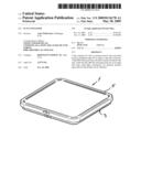
[0008]FIG. 1 is a perspective view of a closed container with a container bottom and a container top,
[0009]FIG. 2 is a perspective view of the container according to FIG. 1, with the front halt cut away,
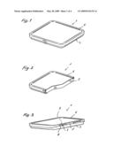
[0010]FIG. 3 is a perspective view of the container viewed from behind,
[0011]FIG. 4 is a perspective view of the opened container with partially detached closure membrane,
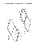
[0012]FIG. 5 is a perspective view of the opened container, membrane removed,
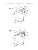
[0013]FIG. 6 is an enlarged cross sectional view through the rear edge region of the container without sealed film,
[0014]FIG. 7 is an enlarged cross sectional view through the rear edge region of the container with sealed film,
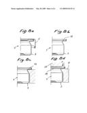
[0015]FIG. 8a is a partial cross sectional view through another construction of the container bottom with container top placed on top,
[0016]FIG. 8b is a partial cross sectional view through the container bottom in FIG. 8a without cover,
[0017]FIG. 8c is a partial cross sectional view through the container with retracted sealing surface, and
[0018]FIG. 8d is a partial cross sectional view through the container with retracted sealing surface and heating tool acting from above.
DETAILED DESCRIPTION OF THE PREFERRED EMBODIMENTS
[0019]In the figures, a container is designated with reference symbol 1, that comprises a container bottom 3 and a container top 5. Both the container bottom 3 and also the container top 5 have peripheral side walls 3' and 3'' or 5' and 5''. The two container parts 3, 5 are connected to each other by hinges 7. The hinges 7 are formed by suitably shaped clips on the edges of the container bottom and top. On the container top 5, in one side wall 5'' in the present example two rectangular recesses 9 that run parallel to the edges are stamped out. Clips 11 that are part of the side wall 3'' engage in the two recesses 9 and are generated by a shaping process (bending/rolling). The container bottom 3 is consequently not pierced by stamped-out sections and the like. In the upper region of the side walls 3' and 3'' of the container bottom 3, a projection-shaped step 13 directed inwardly is formed by a deformation process. On the step 13, the upper surface 15 runs parallel to the base 17 and the free top edge (peak S) of the container bottom 3. The surface 15 extends along the entire periphery of the container bottom 3 (compare, in particular, FIGS. 6 and 7). The surface 15 lies at a vertical distance from the peak S of the side walls 3' and 3'', i.e., the surface is spaced apart from the top edge. It thus forms a peripheral strip-shaped, planar contact for a membrane or film 19 (FIG. 7). The latter is held by an adhesive on the step 13 so that it can be peeled off. A hot melt can be used as the adhesive or the inner surface of the lower container part 3 is coated with a sealable coating (a PE, PVC, or PP-containing coating) just like the bottom side of the film 19. In order to be able to easily peel the film 19 from the step 13, the adhesive must be peelable on one side and on the film 19, a tab 21 is formed that projects upwards and can be easily gripped with two fingers after the film 19 is sealed on the step 13.
[0020]The application of the sealing film 19 on the step 13 after filling the goods (cigarettes, cigarillos, and the like) can be realized in a very simple way with a heated sealing tool following the contours of the step 13 or by ultrasonic welding. The support of the sealing pressure can be realized in a simple way from the outside. In addition, the heat generated by the sealing is far away from the product. Because there are no stamped-out sections, recesses, or the like in the lower container part 3, the product space 23 under the film 19 is sealed tight against air and water vapor after the sealing and guarantees optimum conditions for the product.
[0021]In the configuration of the container 1 according to FIGS. 8a to 8d, a wide step is formed, in turn, as the sealing surface on the container bottom 3. The connection between the container bottom 3 and the cover 5 is here not shown in more detail; it can be realized, in turn, by a hinge according to FIGS. 6 and 7 or in other ways.
[0022]In order to obtain a trouble-free seal connection between the film 19 and the step 13 (the sealing surface), during the sealing process a support device 27 that engages under the step 13 is led under the step 13. Advantageously, the support device 27 is constructed in such a way that it contacts the entire surface of at least the bottom of the step 13. With a sealing tool 29 that extends, in turn, across the entire width of the step 13, an optimum total surface contact between the step 13, film 19, and the sealing tool 29 can be obtained, without the container bottom 3 having to absorb axial forces F.
[0023]In addition, the temperature T generated by the sealing tool 29 is dissipated in the sealing region directly through the support device 27. In this way, a negative effect on the product by a temperature increase in the edge region of the container 1 is prevented.
[0024]On the container top 5, the surface between the edges 5' and 5'' is advantageously lowered by a deep-drawing process, i.e., the central region of the container top lies lower than its edge. From FIG. 6 it is easily evident that the central part 25 runs parallel to the film 19 and lies at a very small distance or at no distance from this film. Through this measure, the usually very thin film 19 is protected against damage by the product in the filling space 23, when the container 1 is, e.g., dropped. In other words, a significantly thinner film 19 can be used, because this is exposed to no mechanical loading.
Legend
[0025]1 Container
[0026]3 Container bottom
[0027]5 Container top
[0028]7 Hinge
[0029]9 Recesses
[0030]11 Clips
[0031]13 Step
[0032]15 Sealing surface
[0033]17 Base
[0034]19 Film
[0035]21 Tab
[0036]23 Product space
[0037]25 Central part of 3
[0038]27 Support device
[0039]29 Sealing tool
[0040]31 Peripheral edge
Claims:
1. A flat container (1) comprising a container top (3) and a container
bottom (5) that are connected to each other in an articulated way by at
least one hinge (7), on the container bottom (3) a peripheral step (13)
is constructed at the top of the container bottom as a sealing surface
(15) for a sealing a film (19) to form an air-tight seal of a filling
space (23) in the container bottom (3).
2. The flat container according to claim 1, wherein the peripheral step (13) is formed by a peripheral bead directed inwardly on the container bottom (3).
3. The flat container according to claim 1, wherein a sealing surface (15) of the step (13) is arranged at a distance to a peak S on a top edge of the container bottom.
4. The flat container according to claim 3, wherein an adhesive is applied on the sealing surface (15) of the step (13) or that an inside of the lower container part (3) and the bottom side of the film (19) are coated with a sealable coating.
5. The flat container according to claim 3, wherein the step (13) that forms the sealing surface (15) lies essentially completely within a side wall (3'') of the container (1).
6. The flat container according to claim 5, wherein outside of the sealing surface (15), a peripheral edge (31) is attached and is adapted to contact the cover part (5) and to center the film (19).
7. The flat container according to claim 1, wherein a central part (25) of the upper container part (5) is lowered.
8. The flat container according to claim 7, wherein, for a closed container (1), the central part (25) of the upper container (5) lies at a small distance from the film or contacts the film.
Description:
CROSS-REFERENCE TO RELATED APPLICATIONS
[0001]This application claims the benefit of Swiss Patent Application Nos. 01821/07, filed Nov. 26, 2007 and 01650/08, filed Oct. 17, 2008, both of which are incorporated by reference herein as if fully set forth.
BACKGROUND
[0002]The invention is directed to a flat container for cigarettes, cigars, sweets, and the like.
[0003]Expensive cigarettes, cigars, cigarillos, and the like, but also sweets are often sold in sheet-metal containers, because, on one hand, they can be stored in these containers protected against damage and, on the other hand, a high degree of air and water-vapor tightness is guaranteed up until the first opening. Tightness is a problem because the closing of sheet-metal containers with hinged covers is difficult, which is why the goods are often sealed, for example, in aluminum foil or a laminate film and only then placed in the box.
SUMMARY
[0004]One object of the present invention lies in sealing the bottom part of the container, i.e., the container bottom, in which lie the goods (cigarettes, cigars, etc.), as tight as possible against air and water vapor. Another objective of the invention is allowing the closure creating the air and water-vapor tightness to be removed from the container bottom without a tool.
[0005]These objectives are met by a container according to the invention. Advantageous configurations of the container are described below and in the claims.
[0006]Through a suitable shaping of the container bottom, a film or membrane can be bonded or sealed to the bottom. The sealing surface is here formed by a step with a shoulder that gives a sufficiently large bonding surface between the membrane and container bottom. The sealing of the membrane after the container bottom is filled with the goods to be stored can be performed in a very simple way by a heated stamp. Through the full surface contact of the container bottom on a support surface, the sealing heat can be optimally transferred and thus the product can be protected from heat. Also here, the container bottom is not deformed. The shaping of the sealing surface according to the invention permits a precise centering of the sealing membrane completely in the interior of the lidded container or case. The detachment/peeling off of the membrane is easily possible by hand without the aid of tools. Here, the entire container cross-sectional surface is left free from residue. The container can also be produced cost-effectively by a deep-drawing process and is completely recyclable after being emptied, because no plastic parts are connected to the container.
BRIEF DESCRIPTION OF THE DRAWINGS
[0007]The invention will be explained in more detail with reference to an illustrated embodiment. Shown are:
[0008]FIG. 1 is a perspective view of a closed container with a container bottom and a container top,
[0009]FIG. 2 is a perspective view of the container according to FIG. 1, with the front halt cut away,
[0010]FIG. 3 is a perspective view of the container viewed from behind,
[0011]FIG. 4 is a perspective view of the opened container with partially detached closure membrane,
[0012]FIG. 5 is a perspective view of the opened container, membrane removed,
[0013]FIG. 6 is an enlarged cross sectional view through the rear edge region of the container without sealed film,
[0014]FIG. 7 is an enlarged cross sectional view through the rear edge region of the container with sealed film,
[0015]FIG. 8a is a partial cross sectional view through another construction of the container bottom with container top placed on top,
[0016]FIG. 8b is a partial cross sectional view through the container bottom in FIG. 8a without cover,
[0017]FIG. 8c is a partial cross sectional view through the container with retracted sealing surface, and
[0018]FIG. 8d is a partial cross sectional view through the container with retracted sealing surface and heating tool acting from above.
DETAILED DESCRIPTION OF THE PREFERRED EMBODIMENTS
[0019]In the figures, a container is designated with reference symbol 1, that comprises a container bottom 3 and a container top 5. Both the container bottom 3 and also the container top 5 have peripheral side walls 3' and 3'' or 5' and 5''. The two container parts 3, 5 are connected to each other by hinges 7. The hinges 7 are formed by suitably shaped clips on the edges of the container bottom and top. On the container top 5, in one side wall 5'' in the present example two rectangular recesses 9 that run parallel to the edges are stamped out. Clips 11 that are part of the side wall 3'' engage in the two recesses 9 and are generated by a shaping process (bending/rolling). The container bottom 3 is consequently not pierced by stamped-out sections and the like. In the upper region of the side walls 3' and 3'' of the container bottom 3, a projection-shaped step 13 directed inwardly is formed by a deformation process. On the step 13, the upper surface 15 runs parallel to the base 17 and the free top edge (peak S) of the container bottom 3. The surface 15 extends along the entire periphery of the container bottom 3 (compare, in particular, FIGS. 6 and 7). The surface 15 lies at a vertical distance from the peak S of the side walls 3' and 3'', i.e., the surface is spaced apart from the top edge. It thus forms a peripheral strip-shaped, planar contact for a membrane or film 19 (FIG. 7). The latter is held by an adhesive on the step 13 so that it can be peeled off. A hot melt can be used as the adhesive or the inner surface of the lower container part 3 is coated with a sealable coating (a PE, PVC, or PP-containing coating) just like the bottom side of the film 19. In order to be able to easily peel the film 19 from the step 13, the adhesive must be peelable on one side and on the film 19, a tab 21 is formed that projects upwards and can be easily gripped with two fingers after the film 19 is sealed on the step 13.
[0020]The application of the sealing film 19 on the step 13 after filling the goods (cigarettes, cigarillos, and the like) can be realized in a very simple way with a heated sealing tool following the contours of the step 13 or by ultrasonic welding. The support of the sealing pressure can be realized in a simple way from the outside. In addition, the heat generated by the sealing is far away from the product. Because there are no stamped-out sections, recesses, or the like in the lower container part 3, the product space 23 under the film 19 is sealed tight against air and water vapor after the sealing and guarantees optimum conditions for the product.
[0021]In the configuration of the container 1 according to FIGS. 8a to 8d, a wide step is formed, in turn, as the sealing surface on the container bottom 3. The connection between the container bottom 3 and the cover 5 is here not shown in more detail; it can be realized, in turn, by a hinge according to FIGS. 6 and 7 or in other ways.
[0022]In order to obtain a trouble-free seal connection between the film 19 and the step 13 (the sealing surface), during the sealing process a support device 27 that engages under the step 13 is led under the step 13. Advantageously, the support device 27 is constructed in such a way that it contacts the entire surface of at least the bottom of the step 13. With a sealing tool 29 that extends, in turn, across the entire width of the step 13, an optimum total surface contact between the step 13, film 19, and the sealing tool 29 can be obtained, without the container bottom 3 having to absorb axial forces F.
[0023]In addition, the temperature T generated by the sealing tool 29 is dissipated in the sealing region directly through the support device 27. In this way, a negative effect on the product by a temperature increase in the edge region of the container 1 is prevented.
[0024]On the container top 5, the surface between the edges 5' and 5'' is advantageously lowered by a deep-drawing process, i.e., the central region of the container top lies lower than its edge. From FIG. 6 it is easily evident that the central part 25 runs parallel to the film 19 and lies at a very small distance or at no distance from this film. Through this measure, the usually very thin film 19 is protected against damage by the product in the filling space 23, when the container 1 is, e.g., dropped. In other words, a significantly thinner film 19 can be used, because this is exposed to no mechanical loading.
Legend
[0025]1 Container
[0026]3 Container bottom
[0027]5 Container top
[0028]7 Hinge
[0029]9 Recesses
[0030]11 Clips
[0031]13 Step
[0032]15 Sealing surface
[0033]17 Base
[0034]19 Film
[0035]21 Tab
[0036]23 Product space
[0037]25 Central part of 3
[0038]27 Support device
[0039]29 Sealing tool
[0040]31 Peripheral edge
User Contributions:
Comment about this patent or add new information about this topic:
| People who visited this patent also read: | |
| Patent application number | Title |
|---|---|
| 20130002855 | 3-D LUMINOUS PIXEL ARRAYS, 3-D LUMINOUS PIXEL ARRAY CONTROL SYSTEMS AND METHODS OF CONTROLLING 3-D LUMINOUS PIXEL ARRAYS |
| 20130002854 | MARKING METHODS, APPARATUS AND SYSTEMS INCLUDING OPTICAL FLOW-BASED DEAD RECKONING FEATURES |
| 20130002853 | FILTER INSPECTION METHOD AND APPARATUS |
| 20130002852 | System and Method for Inspecting Components of Hygienic Articles |
| 20130002851 | Optical Inspection of Containers |
Images included with this patent application:
 |  |
 |  |
 |
| Similar patent applications: | |
| Date | Title |
|---|---|
| 2008-11-06 | Foldable multipurpose container |
| 2009-08-06 | Washing-facilitating container |
| 2010-02-04 | Foldable portable container |
| 2010-04-29 | Method for fixing a valve assembly to a container |
| 2011-09-22 | Reinforced plastic containers |
| New patent applications in this class: | |
| Date | Title |
|---|---|
| 2018-01-25 | Food package with window |
| 2016-06-30 | Storage container |
| 2016-06-23 | Mountable receptacle for the temporary placement of lightweight trash or debris |
| 2016-03-03 | Lidded container |
| 2016-02-25 | Trash can device |
| New patent applications from these inventors: | |
| Date | Title |
|---|---|
| Top Inventors for class "Receptacles" | |
| Rank | Inventor's name |
|---|---|
| 1 | Daniel Lee Bizzell |
| 2 | Frank Yang |
| 3 | Terry Vovan |
| 4 | William P. Apps |
| 5 | Lowell L. Wood, Jr. |