Patent application title: System for repelling small mammals
Inventors:
Bernd Walther (Havixbeck, DE)
Olaf Fuelling (Duisburg, DE)
IPC8 Class: AA01M2300FI
USPC Class:
43 61
Class name: Traps imprisoning swinging or sliding closure
Publication date: 2009-05-28
Patent application number: 20090133317
nst small mammals, for example voles, for areas
used for agricultural or horticultural purposes, consists of segments to
be put together to form a gutter that is open towards the top, forming a
type of fence. Each segment has a base plate and walls that rise
laterally from this base plate. An inlet opening is provided, at least in
the side wall that faces away from the area to be protected.Claims:
1. A system for protecting areas used for agricultural or horticultural
purposes against small mammals, comprising:a plurality of segments
adapted to be assembled together to form a gutter that is open towards a
top, and forming a fence, each segment having a base plate and walls that
rise laterally from said base plate,wherein an inlet opening is provided
in at least one segment, in a side wall that faces away from the area to
be protected.
2. The system according to claim 1, further comprising a flap that closes off the inlet opening, said flap opening in only one direction.
3. The system according to claim 1, wherein each segment consists of plates that can be inserted into one another, wherein accommodation openings are provided in the side walls and receive insertion elements complementary to the accommodation openings, said insertion elements being provided in the side edges of the base plate, to assemble the plates together.
4. The system according to claim 3, wherein the accommodation openings are disposed in multiple rows, on top of one another.
5. The system according to claim 1, wherein the segments are composed of plastic plates inserted into one another.
6. The system according to claim 1, further comprising a segment having a square base plate and side walls that abut each other at a right angle, for the formation of corner regions.
7. The system according to claim 1, wherein the segments can be inserted into one another by way of tongue/groove connections.Description:
CROSS REFERENCE TO RELATED APPLICATIONS
[0001]Applicants claim priority under 35 U.S.C. 119 of German Application No. 10 2007 057 244.3 filed Nov. 28, 2007.
BACKGROUND OF THE INVENTION
[0002]1. Field of the Invention
[0003]The invention relates to a system for repelling small mammals, for example voles, from areas used for agricultural or horticultural purposes.
[0004]2. The Prior Art
[0005]In order to protect such areas in agriculture or horticulture from voles or rats, for example, and to prevent these animals from penetrating into these areas, fences are put up, for example, which project into the ground to a depth of 30 to 40 cm, in order to make it difficult for the animals to get under them.
[0006]These fences, which are installed in a fixed manner and dug deeply into the ground, not only have the disadvantage of labor-intensive construction, but also the further disadvantage that if the cultivated area changes, they are not easily moved.
[0007]Furthermore, in addition to the attempt to deny the rodents access to the areas mentioned above, an attempt is furthermore made to keep the population density of the small mammals as low as possible. For this purpose, it has already been proposed to set up trough-like structures next to the areas to be protected, which have an access opening in a side wall, which might be provided with a flap that opens only in the access direction, but are configured to be open towards the top.
[0008]If an animal now enters this trough, it has no possibility of exiting this trough again, since the side walls are so high that it is impossible to cross them or climb up on them. The small mammals sitting in such traps can then be caught by predators such as raptors, foxes, or cats.
SUMMARY OF THE INVENTION
[0009]It is an object of the invention to combine both the blocking effect of a fence and the capturing effect of a trap with one another, using a single system.
[0010]The invention accomplishes this task with a system that consists of segments to be put together to form a gutter that is open towards the top, forming a type of fence, each having a base plate and walls that rise laterally from this base plate. An inlet opening is provided, at least in the side wall that faces away from the area to be protected.
[0011]The segments, which are connected with one another, one behind the other, thus form a barrier and, for another thing, also a trap, by means of the gutter-like structure.
[0012]Such a system can be easily moved by disassembly and reassembly, and this requires significantly less labor than erecting a fence.
[0013]The entry openings in the segments can be closed off, as described above, with a flap that opens only in the entry direction, so that the animals can enter the gutter, but not out again.
[0014]For humane reasons, however, it is desired, in many countries, for the animals to have a possibility to exit the gutter again, since they would starve if they have not already been captured by predators.
[0015]This humane aspect benefits from the experience that the animals generally find their way out again through the entry opening through which they entered. Experience has shown that the animals search for an exit opening on the wall that lies opposite the entry opening (in the direction of the area to be protected), and if they do not find an exit opening, they move along this wall, so that predators have the opportunity to catch the small mammal during this time, but the small mammal also has the opportunity to find one of the entry openings after a certain amount of time, after all, and to exit the gutter.
[0016]In a preferred embodiment of the invention, each segment consists of plates that can be inserted into one another, and accommodation openings are provided in the side walls, for insertion elements complementary to these accommodation openings, situated at the side edges of the base plate.
[0017]The production of such plates is significantly simpler, as are storage and transport, in contrast to the production of a gutter-shaped segment in one piece.
[0018]By simply putting together a base part and two side parts, a segment is created, and afterwards, this segment is lined up with others having a similar structure.
[0019]Preferably, the accommodation openings are disposed in multiple rows, on top of one another. In this way, a segment is created that can easily be displaced in the x-y direction.
[0020]By utilizing a row of accommodation openings disposed above this, the side walls reach beyond the base plate towards the bottom, so that these can be inserted into the ground.
[0021]Another possibility results in that, for example, the base plate is inserted into the lower row of accommodation openings of the side wall on the side that lies towards the area to be protected, while the base plate is inserted into a higher row of accommodation openings of the side wall on the opposite side. In this way, it is guaranteed that the side wall reaches farther into the ground on the entry opening side than on the opposite side. Thus, an underground blocking effect is also achieved.
[0022]It is advantageous if the segments are put together from plastic plates; this allows inexpensive production, for one thing, and for another brings with it the advantage that such segments do not rot quickly.
[0023]By putting them together skillfully, corner regions can also be produced using the three segment parts described above. However, in order to make the system complete, a square base plate having side walls that abut one another at a right angle, is provided, to form such corner regions, in each instance.
[0024]If the system is not supposed to completely enclose the region to be protected (if, for example, a masonry wall is already present), additional face elements for closing off the end of the gutter are provided.
[0025]Although various possibilities can be imagined for connecting the individual segments with one another, the gutter-shaped segments can be inserted into one another by way of tongue/groove connections. Such tongue/groove connections can be formed into the plastic plates during the production process.
BRIEF DESCRIPTION OF THE DRAWINGS
[0026]Other objects and features of the present invention will become apparent from the following detailed description considered in connection with the accompanying drawings. It is to be understood, however, that the drawings are designed as an illustration only and not as a definition of the limits of the invention.
[0027]In the drawings, wherein similar reference characters denote similar elements throughout the several views:
[0028]FIG. 1 shows a system according to one embodiment of the invention, disposed to form a fence, in a broken-off representation;
[0029]FIG. 2 shows an individual segment of the system;
[0030]FIGS. 3a to c show alternatives for inserting the segments into one another;
[0031]FIG. 4 shows a flap connected to one of the segments;
[0032]FIG. 5 shows the base plate of one of the segments;
[0033]FIG. 6 shows a corner segment; and
[0034]FIGS. 7a and 7b shows a the connection of two segments to one another.
DETAILED DESCRIPTION OF THE PREFERRED EMBODIMENT
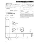
[0035]Referring now in detail to the drawings, FIG. 1 shows a system for repelling small mammals, for example voles, to prevent them from entering areas used for agriculture or horticulture, and provided, in general, with the reference symbol 1. This system 1 consists of individual segments 2, which are connected with one another to form a fence-like structure. This fence-like structure, consisting of segments 2, encloses a horticultural area that is indicated by individual trees 3.
[0036]In the corner region 4, where segments 2 meet at a right angle, a corner part 5 is provided. Corner part 5 consists of a square base plate 11 and side parts 12 that abut one another at a right angle, as shown in FIG. 6.
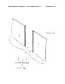
[0037]Individual segments 2 and also corner part 5 are attached to one another by means of a tongue/groove connection, for example, such as shown in FIGS. 7a and 7b, where tongue 14 of one side wall 7 fits with groove 15 of another side wall 7 to form the connection.
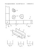
[0038]A segment 2 is shown in a perspective representation in FIG. 2. Segment 2 consists of a base plate 6 and two side walls 7 and 8, respectively, that rise from base plate 6 at a right angle.
[0039]An entry opening 9 is provided in side wall 7, which opening can be closed off by a flap 13, shown in FIG. 4. Flap 13 opens only in one direction so that the animal cannot exit out through the flap. The segment can also be structured without such a flap.
[0040]Base plate 6 is assembled to side plates 7 and 8 by way of insertion connections. In FIG. 2, the state that is also shown in FIG. 3a is shown. In this connection, tabs 16 (shown in FIG. 5) provided at the side edges of base plate 6 are inserted into a row of corresponding accommodation openings 10 in side plates 7.
[0041]As is evident from FIG. 2, multiple such rows of accommodation openings 10 are provided, at a distance from one another. In this connection, it is important that the uppermost row is so far away from the top edge that these accommodation openings 10 cannot serve as climbing aids for the animals trapped in the segment 2.
[0042]When assembling the segments 2, which consist of plastic plates, the possibility exists, as shown in FIG. 2 and in FIG. 3a, to merely set the segment down on the ground underneath, so that it is still possible to move and displace it afterwards.
[0043]In FIG. 3b, it is shown that side plates 7, 8 project downward beyond base plate 6, so that such a segment can be pressed into the ground to a slight extent.
[0044]Finally, in FIG. 3c it is shown that one of the side plates, either 7 or 8, can project further downward beyond base plate 6, while the opposite one remains in the state according to FIG. 3a. In this manner, a fence trap having such a structure is given an additional underground blocking effect.
[0045]Accordingly, while only a few embodiments of the present invention have been shown and described, it is obvious that many changes and modifications may be made thereunto without departing from the spirit and scope of the invention.
Claims:
1. A system for protecting areas used for agricultural or horticultural
purposes against small mammals, comprising:a plurality of segments
adapted to be assembled together to form a gutter that is open towards a
top, and forming a fence, each segment having a base plate and walls that
rise laterally from said base plate,wherein an inlet opening is provided
in at least one segment, in a side wall that faces away from the area to
be protected.
2. The system according to claim 1, further comprising a flap that closes off the inlet opening, said flap opening in only one direction.
3. The system according to claim 1, wherein each segment consists of plates that can be inserted into one another, wherein accommodation openings are provided in the side walls and receive insertion elements complementary to the accommodation openings, said insertion elements being provided in the side edges of the base plate, to assemble the plates together.
4. The system according to claim 3, wherein the accommodation openings are disposed in multiple rows, on top of one another.
5. The system according to claim 1, wherein the segments are composed of plastic plates inserted into one another.
6. The system according to claim 1, further comprising a segment having a square base plate and side walls that abut each other at a right angle, for the formation of corner regions.
7. The system according to claim 1, wherein the segments can be inserted into one another by way of tongue/groove connections.
Description:
CROSS REFERENCE TO RELATED APPLICATIONS
[0001]Applicants claim priority under 35 U.S.C. 119 of German Application No. 10 2007 057 244.3 filed Nov. 28, 2007.
BACKGROUND OF THE INVENTION
[0002]1. Field of the Invention
[0003]The invention relates to a system for repelling small mammals, for example voles, from areas used for agricultural or horticultural purposes.
[0004]2. The Prior Art
[0005]In order to protect such areas in agriculture or horticulture from voles or rats, for example, and to prevent these animals from penetrating into these areas, fences are put up, for example, which project into the ground to a depth of 30 to 40 cm, in order to make it difficult for the animals to get under them.
[0006]These fences, which are installed in a fixed manner and dug deeply into the ground, not only have the disadvantage of labor-intensive construction, but also the further disadvantage that if the cultivated area changes, they are not easily moved.
[0007]Furthermore, in addition to the attempt to deny the rodents access to the areas mentioned above, an attempt is furthermore made to keep the population density of the small mammals as low as possible. For this purpose, it has already been proposed to set up trough-like structures next to the areas to be protected, which have an access opening in a side wall, which might be provided with a flap that opens only in the access direction, but are configured to be open towards the top.
[0008]If an animal now enters this trough, it has no possibility of exiting this trough again, since the side walls are so high that it is impossible to cross them or climb up on them. The small mammals sitting in such traps can then be caught by predators such as raptors, foxes, or cats.
SUMMARY OF THE INVENTION
[0009]It is an object of the invention to combine both the blocking effect of a fence and the capturing effect of a trap with one another, using a single system.
[0010]The invention accomplishes this task with a system that consists of segments to be put together to form a gutter that is open towards the top, forming a type of fence, each having a base plate and walls that rise laterally from this base plate. An inlet opening is provided, at least in the side wall that faces away from the area to be protected.
[0011]The segments, which are connected with one another, one behind the other, thus form a barrier and, for another thing, also a trap, by means of the gutter-like structure.
[0012]Such a system can be easily moved by disassembly and reassembly, and this requires significantly less labor than erecting a fence.
[0013]The entry openings in the segments can be closed off, as described above, with a flap that opens only in the entry direction, so that the animals can enter the gutter, but not out again.
[0014]For humane reasons, however, it is desired, in many countries, for the animals to have a possibility to exit the gutter again, since they would starve if they have not already been captured by predators.
[0015]This humane aspect benefits from the experience that the animals generally find their way out again through the entry opening through which they entered. Experience has shown that the animals search for an exit opening on the wall that lies opposite the entry opening (in the direction of the area to be protected), and if they do not find an exit opening, they move along this wall, so that predators have the opportunity to catch the small mammal during this time, but the small mammal also has the opportunity to find one of the entry openings after a certain amount of time, after all, and to exit the gutter.
[0016]In a preferred embodiment of the invention, each segment consists of plates that can be inserted into one another, and accommodation openings are provided in the side walls, for insertion elements complementary to these accommodation openings, situated at the side edges of the base plate.
[0017]The production of such plates is significantly simpler, as are storage and transport, in contrast to the production of a gutter-shaped segment in one piece.
[0018]By simply putting together a base part and two side parts, a segment is created, and afterwards, this segment is lined up with others having a similar structure.
[0019]Preferably, the accommodation openings are disposed in multiple rows, on top of one another. In this way, a segment is created that can easily be displaced in the x-y direction.
[0020]By utilizing a row of accommodation openings disposed above this, the side walls reach beyond the base plate towards the bottom, so that these can be inserted into the ground.
[0021]Another possibility results in that, for example, the base plate is inserted into the lower row of accommodation openings of the side wall on the side that lies towards the area to be protected, while the base plate is inserted into a higher row of accommodation openings of the side wall on the opposite side. In this way, it is guaranteed that the side wall reaches farther into the ground on the entry opening side than on the opposite side. Thus, an underground blocking effect is also achieved.
[0022]It is advantageous if the segments are put together from plastic plates; this allows inexpensive production, for one thing, and for another brings with it the advantage that such segments do not rot quickly.
[0023]By putting them together skillfully, corner regions can also be produced using the three segment parts described above. However, in order to make the system complete, a square base plate having side walls that abut one another at a right angle, is provided, to form such corner regions, in each instance.
[0024]If the system is not supposed to completely enclose the region to be protected (if, for example, a masonry wall is already present), additional face elements for closing off the end of the gutter are provided.
[0025]Although various possibilities can be imagined for connecting the individual segments with one another, the gutter-shaped segments can be inserted into one another by way of tongue/groove connections. Such tongue/groove connections can be formed into the plastic plates during the production process.
BRIEF DESCRIPTION OF THE DRAWINGS
[0026]Other objects and features of the present invention will become apparent from the following detailed description considered in connection with the accompanying drawings. It is to be understood, however, that the drawings are designed as an illustration only and not as a definition of the limits of the invention.
[0027]In the drawings, wherein similar reference characters denote similar elements throughout the several views:
[0028]FIG. 1 shows a system according to one embodiment of the invention, disposed to form a fence, in a broken-off representation;
[0029]FIG. 2 shows an individual segment of the system;
[0030]FIGS. 3a to c show alternatives for inserting the segments into one another;
[0031]FIG. 4 shows a flap connected to one of the segments;
[0032]FIG. 5 shows the base plate of one of the segments;
[0033]FIG. 6 shows a corner segment; and
[0034]FIGS. 7a and 7b shows a the connection of two segments to one another.
DETAILED DESCRIPTION OF THE PREFERRED EMBODIMENT
[0035]Referring now in detail to the drawings, FIG. 1 shows a system for repelling small mammals, for example voles, to prevent them from entering areas used for agriculture or horticulture, and provided, in general, with the reference symbol 1. This system 1 consists of individual segments 2, which are connected with one another to form a fence-like structure. This fence-like structure, consisting of segments 2, encloses a horticultural area that is indicated by individual trees 3.
[0036]In the corner region 4, where segments 2 meet at a right angle, a corner part 5 is provided. Corner part 5 consists of a square base plate 11 and side parts 12 that abut one another at a right angle, as shown in FIG. 6.
[0037]Individual segments 2 and also corner part 5 are attached to one another by means of a tongue/groove connection, for example, such as shown in FIGS. 7a and 7b, where tongue 14 of one side wall 7 fits with groove 15 of another side wall 7 to form the connection.
[0038]A segment 2 is shown in a perspective representation in FIG. 2. Segment 2 consists of a base plate 6 and two side walls 7 and 8, respectively, that rise from base plate 6 at a right angle.
[0039]An entry opening 9 is provided in side wall 7, which opening can be closed off by a flap 13, shown in FIG. 4. Flap 13 opens only in one direction so that the animal cannot exit out through the flap. The segment can also be structured without such a flap.
[0040]Base plate 6 is assembled to side plates 7 and 8 by way of insertion connections. In FIG. 2, the state that is also shown in FIG. 3a is shown. In this connection, tabs 16 (shown in FIG. 5) provided at the side edges of base plate 6 are inserted into a row of corresponding accommodation openings 10 in side plates 7.
[0041]As is evident from FIG. 2, multiple such rows of accommodation openings 10 are provided, at a distance from one another. In this connection, it is important that the uppermost row is so far away from the top edge that these accommodation openings 10 cannot serve as climbing aids for the animals trapped in the segment 2.
[0042]When assembling the segments 2, which consist of plastic plates, the possibility exists, as shown in FIG. 2 and in FIG. 3a, to merely set the segment down on the ground underneath, so that it is still possible to move and displace it afterwards.
[0043]In FIG. 3b, it is shown that side plates 7, 8 project downward beyond base plate 6, so that such a segment can be pressed into the ground to a slight extent.
[0044]Finally, in FIG. 3c it is shown that one of the side plates, either 7 or 8, can project further downward beyond base plate 6, while the opposite one remains in the state according to FIG. 3a. In this manner, a fence trap having such a structure is given an additional underground blocking effect.
[0045]Accordingly, while only a few embodiments of the present invention have been shown and described, it is obvious that many changes and modifications may be made thereunto without departing from the spirit and scope of the invention.
User Contributions:
Comment about this patent or add new information about this topic:
Images included with this patent application:
 |  |
 |  |
| Similar patent applications: | |
| Date | Title |
|---|---|
| 2013-06-27 | Electrified bird repellent track |
| 2014-02-06 | Stem guides and replaceable cartridges |
| 2013-10-31 | Seat for spinning reel |
| 2014-02-27 | Method and apparatus for controlling burrowing animals |
| 2014-03-06 | Rubber or soft plastic fishing spoon lure |
| New patent applications in this class: | |
| Date | Title |
|---|---|
| 2016-06-09 | Mouse trap |
| 2016-05-19 | Quick setting trap with enhanced safety features |
| 2016-03-17 | Animal trap |
| 2016-03-03 | Cage trap with easy set and release mechanism |
| 2016-02-25 | Systems and methods for trapping animals |
| Top Inventors for class "Fishing, trapping, and vermin destroying" | |
| Rank | Inventor's name |
|---|---|
| 1 | Bruce Donoho |
| 2 | James H. Cink |
| 3 | Mike P. Tolley |
| 4 | Gary Bennis |
| 5 | Marko Konstantin Lubic |