Patent application title: ACTIVATION CONTROL DEVICE FOR THE CLUTCH PACKS OF A HYDRAULIC DOUBLE CLUTCH
Inventors:
Laurent Koopmann (Zedelgem, BE)
Assignees:
HOERBIGER ANTRIEBSTECHNIK GMBH
IPC8 Class: AF16H6126FI
USPC Class:
477130
Class name: By input manifold pressure or engine fuel control shift valve control plural shift valves
Publication date: 2009-05-21
Patent application number: 20090131219
ice for clutch packs of a hydraulic double clutch
is described and illustrated, and in some embodiments comprises a first
pressure line having a filling valve and leading from an oil pressure
source to the first clutch pack; a second pressure line having a filling
valve and leading from the oil pressure source to the second clutch pack;
and first and second draining valves coupled to the first and second
pressure lines, respectively, the first draining valve located between
the filling valve of the first pressure line and the first clutch pack,
and the second draining valve located between the filling valve of the
second pressure line and the second clutch pack.Claims:
1. An activation control device for clutch packs of a hydraulic double
clutch, the activation control device comprising:a first pressure line
having a filling valve and leading from an oil pressure source to the
first clutch pack;a second pressure line having a filling valve and
leading from the oil pressure source to the second clutch pack; andfirst
and second draining valves coupled to the first and second pressure
lines, respectively, the first draining valve located between the filling
valve of the first pressure line and the first clutch pack, and the
second draining valve located between the filling valve of the second
pressure line and the second clutch pack.
2. The activation control device of claim 1, wherein at least one of the filling valves is a proportional pressure reducing valve, and at least one of the draining valves is an on-off 3/2 valve.
3. The activation control device of claim 1, wherein each draining and filling valve has a respective spool, and wherein the diameters of the draining valve spools are larger than the diameters of the filling valve spools.
4. The activation control device of claim 2, wherein each draining and filling valve has a respective spool, and wherein the diameters of the draining valve spools are larger than the diameters of the filling valve spools.
5. The activation control device of claim 1, wherein each of the draining valves have a symmetric spool design.
6. The activation control device of claim 2, wherein each of the draining valves have a symmetric spool design.
7. The activation control device of claim 3, wherein each of the draining valves has a symmetric spool design.
8. The activation control device of claim 1, wherein each of the filling valves has an asymmetric spool design.
9. The activation control device of claim 2, wherein each of the filling valves has an asymmetric spool design.
10. The activation control device of claim 3, wherein each of the filling valves has an asymmetric spool design.
11. The activation control device of claim 5, wherein each of the filling valves has an asymmetric spool design.
12. The activation control device of claim 1, wherein the first and the second pressure lines are disposed in parallel, and branch from a common pressure line to the oil pressure source.
13. The activation control device of claim 2, wherein the first and the second pressure lines are disposed in parallel, and branch from a common pressure line to the oil pressure source.
14. The activation control device of claim 3, wherein the first and the second pressure lines are disposed in parallel, and branch from a common pressure line to the oil pressure source.
15. The activation control device of claim 5, wherein the first and the second pressure lines are disposed in parallel, and branch from a common pressure line to the oil pressure source.
16. The activation control device of claim 8, wherein the first and the second pressure lines are disposed in parallel, and branch from a common pressure line to the oil pressure source.Description:
CROSS-REFERENCE TO RELATED APPLICATIONS
[0001]This is a continuation of PCT/EP2006/003825 filed on Apr. 25, 2006, and claims priority to European patent application no. 05009008.3 filed on Apr. 25, 2005. The entire contents of both earlier-filed applications are incorporated herein by reference.
FIELD OF THE INVENTION
[0002]The present invention relates to activation control devices for clutch packs of hydraulic double clutches.
BACKGROUND
[0003]Hydraulic double clutches are used for double clutch transmissions, and comprise first and second pressure lines leading from an oil pressure source via respective filling valves in each pressure line to first and the second clutch packs, respectively.
SUMMARY
[0004]It is an object underlying the present invention to provide an activation control device having improved and/or safer operating characteristics.
[0005]The activation control device according to an embodiment of the present invention comprises a draining valve in each of the pressures lines between the filling valve and the clutch pack. This provides the advantage of minimizing pressure drop upon draining, and provides a redundant control option in case of valve failure. Therefore, as both pressure lines comprise one valve primarily intended for supplying oil to the clutch packs and thus controlling the clutch pressure, and another valve for the purpose of shortening the reaction time of the entire activation control device, torque transmission can be optimized.
[0006]In some embodiments, the filling valve is a proportional pressure reducing valve. Also in some embodiments, the draining valve is preferably an on-off 3/2 valve.
[0007]In some embodiments, the diameter of the spool of the draining valve is bigger than the diameter of the spool of the filling valve.
[0008]Furthermore, in some embodiments the draining valves have a symmetric spool design, whereas the filling valves have an asymmetric spool design. However, in other embodiments, both valve types have the same spool design.
[0009]Further features and advantages of the present invention will become apparent from the following description of the single figure of the drawings.
BRIEF DESCRIPTION OF THE DRAWING
[0010]The accompanying drawing is a schematic view of an activation control device for clutch packs of a hydraulic double clutch.
DETAILED DESCRIPTION
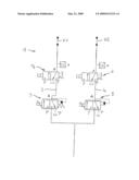
[0011]The accompanying drawing is a schematically simplified depiction of an activation control device 1 for clutch packs (represented by arrows K1 and K2) of a hydraulic double clutch used with a double clutch transmission (not shown).
[0012]The activation control device 1 comprises a first pressure line 2 equipped with a filling valve 3, and a draining valve 7 downstream of the filling valve 3. Therefore, the draining valve 7 is disposed between the filling valve 3 and the clutch pack K1.
[0013]Furthermore, a second pressure line 4 in parallel is provided with a filling valve 5 and a draining valve 6 downstream of filling valve 5, so that the draining valve 6 is disposed between filling valve 5 and the clutch pack K2.
[0014]The pressure lines 2 and 4 are connected to an oil pressure source not shown in the figure.
[0015]The connections of the valve terminals P, T, A to the pressure lines 2 and 4 can be understood with reference to the accompanying figure.
Claims:
1. An activation control device for clutch packs of a hydraulic double
clutch, the activation control device comprising:a first pressure line
having a filling valve and leading from an oil pressure source to the
first clutch pack;a second pressure line having a filling valve and
leading from the oil pressure source to the second clutch pack; andfirst
and second draining valves coupled to the first and second pressure
lines, respectively, the first draining valve located between the filling
valve of the first pressure line and the first clutch pack, and the
second draining valve located between the filling valve of the second
pressure line and the second clutch pack.
2. The activation control device of claim 1, wherein at least one of the filling valves is a proportional pressure reducing valve, and at least one of the draining valves is an on-off 3/2 valve.
3. The activation control device of claim 1, wherein each draining and filling valve has a respective spool, and wherein the diameters of the draining valve spools are larger than the diameters of the filling valve spools.
4. The activation control device of claim 2, wherein each draining and filling valve has a respective spool, and wherein the diameters of the draining valve spools are larger than the diameters of the filling valve spools.
5. The activation control device of claim 1, wherein each of the draining valves have a symmetric spool design.
6. The activation control device of claim 2, wherein each of the draining valves have a symmetric spool design.
7. The activation control device of claim 3, wherein each of the draining valves has a symmetric spool design.
8. The activation control device of claim 1, wherein each of the filling valves has an asymmetric spool design.
9. The activation control device of claim 2, wherein each of the filling valves has an asymmetric spool design.
10. The activation control device of claim 3, wherein each of the filling valves has an asymmetric spool design.
11. The activation control device of claim 5, wherein each of the filling valves has an asymmetric spool design.
12. The activation control device of claim 1, wherein the first and the second pressure lines are disposed in parallel, and branch from a common pressure line to the oil pressure source.
13. The activation control device of claim 2, wherein the first and the second pressure lines are disposed in parallel, and branch from a common pressure line to the oil pressure source.
14. The activation control device of claim 3, wherein the first and the second pressure lines are disposed in parallel, and branch from a common pressure line to the oil pressure source.
15. The activation control device of claim 5, wherein the first and the second pressure lines are disposed in parallel, and branch from a common pressure line to the oil pressure source.
16. The activation control device of claim 8, wherein the first and the second pressure lines are disposed in parallel, and branch from a common pressure line to the oil pressure source.
Description:
CROSS-REFERENCE TO RELATED APPLICATIONS
[0001]This is a continuation of PCT/EP2006/003825 filed on Apr. 25, 2006, and claims priority to European patent application no. 05009008.3 filed on Apr. 25, 2005. The entire contents of both earlier-filed applications are incorporated herein by reference.
FIELD OF THE INVENTION
[0002]The present invention relates to activation control devices for clutch packs of hydraulic double clutches.
BACKGROUND
[0003]Hydraulic double clutches are used for double clutch transmissions, and comprise first and second pressure lines leading from an oil pressure source via respective filling valves in each pressure line to first and the second clutch packs, respectively.
SUMMARY
[0004]It is an object underlying the present invention to provide an activation control device having improved and/or safer operating characteristics.
[0005]The activation control device according to an embodiment of the present invention comprises a draining valve in each of the pressures lines between the filling valve and the clutch pack. This provides the advantage of minimizing pressure drop upon draining, and provides a redundant control option in case of valve failure. Therefore, as both pressure lines comprise one valve primarily intended for supplying oil to the clutch packs and thus controlling the clutch pressure, and another valve for the purpose of shortening the reaction time of the entire activation control device, torque transmission can be optimized.
[0006]In some embodiments, the filling valve is a proportional pressure reducing valve. Also in some embodiments, the draining valve is preferably an on-off 3/2 valve.
[0007]In some embodiments, the diameter of the spool of the draining valve is bigger than the diameter of the spool of the filling valve.
[0008]Furthermore, in some embodiments the draining valves have a symmetric spool design, whereas the filling valves have an asymmetric spool design. However, in other embodiments, both valve types have the same spool design.
[0009]Further features and advantages of the present invention will become apparent from the following description of the single figure of the drawings.
BRIEF DESCRIPTION OF THE DRAWING
[0010]The accompanying drawing is a schematic view of an activation control device for clutch packs of a hydraulic double clutch.
DETAILED DESCRIPTION
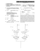
[0011]The accompanying drawing is a schematically simplified depiction of an activation control device 1 for clutch packs (represented by arrows K1 and K2) of a hydraulic double clutch used with a double clutch transmission (not shown).
[0012]The activation control device 1 comprises a first pressure line 2 equipped with a filling valve 3, and a draining valve 7 downstream of the filling valve 3. Therefore, the draining valve 7 is disposed between the filling valve 3 and the clutch pack K1.
[0013]Furthermore, a second pressure line 4 in parallel is provided with a filling valve 5 and a draining valve 6 downstream of filling valve 5, so that the draining valve 6 is disposed between filling valve 5 and the clutch pack K2.
[0014]The pressure lines 2 and 4 are connected to an oil pressure source not shown in the figure.
[0015]The connections of the valve terminals P, T, A to the pressure lines 2 and 4 can be understood with reference to the accompanying figure.
User Contributions:
Comment about this patent or add new information about this topic:
Images included with this patent application:
 |  |
| New patent applications in this class: | |
| Date | Title |
|---|---|
| 2011-03-31 | Hydraulic control systems for dual clutch transmissions |
| 2010-08-12 | Hydraulic control device of automatic transmission |
| 2010-06-10 | Transmission apparatus and vehicle having the same |
| 2010-04-22 | Control system for dual clutch transmission |
| 2010-04-01 | Hydraulic control apparatus for automatic transmission |
| Top Inventors for class "Interrelated power delivery controls, including engine control" | |
| Rank | Inventor's name |
|---|---|
| 1 | Alex O'Connor Gibson |
| 2 | Jeffrey Allen Doering |
| 3 | Atsushi Tabata |
| 4 | Seung-Hoon Lee |
| 5 | Anthony H. Heap |