Patent application title: Apparatus For Protecting A Pacemaker
Inventors:
Frank Armstrong (Waldwick, NJ, US)
Sharon M. Spinnler (Waldwick, NJ, US)
IPC8 Class: AA41D13015FI
USPC Class:
2455
Class name: Apparel guard or protector
Publication date: 2009-05-21
Patent application number: 20090126087
ates to protective apparatus suitable to provide
users of electrical implantable medical devices protection from impacts.
More specifically, the present invention relates to protective apparatus
suitable to provide users of pacemakers, both internal and external,
protection from impacts due to applied or external forces. The apparatus
comprises a rigid or semi-rigid outer shell or layer, an impact absorbing
inner pad or layer and, optionally, a recess for containing an external
electronic device. The outer shell or layer provides impact and
deformation resistance while distributing impact forces. The outer shell
or layer is formed using a sufficiently thermally pliable material
capable of molding to the body part containing, or in contact with, the
electronic device. Electrical implantable medical devices are further
protected by the inner pad or layer comprising a high density closed cell
foam. External electrical implantable medical device may be further
protected in an optional recess comprising low density open cell foam.Claims:
1. An apparatus for protecting a medical implantable device comprising:an
outer shell comprising a rigid material, the outer shell having a hollow
shape, an inside diameter, a front side and a back side, wherein the
rigid material is thermally pliable and capable of being molded to a body
part containing the medical implantable device; andan inner pad attached
to the outer shell, the inner pad comprising an impact absorbing
material.
2. The apparatus of claim 1, wherein the rigid material is at least one of plastics, thermoplastics, reinforced plastics, metals, metal alloys, and composites.
3. The apparatus of claim 1, wherein the impact absorbing material is at least one of rubber and high density closed cell foam.
4. The apparatus of claim 1, wherein the inner pad further comprises a recess on the back side of the inner pad capable of covering an internal or an external pacemaker, the recess having a front side and a back side.
5. The apparatus of claim 1, wherein the recess further comprises a rubber or low density open cell foam.
6. An apparatus for protecting a medical implantable device comprising:an outer layer comprising a rigid material, the outer layer having a front side, and a back side, and wherein the rigid material is thermally pliable and capable of molding to a body part in contact with the medical implantable device;an inner layer comprising an impact absorbing material, the inner layer having a front side and a back side and wherein the front side of the inner layer is attached to the back side of the outer layer; anda garment comprising a compartment capable of housing a medical implantable protecting means, wherein the compartment is located substantially over the body part containing the medical implantable device.
7. The apparatus of claim 6, wherein the rigid material has a thickness measured between the outer layer front side and outer layer back side between 1/16 inch and 1/4 inch.
8. The apparatus of claim 6, wherein the impact absorbing material has a thickness measured between the inner layer front side and inner layer back side between 1/8 inch and 3/4 inch.
9. The apparatus of claim 6, wherein the inner layer further comprises a recess on the back side of the inner layer capable of covering the implantable medical device.
10. The apparatus of claim 6, wherein the recess further comprises a rubber or low density open cell foam.
11. A system to protect an implantable medical device, the system comprising:an outer shell comprising a rigid material, the outer shell having a hollow shape, an inside diameter, a front side and a back side, wherein the rigid material is thermally pliable and capable of being molded to a body part containing the implantable medical device;an inner pad attached to the outer shell, the inner pad comprising an impact absorbing material; anda garment, wherein the garment comprises a sealable compartment capable of housing the implantable medical device.
12. The system of claim 11, wherein the compartment is located over a body part containing the implantable medical device.Description:
CROSS REFERENCE TO RELATED APPLICATIONS
[0001]The present application claims the benefit of U.S. Provisional Application Ser. No. 61/000,788, filed Oct. 29, 2007, the disclose of which is expressly incorporated herein by reference in its entirety.
FIELD OF THE INVENTION
[0002]The present invention relates to protective apparatus suitable to provide users of electrical implantable medical devices protection from impacts. More specifically, the present invention relates to protective apparatus suitable to provide users of pacemakers, both internal and external, protection from impacts due to applied or external forces.
BACKGROUND OF THE INVENTION
[0003]Protective apparatus is used to protect objects from experiencing an impact from applied and/or external forces. Electrical implantable medical devices, such as cardiac pacemakers, defibrillators, and active drug pumps, are susceptible to damage from impacts. Since the effects of a damaged or non-functioning medical device on a user can be catastrophic, such impacts should be minimized or avoided.
[0004]For instance, when involved in a physical, recreational, or sporting activity, a user of an internal pacemaker may receive an impact to the skin over the device. An impact to the chest or abdomen near the pacemaker could fracture the pacing wire(s) and affect its functioning. To reduce the risk of internal pacemaker fracture and/or harm to the pacemaker user, a protective apparatus may be employed.
[0005]Many existing protective devices or paddings do not adequately protect objects from damaging impacts. With respect to implantable medical devices, U.S. Patent Publication No. 2005/0256621 by Lange describes a device for protecting a contact sensitive or injured point of the human body or a pacemaker user. Lange's device, however, is designed to protect users against abrasions and rubbing from safety belts and, as a result, the device is characterized by a surface uninterrupted by protrusions or edges rather than designed to resist impacts. Lange's device is not suitable for, nor directed at, protecting electrical implantable medical devices or users from impacts.
[0006]To be effective, protective apparatus must be in place over the protected object and, preferable, contoured to or domed over the part of the body containing, or in contact with, the device being protected. Protective apparatus are typically applied during rest prior to activity. During activity, uncontoured or non-domed apparatus can shift due to either improper fit, user discomfort and adjustment, or simple movement. A displaced protective apparatus does not provide optimal protection for objects from damage or otherwise experiencing an impact from forces being applied to them.
[0007]As such, there is a need for protective apparatus suitable to provide users of implantable medical devices sufficient protection from impacts via applied or external forces and, optionally, capable of being shaped to fit a contoured body part to prevent displacement.
SUMMARY OF THE INVENTION
[0008]The present invention is directed to an apparatus for protecting a pacemaker comprising (a) an outer shell comprising a rigid material, the outer shell having a hollow shape, an inside diameter, a front side, and a back side, and wherein the rigid material is thermally pliable and capable of molding to a body part containing, or in contact with, the pacemaker, and (b) an inner pad attached to the outer shell, the inner pad comprising an impact absorbing material, the inner pad having an outside diameter, a front side, and a back side.
[0009]The present invention is also directed to an apparatus for protecting a pacemaker comprising (a) an outer layer comprising a rigid material, the outer layer having a front side, and a back side and wherein the rigid material is thermally pliable and capable of molding to a body part containing or in contact with the pacemaker, and (b) an inner layer comprising an impact absorbing material, the inner layer having a front side and a back side and wherein the front side of the inner layer is attached to the back side of the outer layer.
BRIEF DESCRIPTION OF THE DRAWINGS
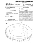
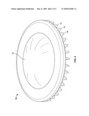
[0010]FIGS. 1 and 2 show embodiments of the present invention apparatus wherein the outer shell has raised ridges and wherein the inner pad is contained within the outer shell.
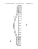
[0011]FIG. 3 shows another embodiment of the present invention apparatus wherein the outside diameter of the inner pad is connected to, and embedded in, the outside shell.
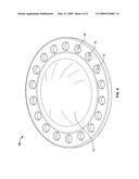
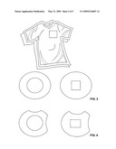
[0012]FIG. 4 shows another embodiment of the present invention apparatus wherein the outer shell possesses holes protruding from the front side to the back side and formed in a ring around the outer shell.
[0013]FIGS. 5 and 6 show another embodiment of the present invention wherein the protective apparatus is contained in a garment comprising a compartment for housing the apparatus.
DETAILED DESCRIPTION OF THE INVENTION
[0014]The present invention relates to protective apparatus suitable to provide users of electrical implantable medical devices protection from impacts. More specifically, the present invention relates to protective apparatus suitable to provide users of pacemakers, both internal and external, protection from impacts due to applied or external forces.
[0015]As used herein the term "electrical implantable medical device" refers to electronic devices having a medical purpose which are completely or partially implanted within the human body. Examples of such devices include, but are not limited to, cardiac pacemakers, defibrillators, and active drug pumps.
[0016]As used herein the term "thermally pliable" refers to a material that, upon reaching a minimal temperature, is supple or adjustable enough to bend freely without breaking. The term includes materials that may by supple or adjustable during formation, such as ABS plastic formed by injection molding processes or similar processes known in the art. Injection molding processes include pour molding, injection molding, compression molding, or other known techniques. The term also includes materials that may be inherently supple and adjustable after formation, and materials that may be supple and adjustable after formation by the application of thermal heat, such as ORTHOPLAST®.
[0017]As used herein the term "capable of molding to a body part" refers to a material that can be molded to fit over a body part. The term includes materials that can be molded to partially or substantially match the contours of the body part containing, or in contact with, the implantable medical electrical device to be protected. The molding may occur at formation using injection molding processes or similar processes known in the art. The molding may also occur after formation, such as by the application of thermal heat.
[0018]As used herein the term "high density" refers to a density greater than about 1.0 pounds per cubic foot (lb/cu.ft).
[0019]As used herein the term "closed cell foam" refers to a foam having at least 50% of the cell present intact.
[0020]As used herein the term "low density" refers to a density less than about 1.0 pounds per cubic foot (lb/cu.ft).
[0021]As used herein the term "open cell foam" refers to a foam having at least 50% of the cells broken or missing a membrane.
[0022]The present invention is directed to an apparatus for protecting a pacemaker comprising (a) an outer shell comprising a rigid material, the outer shell having a hollow shape, an inside diameter, a front side and a back side, and wherein the rigid material is thermally pliable and capable of molding to a body part containing, or in contact with, the pacemaker, and (b) an inner pad attached to the outer shell, the inner pad comprising an impact absorbing material, the inner pad having a flat shape, an outside diameter, a front side and a back side.
[0023]In another embodiment, the present invention is directed to an apparatus for protecting a pacemaker comprising (a) an outer layer comprising a rigid material, the outer layer having a front side and a back side and wherein the rigid material is thermally pliable and capable of molding to a body part containing or in contact with the pacemaker, and (b) an inner layer comprising an impact absorbing material, the inner layer having a front side and a back side and wherein the front side of the inner layer is attached to the back side of the outer layer.
[0024]The material used to form the outer shell or layer may be selected from any rigid material known to one skilled in the medical, sports, or industrial protective covering industry, The selection of a rigid material may vary with the device or body part to be protected. Preferably, the material may comprise plastics, thermoplastics, reinforced plastics or thermoplastics comprising glass fibers, carbon fibers or both, metals, metal alloys, or composites. For example, protection from impacts such as falling to the ground may require a soft, but rigid, thermoplastic material. In contrast, protection from the impact of a bullet or an industrial accident may require a more rigid plastic, metal based material, or density fiberous material. Any rigid material known in the medical, sports and industrial protective covering industries.
[0025]The rigid material that comprises part of the invention may be thermally pliable at temperatures at or below the temperature typical of an industrial heat gun (e.g. 250° C.). The rigid material may also be thermally pliable at temperatures at or below the temperature typical of an industrial hair blow dryer (e.g. 100° C.). Further, the rigid material may be thermally pliable at temperatures at or below the temperature typical of a human body (e.g. 36° C. to 38° C.). Still further, the rigid material may be thermally pliable at or below temperatures above typical room temperature (e.g. 22° C. to 28° C.).
[0026]In a preferred embodiment, the rigid material may be fabricated from ABS plastic or ABS polycarbonite plastic. ABS is an easily machined, tough, low cost rigid thermoplastic material with high impact strength. ABS plastic has good stress cracking resistance to physical forces, as well as, excellent abrasion resistance, electrical properties and moisture resistance.
[0027]In another preferred embodiment, the rigid material may be fabricated from plastic, thermoplastic, low-temperature thermoplastic, or low-temperature thermoplastic comprising substantial malleability at about 180° F. Most preferably, the material is fabricated from ORTHOPLAST® thermoplastic, manufactured by Johnson and Johnson.
[0028]Upon reading this specification, those with ordinary skill in the art will understand that, under appropriate circumstances, such as available materials, user preference, advances in technology, etc., other low temperature thermally formable materials, such as MULTIFORM PLASTIC®, X-LITE PLUS®, EZEFORM SPLINTING MATERIAL®, MULTIFORM CLEAR®, etc., may suffice.
[0029]The thermally pliable rigid material may be conformed to or domed over the contoured object or body part to be protected. In one embodiment, the outer shell or layer may be anatomically conformable to the shape of the component, device or body part, such that the protective apparatus adapts to the user's specific physiology. In another embodiment, the outer shell or layer may be in the form of a doom.
[0030]The thermally pliable rigid material can be selected to remain pliable at or near ambient body temperature. By using this material, an outer shell or layer retains the ability to adjust its shape to the resulting shape changes that occur when the contour of the component, device or body, changes through motion.
[0031]In a preferred embodiment, the protective apparatus of the present invention is useful for remaining in place during activity or while a user is moving. The contoured or domed shape preferably fits best over the contoured part it is designed to cover. Any movement of the protective covering from the best fit, is preferably corrected by the subsequent movements back to the best fit. The contoured or domed shape is preferably self-correcting when moved from the best fit position.
[0032]The apparatus of the present invention may be used to protect electrical implantable medical devices that are contained, in or connected to, all parts of the human body, such as the chest, torso, abdomen, groin, head, neck, shoulders, arms, wrist, hands, legs, back, buttocks, knees, ankles and feet.
[0033]The outer shell or layer may have a sufficient thickness to provide structurally integrity to the apparatus and still remain comfortable to the user when the apparatus is worn under and in conjunction with clothing. The thickness of the outer shell, preferably, should not hinder the user from performing common physically activities. The thickness of the protective outer shell may depend on many factors, including the type of impact or projectile anticipated to be encountered, the speed and resulting force of the impact and the level of protection sought. Other considerations such as density of the material and shock absorption properties may also be factors in selecting an appropriate material and thickness. These factors that are disclosed herein are provided for illustrative purposes and are in no way disclosed to limit the factors in selecting an appropriate material or thickness for the protective outer shell or layer.
[0034]In a preferred embodiment, the thickness of the outer shell or layer measured between the respective front and back sides is between 1/32 inch and 1/2 inch. More preferably, the thickness of the outer shell or layer measured between the respective front and back sides is between 1/16 inch and 1/4 inch.
[0035]In an exemplary embodiment, the rigid material is ABS plastic having a thickness of about 1/8 inch.
[0036]The outer shell or layer of the present invention is useful for providing improved impact and deformation resistance by dispersing the impact force. The outer shell or layer disperse the impact energy from a source over the entire shell or layer, and optionally, over the inner pad or layer materials. The contoured or domed shape of the outer shell or layer disperses the impact evenly over the body part containing, or in contact with, the electrical implantable medical device. By evenly dispersing the impact, the body part or device being protected experiences a reduced impact force.
[0037]Various shapes of the apparatus (outer shell or layer and/or inner pad or layer) for protecting an electronic implantable medical device are contemplated. For example, such shapes may include a circle, an ellipse, a square, a rectangle, a circle with one or more cutouts, or any other suitable shape. In one embodiment, the outer shell has a circular shape in the form of a doom. In another embodiment, the outer shell has a circular shape in the form of a flat, hollow disc. The choice of shape for both the outer shell and layer may be dependent on, and varied, with the type of device and/or body part to be protected. For example, a square-like shape may be best suited to protect a square-like implantable medical device, whereas a disc-like shape may be best suited to protect a disc-like implantable medical device.
[0038]The inner pad or layer is preferably formed from an impact absorbing material. The material used to form the inner pad or layer may be selected from any rubber or high density closed cell foam known to one skilled in the art of the rubber, insulation, cushioning or packaging industry. The selection of rubber or high density closed cell foam may vary with the device or body part to be F protected.
[0039]The rubber material used as an impact absorbing material may comprise natural rubber, isoprene rubber, butadiene rubber, butyl rubber, silicone rubber, fluorine rubber, polystyrene rubber, nitrile rubber, polystyrene butadiene rubber, chloroprene rubber, urethane rubber, polystyrene ethylene) rubber, an ethylenepropylenediene methylene copolymer, polyacetal, polyurethane rubber, foam rubber or combinations thereof.
[0040]The rubber material used as the impact absorbing material may have a durometer value ranging from ShoreAll through D90. Preferably, the rubber material used as an impact absorbing material may have a Shore A durometer of between 10 and 100. More preferably, the rubber material may have a Shore A durometer of between 10 and 70.
[0041]Preferably, the rubber material used as an impact absorbing material may have a Shore D durometer of between 10 and 100. More preferably, the rubber material may have a Shore D durometer of between 65 and 94.
[0042]In exemplary embodiments, the rubber material is ShoreAll, ShoreA60 or ShoreD90.
[0043]The high density closed cell foam may comprise polyimides (annealed or heat treated), polyurethanes, polystyrene, polyolefins, polyvinyl chloride, cellular cellulose acetate or combinations thereof.
[0044]Selection of a rubber or high density closed cell foam may, preferably, have a sufficient density such that the inner pad or layer can absorb the energy of high velocity impacts. For example, if a projectile for which protection is sought is a from a high school male baseball player, the appropriate foam selected should be able to absorb high energies such as those accompanying a baseball being thrown at 90 miles per hour (MPH). Preferably, the thickness of the inner pad or layer measured between the respective front and back sides is between 1/32 inch and 1 inch. More preferably, the thickness of the outer shell or layer measured between the respective front and back sides is between 1/8 inch and 3/4 inch.
[0045]In an exemplary embodiment, a rubber or high density closed cell foam having a thickness of 1/2 inch may be used. Of course, those skilled in the art will appreciate that other thicknesses may be used depending on the characteristics of the rubber or high density impact absorbing foam used.
[0046]The outer shell or layer and inner pad or layer, respectively, are attached to each other. The attachment may be physical such as tying, wrapping, encasing or anchoring with a string, rope, fabric or tape. The connection may be chemical such as bonding, gluing, or melting a thermoplastic resin, glue, or adhesive. Any physical or chemical connection means or material known in the medical, sports and industrial protective covering industry may be used.
[0047]FIGS. 1-4 show embodiments of the protective apparatus contemplated in the present invention. FIGS. 1 and 2 show the front side and back side views of both an outer shell and an inner pad. The outer shell (10) is shown as a disc-like shape which encircles an inner pad (12). The outer shell (10) has raised ridges (14) to help cushion the impact from an applied or external force. FIGS. 1 and 2 show that the external diameter area of the inner pad is attached to the inner diameter area of the outer shell. FIG. 4 shows an alternate outer shell design. The outer shell (10) surrounding the inner pad (12) has a disc-like shape with circular cut outs (16) to help cushion the impact from an applied or external force.
[0048]The attachment between the outer shell and inner pad may also be overlapped, overmolded and/or entwined. In FIG. 3, the outside diameter of the inner pad (12) is connected to, and embedded in, the outside shell (10). The outside shell partially wraps around the inner disc to provide additional protection to the inner disc and an improved attachment between the outer shell (10) and inner disc (12).
[0049]The protective apparatus of the present invention may also comprise a recess in or attached to the inner pad or layer. This recess is preferable located in substantially the center of the inner pad or layer. The location may be varied depending on the nature and shape of the device or body part to be protected. External electrical implantable devices, such as external pacemakers, may be placed inside the recess to be protected from impacts.
[0050]The optional recess has a thickness or depth measured between the recess front side and back side between 1/16 inch and 1/2 inch. The thickness or depth is dependant on the thickness of the inner pad or layer. Preferably, the thickness or depth of the recess measured between the recess front side and back side is between 1/8 inch and 1/4 inch.
[0051]The recess may be filled with a rubber, low density open cell foam or suitable replacement to surround and provide additional protection to a pacemaker. The material used to form the rubber or low density open cell foam may be any material known to one skilled in the art of the rubber, insulation, cushioning or packaging industry. The selection of rubber or low density open cell foam may vary with the device or body part to be protected.
[0052]The rubber material used as an impact absorbing material in the recess may comprise natural rubber, isoprene rubber, butadiene rubber, butyl rubber, silicone rubber, fluorine rubber, polystyrene rubber, nitrile rubber, polystyrene butadiene rubber, chloroprene rubber, urethane rubber, polystyrene ethylene) rubber, an ethylenepropylenediene methylene copolymer, polyacetal, polyurethane rubber, foam rubber or combinations thereof.
[0053]The rubber material used as the impact absorbing material may have a durometer value ranging from ShoreAll through D90. Preferably, the rubber material used as an impact absorbing material in the recess may have a Shore A durometer of between 10 and 100. More preferably, the rubber material may have a Shore A durometer of between 10 and 70.
[0054]Preferably, the rubber material used as an impact absorbing material in the recess may have a Shore D durometer of between 10 and 100. More preferably, the rubber material has a Shore D durometer of between 65 and 94.
[0055]In exemplary embodiments, the rubber material is ShoreAll, ShoreA60 or ShoreD90.
[0056]The low density closed cell foam may comprise polyimides (annealed or heat treated), polyurethanes, polystyrene, polyolefins, polyvinyl chloride, cellular cellulose acetate or combinations thereof.
[0057]The invention may also include a system to protect an implantable electronic medical device comprising a garment and a protective device. The garment will house and secure the protective device in the proper location for protection. For example, a garment may have a pocket or pouch that may be stitched to the inside of the garment. This pocket may extend from the about the left shoulder seam to approximately 8 inches below with an opening of approximately 41/2 inches to allow placement of the guard. It should be noted that the dimensions disclosed herein are merely for illustrative purposed to explain the present invention and are in no way provided to limit the scope of the present invention. Within the pocket there may be a fastening system that attaches to the protective device in order to ensure proper placement of the protective device.
[0058]The garment and the protective device maybe fixedly attached and/or removably attached by a suitable fastener means of choice. In one embodiment, the garment and the protective device may include VELCRO® strips that are attached to each and allow for variable adjustment thereof. In another preferred embodiment, the use of tape, fasteners, clamps and the like can be employed to removably attached the protective device.
[0059]FIGS. 5 and 6 show embodiments of the present invention wherein the protective apparatus is contained in a garment containing a compartment for housing the apparatus.
[0060]Any apparel, athletic gear, or protective clothing known in the sports and industrial protective covering industry may be used. Examples of materials that may be used in the garment include, but are not limited to, nylon, polyester, acrylic, cotton, spandex, silk, LYCPA® spandex, ELASTANE® spandex, or similar fabrics.
[0061]The entire apparatus, entire or partial outer shell or layer, or entire inner pad or layer, may be partially or fully enclosed in a skin or fabric adjacent to the outer surfaces of the apparatus. The materials which may be used to form the skin or fabric may include LYCRA® spandex, cotton, polyester, rubber and other similar type materials. Considerations in selecting a material would include cost, protection, durability, flexibility, comfort, style and ease to work with in assembly. Of course, these factors would also apply to the choice of outer shell or layer and inner pad or layer materials.
[0062]While the protective device is intended and designed for impact resistance, those skilled in the art will appreciate that the device disclosed here may be adapted in numerous was, for example, an extremely slimmed down version of the protection device may be used by those who have pacemakers and find wearing a seatbelt over the device uncomfortable. The slimmed down device may be worn in the same manner described above or may be fitted with an attachment for a seatbelt that may be removable and that may slide along the belt for proper fitting and lock into place once the desired position is reached.
Claims:
1. An apparatus for protecting a medical implantable device comprising:an
outer shell comprising a rigid material, the outer shell having a hollow
shape, an inside diameter, a front side and a back side, wherein the
rigid material is thermally pliable and capable of being molded to a body
part containing the medical implantable device; andan inner pad attached
to the outer shell, the inner pad comprising an impact absorbing
material.
2. The apparatus of claim 1, wherein the rigid material is at least one of plastics, thermoplastics, reinforced plastics, metals, metal alloys, and composites.
3. The apparatus of claim 1, wherein the impact absorbing material is at least one of rubber and high density closed cell foam.
4. The apparatus of claim 1, wherein the inner pad further comprises a recess on the back side of the inner pad capable of covering an internal or an external pacemaker, the recess having a front side and a back side.
5. The apparatus of claim 1, wherein the recess further comprises a rubber or low density open cell foam.
6. An apparatus for protecting a medical implantable device comprising:an outer layer comprising a rigid material, the outer layer having a front side, and a back side, and wherein the rigid material is thermally pliable and capable of molding to a body part in contact with the medical implantable device;an inner layer comprising an impact absorbing material, the inner layer having a front side and a back side and wherein the front side of the inner layer is attached to the back side of the outer layer; anda garment comprising a compartment capable of housing a medical implantable protecting means, wherein the compartment is located substantially over the body part containing the medical implantable device.
7. The apparatus of claim 6, wherein the rigid material has a thickness measured between the outer layer front side and outer layer back side between 1/16 inch and 1/4 inch.
8. The apparatus of claim 6, wherein the impact absorbing material has a thickness measured between the inner layer front side and inner layer back side between 1/8 inch and 3/4 inch.
9. The apparatus of claim 6, wherein the inner layer further comprises a recess on the back side of the inner layer capable of covering the implantable medical device.
10. The apparatus of claim 6, wherein the recess further comprises a rubber or low density open cell foam.
11. A system to protect an implantable medical device, the system comprising:an outer shell comprising a rigid material, the outer shell having a hollow shape, an inside diameter, a front side and a back side, wherein the rigid material is thermally pliable and capable of being molded to a body part containing the implantable medical device;an inner pad attached to the outer shell, the inner pad comprising an impact absorbing material; anda garment, wherein the garment comprises a sealable compartment capable of housing the implantable medical device.
12. The system of claim 11, wherein the compartment is located over a body part containing the implantable medical device.
Description:
CROSS REFERENCE TO RELATED APPLICATIONS
[0001]The present application claims the benefit of U.S. Provisional Application Ser. No. 61/000,788, filed Oct. 29, 2007, the disclose of which is expressly incorporated herein by reference in its entirety.
FIELD OF THE INVENTION
[0002]The present invention relates to protective apparatus suitable to provide users of electrical implantable medical devices protection from impacts. More specifically, the present invention relates to protective apparatus suitable to provide users of pacemakers, both internal and external, protection from impacts due to applied or external forces.
BACKGROUND OF THE INVENTION
[0003]Protective apparatus is used to protect objects from experiencing an impact from applied and/or external forces. Electrical implantable medical devices, such as cardiac pacemakers, defibrillators, and active drug pumps, are susceptible to damage from impacts. Since the effects of a damaged or non-functioning medical device on a user can be catastrophic, such impacts should be minimized or avoided.
[0004]For instance, when involved in a physical, recreational, or sporting activity, a user of an internal pacemaker may receive an impact to the skin over the device. An impact to the chest or abdomen near the pacemaker could fracture the pacing wire(s) and affect its functioning. To reduce the risk of internal pacemaker fracture and/or harm to the pacemaker user, a protective apparatus may be employed.
[0005]Many existing protective devices or paddings do not adequately protect objects from damaging impacts. With respect to implantable medical devices, U.S. Patent Publication No. 2005/0256621 by Lange describes a device for protecting a contact sensitive or injured point of the human body or a pacemaker user. Lange's device, however, is designed to protect users against abrasions and rubbing from safety belts and, as a result, the device is characterized by a surface uninterrupted by protrusions or edges rather than designed to resist impacts. Lange's device is not suitable for, nor directed at, protecting electrical implantable medical devices or users from impacts.
[0006]To be effective, protective apparatus must be in place over the protected object and, preferable, contoured to or domed over the part of the body containing, or in contact with, the device being protected. Protective apparatus are typically applied during rest prior to activity. During activity, uncontoured or non-domed apparatus can shift due to either improper fit, user discomfort and adjustment, or simple movement. A displaced protective apparatus does not provide optimal protection for objects from damage or otherwise experiencing an impact from forces being applied to them.
[0007]As such, there is a need for protective apparatus suitable to provide users of implantable medical devices sufficient protection from impacts via applied or external forces and, optionally, capable of being shaped to fit a contoured body part to prevent displacement.
SUMMARY OF THE INVENTION
[0008]The present invention is directed to an apparatus for protecting a pacemaker comprising (a) an outer shell comprising a rigid material, the outer shell having a hollow shape, an inside diameter, a front side, and a back side, and wherein the rigid material is thermally pliable and capable of molding to a body part containing, or in contact with, the pacemaker, and (b) an inner pad attached to the outer shell, the inner pad comprising an impact absorbing material, the inner pad having an outside diameter, a front side, and a back side.
[0009]The present invention is also directed to an apparatus for protecting a pacemaker comprising (a) an outer layer comprising a rigid material, the outer layer having a front side, and a back side and wherein the rigid material is thermally pliable and capable of molding to a body part containing or in contact with the pacemaker, and (b) an inner layer comprising an impact absorbing material, the inner layer having a front side and a back side and wherein the front side of the inner layer is attached to the back side of the outer layer.
BRIEF DESCRIPTION OF THE DRAWINGS
[0010]FIGS. 1 and 2 show embodiments of the present invention apparatus wherein the outer shell has raised ridges and wherein the inner pad is contained within the outer shell.
[0011]FIG. 3 shows another embodiment of the present invention apparatus wherein the outside diameter of the inner pad is connected to, and embedded in, the outside shell.
[0012]FIG. 4 shows another embodiment of the present invention apparatus wherein the outer shell possesses holes protruding from the front side to the back side and formed in a ring around the outer shell.
[0013]FIGS. 5 and 6 show another embodiment of the present invention wherein the protective apparatus is contained in a garment comprising a compartment for housing the apparatus.
DETAILED DESCRIPTION OF THE INVENTION
[0014]The present invention relates to protective apparatus suitable to provide users of electrical implantable medical devices protection from impacts. More specifically, the present invention relates to protective apparatus suitable to provide users of pacemakers, both internal and external, protection from impacts due to applied or external forces.
[0015]As used herein the term "electrical implantable medical device" refers to electronic devices having a medical purpose which are completely or partially implanted within the human body. Examples of such devices include, but are not limited to, cardiac pacemakers, defibrillators, and active drug pumps.
[0016]As used herein the term "thermally pliable" refers to a material that, upon reaching a minimal temperature, is supple or adjustable enough to bend freely without breaking. The term includes materials that may by supple or adjustable during formation, such as ABS plastic formed by injection molding processes or similar processes known in the art. Injection molding processes include pour molding, injection molding, compression molding, or other known techniques. The term also includes materials that may be inherently supple and adjustable after formation, and materials that may be supple and adjustable after formation by the application of thermal heat, such as ORTHOPLAST®.
[0017]As used herein the term "capable of molding to a body part" refers to a material that can be molded to fit over a body part. The term includes materials that can be molded to partially or substantially match the contours of the body part containing, or in contact with, the implantable medical electrical device to be protected. The molding may occur at formation using injection molding processes or similar processes known in the art. The molding may also occur after formation, such as by the application of thermal heat.
[0018]As used herein the term "high density" refers to a density greater than about 1.0 pounds per cubic foot (lb/cu.ft).
[0019]As used herein the term "closed cell foam" refers to a foam having at least 50% of the cell present intact.
[0020]As used herein the term "low density" refers to a density less than about 1.0 pounds per cubic foot (lb/cu.ft).
[0021]As used herein the term "open cell foam" refers to a foam having at least 50% of the cells broken or missing a membrane.
[0022]The present invention is directed to an apparatus for protecting a pacemaker comprising (a) an outer shell comprising a rigid material, the outer shell having a hollow shape, an inside diameter, a front side and a back side, and wherein the rigid material is thermally pliable and capable of molding to a body part containing, or in contact with, the pacemaker, and (b) an inner pad attached to the outer shell, the inner pad comprising an impact absorbing material, the inner pad having a flat shape, an outside diameter, a front side and a back side.
[0023]In another embodiment, the present invention is directed to an apparatus for protecting a pacemaker comprising (a) an outer layer comprising a rigid material, the outer layer having a front side and a back side and wherein the rigid material is thermally pliable and capable of molding to a body part containing or in contact with the pacemaker, and (b) an inner layer comprising an impact absorbing material, the inner layer having a front side and a back side and wherein the front side of the inner layer is attached to the back side of the outer layer.
[0024]The material used to form the outer shell or layer may be selected from any rigid material known to one skilled in the medical, sports, or industrial protective covering industry, The selection of a rigid material may vary with the device or body part to be protected. Preferably, the material may comprise plastics, thermoplastics, reinforced plastics or thermoplastics comprising glass fibers, carbon fibers or both, metals, metal alloys, or composites. For example, protection from impacts such as falling to the ground may require a soft, but rigid, thermoplastic material. In contrast, protection from the impact of a bullet or an industrial accident may require a more rigid plastic, metal based material, or density fiberous material. Any rigid material known in the medical, sports and industrial protective covering industries.
[0025]The rigid material that comprises part of the invention may be thermally pliable at temperatures at or below the temperature typical of an industrial heat gun (e.g. 250° C.). The rigid material may also be thermally pliable at temperatures at or below the temperature typical of an industrial hair blow dryer (e.g. 100° C.). Further, the rigid material may be thermally pliable at temperatures at or below the temperature typical of a human body (e.g. 36° C. to 38° C.). Still further, the rigid material may be thermally pliable at or below temperatures above typical room temperature (e.g. 22° C. to 28° C.).
[0026]In a preferred embodiment, the rigid material may be fabricated from ABS plastic or ABS polycarbonite plastic. ABS is an easily machined, tough, low cost rigid thermoplastic material with high impact strength. ABS plastic has good stress cracking resistance to physical forces, as well as, excellent abrasion resistance, electrical properties and moisture resistance.
[0027]In another preferred embodiment, the rigid material may be fabricated from plastic, thermoplastic, low-temperature thermoplastic, or low-temperature thermoplastic comprising substantial malleability at about 180° F. Most preferably, the material is fabricated from ORTHOPLAST® thermoplastic, manufactured by Johnson and Johnson.
[0028]Upon reading this specification, those with ordinary skill in the art will understand that, under appropriate circumstances, such as available materials, user preference, advances in technology, etc., other low temperature thermally formable materials, such as MULTIFORM PLASTIC®, X-LITE PLUS®, EZEFORM SPLINTING MATERIAL®, MULTIFORM CLEAR®, etc., may suffice.
[0029]The thermally pliable rigid material may be conformed to or domed over the contoured object or body part to be protected. In one embodiment, the outer shell or layer may be anatomically conformable to the shape of the component, device or body part, such that the protective apparatus adapts to the user's specific physiology. In another embodiment, the outer shell or layer may be in the form of a doom.
[0030]The thermally pliable rigid material can be selected to remain pliable at or near ambient body temperature. By using this material, an outer shell or layer retains the ability to adjust its shape to the resulting shape changes that occur when the contour of the component, device or body, changes through motion.
[0031]In a preferred embodiment, the protective apparatus of the present invention is useful for remaining in place during activity or while a user is moving. The contoured or domed shape preferably fits best over the contoured part it is designed to cover. Any movement of the protective covering from the best fit, is preferably corrected by the subsequent movements back to the best fit. The contoured or domed shape is preferably self-correcting when moved from the best fit position.
[0032]The apparatus of the present invention may be used to protect electrical implantable medical devices that are contained, in or connected to, all parts of the human body, such as the chest, torso, abdomen, groin, head, neck, shoulders, arms, wrist, hands, legs, back, buttocks, knees, ankles and feet.
[0033]The outer shell or layer may have a sufficient thickness to provide structurally integrity to the apparatus and still remain comfortable to the user when the apparatus is worn under and in conjunction with clothing. The thickness of the outer shell, preferably, should not hinder the user from performing common physically activities. The thickness of the protective outer shell may depend on many factors, including the type of impact or projectile anticipated to be encountered, the speed and resulting force of the impact and the level of protection sought. Other considerations such as density of the material and shock absorption properties may also be factors in selecting an appropriate material and thickness. These factors that are disclosed herein are provided for illustrative purposes and are in no way disclosed to limit the factors in selecting an appropriate material or thickness for the protective outer shell or layer.
[0034]In a preferred embodiment, the thickness of the outer shell or layer measured between the respective front and back sides is between 1/32 inch and 1/2 inch. More preferably, the thickness of the outer shell or layer measured between the respective front and back sides is between 1/16 inch and 1/4 inch.
[0035]In an exemplary embodiment, the rigid material is ABS plastic having a thickness of about 1/8 inch.
[0036]The outer shell or layer of the present invention is useful for providing improved impact and deformation resistance by dispersing the impact force. The outer shell or layer disperse the impact energy from a source over the entire shell or layer, and optionally, over the inner pad or layer materials. The contoured or domed shape of the outer shell or layer disperses the impact evenly over the body part containing, or in contact with, the electrical implantable medical device. By evenly dispersing the impact, the body part or device being protected experiences a reduced impact force.
[0037]Various shapes of the apparatus (outer shell or layer and/or inner pad or layer) for protecting an electronic implantable medical device are contemplated. For example, such shapes may include a circle, an ellipse, a square, a rectangle, a circle with one or more cutouts, or any other suitable shape. In one embodiment, the outer shell has a circular shape in the form of a doom. In another embodiment, the outer shell has a circular shape in the form of a flat, hollow disc. The choice of shape for both the outer shell and layer may be dependent on, and varied, with the type of device and/or body part to be protected. For example, a square-like shape may be best suited to protect a square-like implantable medical device, whereas a disc-like shape may be best suited to protect a disc-like implantable medical device.
[0038]The inner pad or layer is preferably formed from an impact absorbing material. The material used to form the inner pad or layer may be selected from any rubber or high density closed cell foam known to one skilled in the art of the rubber, insulation, cushioning or packaging industry. The selection of rubber or high density closed cell foam may vary with the device or body part to be F protected.
[0039]The rubber material used as an impact absorbing material may comprise natural rubber, isoprene rubber, butadiene rubber, butyl rubber, silicone rubber, fluorine rubber, polystyrene rubber, nitrile rubber, polystyrene butadiene rubber, chloroprene rubber, urethane rubber, polystyrene ethylene) rubber, an ethylenepropylenediene methylene copolymer, polyacetal, polyurethane rubber, foam rubber or combinations thereof.
[0040]The rubber material used as the impact absorbing material may have a durometer value ranging from ShoreAll through D90. Preferably, the rubber material used as an impact absorbing material may have a Shore A durometer of between 10 and 100. More preferably, the rubber material may have a Shore A durometer of between 10 and 70.
[0041]Preferably, the rubber material used as an impact absorbing material may have a Shore D durometer of between 10 and 100. More preferably, the rubber material may have a Shore D durometer of between 65 and 94.
[0042]In exemplary embodiments, the rubber material is ShoreAll, ShoreA60 or ShoreD90.
[0043]The high density closed cell foam may comprise polyimides (annealed or heat treated), polyurethanes, polystyrene, polyolefins, polyvinyl chloride, cellular cellulose acetate or combinations thereof.
[0044]Selection of a rubber or high density closed cell foam may, preferably, have a sufficient density such that the inner pad or layer can absorb the energy of high velocity impacts. For example, if a projectile for which protection is sought is a from a high school male baseball player, the appropriate foam selected should be able to absorb high energies such as those accompanying a baseball being thrown at 90 miles per hour (MPH). Preferably, the thickness of the inner pad or layer measured between the respective front and back sides is between 1/32 inch and 1 inch. More preferably, the thickness of the outer shell or layer measured between the respective front and back sides is between 1/8 inch and 3/4 inch.
[0045]In an exemplary embodiment, a rubber or high density closed cell foam having a thickness of 1/2 inch may be used. Of course, those skilled in the art will appreciate that other thicknesses may be used depending on the characteristics of the rubber or high density impact absorbing foam used.
[0046]The outer shell or layer and inner pad or layer, respectively, are attached to each other. The attachment may be physical such as tying, wrapping, encasing or anchoring with a string, rope, fabric or tape. The connection may be chemical such as bonding, gluing, or melting a thermoplastic resin, glue, or adhesive. Any physical or chemical connection means or material known in the medical, sports and industrial protective covering industry may be used.
[0047]FIGS. 1-4 show embodiments of the protective apparatus contemplated in the present invention. FIGS. 1 and 2 show the front side and back side views of both an outer shell and an inner pad. The outer shell (10) is shown as a disc-like shape which encircles an inner pad (12). The outer shell (10) has raised ridges (14) to help cushion the impact from an applied or external force. FIGS. 1 and 2 show that the external diameter area of the inner pad is attached to the inner diameter area of the outer shell. FIG. 4 shows an alternate outer shell design. The outer shell (10) surrounding the inner pad (12) has a disc-like shape with circular cut outs (16) to help cushion the impact from an applied or external force.
[0048]The attachment between the outer shell and inner pad may also be overlapped, overmolded and/or entwined. In FIG. 3, the outside diameter of the inner pad (12) is connected to, and embedded in, the outside shell (10). The outside shell partially wraps around the inner disc to provide additional protection to the inner disc and an improved attachment between the outer shell (10) and inner disc (12).
[0049]The protective apparatus of the present invention may also comprise a recess in or attached to the inner pad or layer. This recess is preferable located in substantially the center of the inner pad or layer. The location may be varied depending on the nature and shape of the device or body part to be protected. External electrical implantable devices, such as external pacemakers, may be placed inside the recess to be protected from impacts.
[0050]The optional recess has a thickness or depth measured between the recess front side and back side between 1/16 inch and 1/2 inch. The thickness or depth is dependant on the thickness of the inner pad or layer. Preferably, the thickness or depth of the recess measured between the recess front side and back side is between 1/8 inch and 1/4 inch.
[0051]The recess may be filled with a rubber, low density open cell foam or suitable replacement to surround and provide additional protection to a pacemaker. The material used to form the rubber or low density open cell foam may be any material known to one skilled in the art of the rubber, insulation, cushioning or packaging industry. The selection of rubber or low density open cell foam may vary with the device or body part to be protected.
[0052]The rubber material used as an impact absorbing material in the recess may comprise natural rubber, isoprene rubber, butadiene rubber, butyl rubber, silicone rubber, fluorine rubber, polystyrene rubber, nitrile rubber, polystyrene butadiene rubber, chloroprene rubber, urethane rubber, polystyrene ethylene) rubber, an ethylenepropylenediene methylene copolymer, polyacetal, polyurethane rubber, foam rubber or combinations thereof.
[0053]The rubber material used as the impact absorbing material may have a durometer value ranging from ShoreAll through D90. Preferably, the rubber material used as an impact absorbing material in the recess may have a Shore A durometer of between 10 and 100. More preferably, the rubber material may have a Shore A durometer of between 10 and 70.
[0054]Preferably, the rubber material used as an impact absorbing material in the recess may have a Shore D durometer of between 10 and 100. More preferably, the rubber material has a Shore D durometer of between 65 and 94.
[0055]In exemplary embodiments, the rubber material is ShoreAll, ShoreA60 or ShoreD90.
[0056]The low density closed cell foam may comprise polyimides (annealed or heat treated), polyurethanes, polystyrene, polyolefins, polyvinyl chloride, cellular cellulose acetate or combinations thereof.
[0057]The invention may also include a system to protect an implantable electronic medical device comprising a garment and a protective device. The garment will house and secure the protective device in the proper location for protection. For example, a garment may have a pocket or pouch that may be stitched to the inside of the garment. This pocket may extend from the about the left shoulder seam to approximately 8 inches below with an opening of approximately 41/2 inches to allow placement of the guard. It should be noted that the dimensions disclosed herein are merely for illustrative purposed to explain the present invention and are in no way provided to limit the scope of the present invention. Within the pocket there may be a fastening system that attaches to the protective device in order to ensure proper placement of the protective device.
[0058]The garment and the protective device maybe fixedly attached and/or removably attached by a suitable fastener means of choice. In one embodiment, the garment and the protective device may include VELCRO® strips that are attached to each and allow for variable adjustment thereof. In another preferred embodiment, the use of tape, fasteners, clamps and the like can be employed to removably attached the protective device.
[0059]FIGS. 5 and 6 show embodiments of the present invention wherein the protective apparatus is contained in a garment containing a compartment for housing the apparatus.
[0060]Any apparel, athletic gear, or protective clothing known in the sports and industrial protective covering industry may be used. Examples of materials that may be used in the garment include, but are not limited to, nylon, polyester, acrylic, cotton, spandex, silk, LYCPA® spandex, ELASTANE® spandex, or similar fabrics.
[0061]The entire apparatus, entire or partial outer shell or layer, or entire inner pad or layer, may be partially or fully enclosed in a skin or fabric adjacent to the outer surfaces of the apparatus. The materials which may be used to form the skin or fabric may include LYCRA® spandex, cotton, polyester, rubber and other similar type materials. Considerations in selecting a material would include cost, protection, durability, flexibility, comfort, style and ease to work with in assembly. Of course, these factors would also apply to the choice of outer shell or layer and inner pad or layer materials.
[0062]While the protective device is intended and designed for impact resistance, those skilled in the art will appreciate that the device disclosed here may be adapted in numerous was, for example, an extremely slimmed down version of the protection device may be used by those who have pacemakers and find wearing a seatbelt over the device uncomfortable. The slimmed down device may be worn in the same manner described above or may be fitted with an attachment for a seatbelt that may be removable and that may slide along the belt for proper fitting and lock into place once the desired position is reached.
User Contributions:
Comment about this patent or add new information about this topic:
| People who visited this patent also read: | |
| Patent application number | Title |
|---|---|
| 20120069465 | SPIN TORQUE OSCILLATOR AND MAGNETIC RECORDING HEAD AND MAGNETIC RECORDING DEVICE MOUNTED WITH THE SPIN TORQUE OSCILLATOR |
| 20120069464 | LIGHT SHIELDING DEVICE AND LIGHT SHIELDING METHOD |
| 20120069463 | FAST STEERING, DEFORMABLE MIRROR SYSTEM AND METHOD FOR MANUFACTURING THE SAME |
| 20120069462 | Outside Mirror for Vehicle |
| 20120069461 | LENS DRIVING APPARATUS |
Images included with this patent application:
 |  |
 |  |
 |  |
| New patent applications in this class: | |
| Date | Title |
|---|---|
| 2016-07-07 | Hip protective undergarments |
| 2016-06-30 | Protecting an athletic participant against impact injury |
| 2016-06-30 | Protective clothing article including fall sensors and deployable air bags |
| 2016-06-23 | Foot glove |
| 2016-06-23 | Garment with an emergency device and associated emergency method |
| Top Inventors for class "Apparel" | |
| Rank | Inventor's name |
|---|---|
| 1 | William L. Grilliot |
| 2 | Mary I. Grilliot |
| 3 | David Turner |
| 4 | Patricia K. Waters |
| 5 | Caleb Clark Crye |