Patent application title: Linear Actuator
Inventors:
Anders Lykkegaard (Brendola, IT)
IPC8 Class: AF16H2524FI
USPC Class:
74 8926
Class name: Reciprocating or oscillating to or from alternating rotary including screw and nut alternate power path operable on failure of primary
Publication date: 2009-05-14
Patent application number: 20090120219
type whose function is based on a spindle (3) and
a main nut (4), is provided with a safety nut (7) in connection with the
main nut. The flank (9) of the safety nut closest to the load is made
steep, i.e. forms an acute angle with its longitudinal axis, thereby
providing a great frictional force by engagement with the threads of the
spindle in the event that the main nut fails. The great frictional force
is brought about in that the threads of the spindle, exclusively with the
outer edge, get into linear engagement with the steep flank on the safety
nut.Claims:
1. A linear actuator comprising a spindle (3) provided with external
threads, a main nut (4) provided with internal threads and in engagement
with the threads of the spindle, a safety nut (7) arranged in connection
with the main nut (4) and provided with internal threads adapted such
that, in case of an intact main nut, it is not in carrying contact with
the threads of the spindle, said threads of the safety nut having a first
flank (8) intended to engage the threads of the spindle in the event that
the carrying capacity of the main nut fails, characterized in that the
second flank (9) of the safety nut (7) is steep, i.e. forms an acute
angle with the longitudinal axis of the nut.
2. An actuator according to claim 1, characterized in that the acute angle v is of the order of 30.degree..
3. An actuator according to claim 1, characterized in that the safety nut (7) is of metal with hardened threads.
4. An actuator according to claim 1, characterized in that the safety nut (7) is mounted in a well (10) at the end of the main nut (4), that an axially extending fin (12) is provided in the well, and that a groove (11) is provided in the safety nut (7) to receive the fin (12), said groove (11) extending from one end of the safety nut only over a portion of the height of it.
5. An actuator according to claim 1, characterized in that a safety nut (7a, 7b) is provided at each end of the main nut (4).Description:
[0001]The present invention relates to a linear actuator of the type
defined in the introductory portion of claim 1.
[0002]EP 0 586 326 B1 and EP 1 134 454 B1, both to Linak A/S, disclose linear actuators of the type mentioned initially, which are provided with a safety nut which is connected with the main nut and follows it as a slave as long as the main nut is intact. In the event that the main nut fails, the connection is interrupted, whereby the safety nut takes over the load. Both structures are configured such that the safety nut can only move the load in the direction of loading. In case of e.g. a pressure load, the actuator is not capable of lifting the load, but exclusively to lower it.
[0003]The object of the invention is to provide an improved effect of the safety nut.
[0004]This object is achieved according to the invention by constructing the actuator as stated in the characterizing portion of claim 1. When the second flank of the safety nut is made steep, i.e. forms an acute angle with its longitudinal axis, a great frictional force is provided by engagement with the threads of the spindle in the event that the main nut fails. The great frictional force results from the fact that the threads of the spindle, exclusively with the outer edge, get into point-shaped engagement with the steep flank of the safety nut. The point-shaped engagement is rather a linear engagement seen over the entire threads of the safety nut.
[0005]In the event that the spindle is of steel and the safety nut is likewise of steel, it is expedient to harden the safety nut to avoid the situation that the spindle destroys the nut by abrasion.
[0006]The safety nut may be caused to follow the main nut in different ways. In an embodiment, the safety nut is placed in a well at the end of the main nut, an axially extending fin being provided in the well. The safety nut is provided with a corresponding groove to receive the fin. When the groove is not through-going, but only extends over a portion of the height of the safety nut, correct mounting of the safety nut is ensured in a simple manner.
[0007]Additional features of the invention will appear from the following embodiment of the invention, which will be described more fully below with reference to the accompanying drawing, in which:
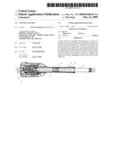
[0008]FIG. 1 shows a longitudinal section through an actuator,
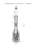
[0009]FIG. 2 shows an enlarged longitudinal section through the area at the main nut,
[0010]FIG. 3 shows a schematic view of the forces at the contact of the safety nut with the threads of the spindle,
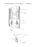
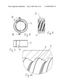
[0011]FIG. 4 shows the main nut seen from the side,
[0012]FIG. 5 shows a longitudinal section through the main nut, shown with a portion of the spindle and with a safety nut at each end,
[0013]FIG. 6 shows a cross-section through the main nut,
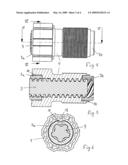
[0014]FIG. 7 shows the safety nut seem from the side,
[0015]FIG. 8 shows the safety nut seen from one end,
[0016]FIG. 9 shows a longitudinal section through the safety nut, and
[0017]FIG. 10 shows an enlarged section at the side of the safety nut.
[0018]As will appear from FIG. 1, the actuator comprises a reversible electric motor 1 which, via a transmission 2, drives a spindle 3 on which a main nut 4 secured against rotation is provided, so that the nut is moved out or in on the spindle depending on the direction of rotation of the spindle. A tubular thrust rod 6, guided in an outer pipe 5, is secured to the main nut 4, said thrust rod being extended from or retracted into the outer pipe 5 by the movement of the nut. The actuator concerned is intended to accommodate pressure loads.
[0019]It appears from the detailed view in FIG. 2 that a safety nut 7 is provided in a well 10 at the end of the main nut 4, said safety nut being secured against rotation relative to the main nut in such a manner that it follows the main nut as a slave, as long as the threads of the main nut are intact and are out of engagement with the threads of the spindle. With reference to FIGS. 5-8, the safety nut 7 is secured in that it is provided with a non-through groove 11 which is arranged inwardly over a fin 12 in the well 10. When the groove 11 is not through-going, easy and correct mounting of the safety nut is ensured.
[0020]As will appear, the spindle 3 is provided with external trapezoidal threads, and the main nut 4 has internal threads corresponding thereto.
[0021]The safety nut 7 has specially configured internal threads. A first flank 8 of the threads corresponds to the threads of the spindle. A second flank 9 of the threads, on the other hand, forms an acute angle v with the longitudinal axis of the nut, that is the flank is steep.
[0022]If the threads of the main nut fail, e.g. because of abnormal wear or material defect, the load on the thrust rod 6 will cause the spindle nut and thereby the safety nut 7 to sag, i.e. slide slightly back so that the steep flank 9 of the safety nut gets into contact with the outer edge of the spindle threads flank facing away from the actuator. The safety nut hereby takes over the load.
[0023]As will appear from the schematic drawing in FIG. 3, a great power component occurs in the contact with the steep flank, resulting in a great frictional force. This ensures the safe state that the actuator can hold the load, but not lift it. The user will see that the thrust rod stands still because the connection of the safety nut with the main nut has been interrupted and the safety nut participates in the rotation of the spindle. If the load is lowered, i.e. the thrust rod is retracted, then the spindle will run free of the steep flank of the safety nut, and the load is now carried on the first flank of the safety nut in engagement with the threads of the spindle.
[0024]Provisional tests have shown that an angle v of 20°-30° gives the desired frictional force.
[0025]It will be appreciated that the invention also applies to actuators which are under tension, the safety nut then just has to be moved to the other side of the main nut. It is evident that a respective safety nut 7a, 7b may be arranged, if the actuator is under pressure as well as tension, cf. the embodiment shown in FIGS. 4-6.
[0026]An actuator has been described in the foregoing, where a tubular thrust rod guided in a guide profile is secured to the spindle nut. It will be appreciated that, alternatively, the actuator may be constructed without an thrust rod, but where the nut is secured directly to the structure in which the actuator is incorporated, as is known e.g. from DK 174 457 B1 to Linak A/S.
Claims:
1. A linear actuator comprising a spindle (3) provided with external
threads, a main nut (4) provided with internal threads and in engagement
with the threads of the spindle, a safety nut (7) arranged in connection
with the main nut (4) and provided with internal threads adapted such
that, in case of an intact main nut, it is not in carrying contact with
the threads of the spindle, said threads of the safety nut having a first
flank (8) intended to engage the threads of the spindle in the event that
the carrying capacity of the main nut fails, characterized in that the
second flank (9) of the safety nut (7) is steep, i.e. forms an acute
angle with the longitudinal axis of the nut.
2. An actuator according to claim 1, characterized in that the acute angle v is of the order of 30.degree..
3. An actuator according to claim 1, characterized in that the safety nut (7) is of metal with hardened threads.
4. An actuator according to claim 1, characterized in that the safety nut (7) is mounted in a well (10) at the end of the main nut (4), that an axially extending fin (12) is provided in the well, and that a groove (11) is provided in the safety nut (7) to receive the fin (12), said groove (11) extending from one end of the safety nut only over a portion of the height of it.
5. An actuator according to claim 1, characterized in that a safety nut (7a, 7b) is provided at each end of the main nut (4).
Description:
[0001]The present invention relates to a linear actuator of the type
defined in the introductory portion of claim 1.
[0002]EP 0 586 326 B1 and EP 1 134 454 B1, both to Linak A/S, disclose linear actuators of the type mentioned initially, which are provided with a safety nut which is connected with the main nut and follows it as a slave as long as the main nut is intact. In the event that the main nut fails, the connection is interrupted, whereby the safety nut takes over the load. Both structures are configured such that the safety nut can only move the load in the direction of loading. In case of e.g. a pressure load, the actuator is not capable of lifting the load, but exclusively to lower it.
[0003]The object of the invention is to provide an improved effect of the safety nut.
[0004]This object is achieved according to the invention by constructing the actuator as stated in the characterizing portion of claim 1. When the second flank of the safety nut is made steep, i.e. forms an acute angle with its longitudinal axis, a great frictional force is provided by engagement with the threads of the spindle in the event that the main nut fails. The great frictional force results from the fact that the threads of the spindle, exclusively with the outer edge, get into point-shaped engagement with the steep flank of the safety nut. The point-shaped engagement is rather a linear engagement seen over the entire threads of the safety nut.
[0005]In the event that the spindle is of steel and the safety nut is likewise of steel, it is expedient to harden the safety nut to avoid the situation that the spindle destroys the nut by abrasion.
[0006]The safety nut may be caused to follow the main nut in different ways. In an embodiment, the safety nut is placed in a well at the end of the main nut, an axially extending fin being provided in the well. The safety nut is provided with a corresponding groove to receive the fin. When the groove is not through-going, but only extends over a portion of the height of the safety nut, correct mounting of the safety nut is ensured in a simple manner.
[0007]Additional features of the invention will appear from the following embodiment of the invention, which will be described more fully below with reference to the accompanying drawing, in which:
[0008]FIG. 1 shows a longitudinal section through an actuator,
[0009]FIG. 2 shows an enlarged longitudinal section through the area at the main nut,
[0010]FIG. 3 shows a schematic view of the forces at the contact of the safety nut with the threads of the spindle,
[0011]FIG. 4 shows the main nut seen from the side,
[0012]FIG. 5 shows a longitudinal section through the main nut, shown with a portion of the spindle and with a safety nut at each end,
[0013]FIG. 6 shows a cross-section through the main nut,
[0014]FIG. 7 shows the safety nut seem from the side,
[0015]FIG. 8 shows the safety nut seen from one end,
[0016]FIG. 9 shows a longitudinal section through the safety nut, and
[0017]FIG. 10 shows an enlarged section at the side of the safety nut.
[0018]As will appear from FIG. 1, the actuator comprises a reversible electric motor 1 which, via a transmission 2, drives a spindle 3 on which a main nut 4 secured against rotation is provided, so that the nut is moved out or in on the spindle depending on the direction of rotation of the spindle. A tubular thrust rod 6, guided in an outer pipe 5, is secured to the main nut 4, said thrust rod being extended from or retracted into the outer pipe 5 by the movement of the nut. The actuator concerned is intended to accommodate pressure loads.
[0019]It appears from the detailed view in FIG. 2 that a safety nut 7 is provided in a well 10 at the end of the main nut 4, said safety nut being secured against rotation relative to the main nut in such a manner that it follows the main nut as a slave, as long as the threads of the main nut are intact and are out of engagement with the threads of the spindle. With reference to FIGS. 5-8, the safety nut 7 is secured in that it is provided with a non-through groove 11 which is arranged inwardly over a fin 12 in the well 10. When the groove 11 is not through-going, easy and correct mounting of the safety nut is ensured.
[0020]As will appear, the spindle 3 is provided with external trapezoidal threads, and the main nut 4 has internal threads corresponding thereto.
[0021]The safety nut 7 has specially configured internal threads. A first flank 8 of the threads corresponds to the threads of the spindle. A second flank 9 of the threads, on the other hand, forms an acute angle v with the longitudinal axis of the nut, that is the flank is steep.
[0022]If the threads of the main nut fail, e.g. because of abnormal wear or material defect, the load on the thrust rod 6 will cause the spindle nut and thereby the safety nut 7 to sag, i.e. slide slightly back so that the steep flank 9 of the safety nut gets into contact with the outer edge of the spindle threads flank facing away from the actuator. The safety nut hereby takes over the load.
[0023]As will appear from the schematic drawing in FIG. 3, a great power component occurs in the contact with the steep flank, resulting in a great frictional force. This ensures the safe state that the actuator can hold the load, but not lift it. The user will see that the thrust rod stands still because the connection of the safety nut with the main nut has been interrupted and the safety nut participates in the rotation of the spindle. If the load is lowered, i.e. the thrust rod is retracted, then the spindle will run free of the steep flank of the safety nut, and the load is now carried on the first flank of the safety nut in engagement with the threads of the spindle.
[0024]Provisional tests have shown that an angle v of 20°-30° gives the desired frictional force.
[0025]It will be appreciated that the invention also applies to actuators which are under tension, the safety nut then just has to be moved to the other side of the main nut. It is evident that a respective safety nut 7a, 7b may be arranged, if the actuator is under pressure as well as tension, cf. the embodiment shown in FIGS. 4-6.
[0026]An actuator has been described in the foregoing, where a tubular thrust rod guided in a guide profile is secured to the spindle nut. It will be appreciated that, alternatively, the actuator may be constructed without an thrust rod, but where the nut is secured directly to the structure in which the actuator is incorporated, as is known e.g. from DK 174 457 B1 to Linak A/S.
User Contributions:
Comment about this patent or add new information about this topic:
Images included with this patent application:
 |  |
 |  |
 |
| Similar patent applications: | |
| Date | Title |
|---|---|
| 2009-10-08 | Linear actuator |
| 2009-10-08 | Linear actuator |
| 2009-10-08 | Linear actuator |
| 2009-11-26 | Electric linear actuator |
| 2009-12-03 | Linear actuator |
| New patent applications in this class: | |
| Date | Title |
|---|---|
| 2011-03-03 | Aircraft stabilizer actuator |
| 2010-09-30 | Direct drive electromechanical linear actuators |
| 2010-02-04 | Actuator |
| 2009-10-22 | actuator with a main rod and an auxiliary rod |
| Top Inventors for class "Machine element or mechanism" | |
| Rank | Inventor's name |
|---|---|
| 1 | Yoshimitsu Miki |
| 2 | Bo Long |
| 3 | Matthias Reisch |
| 4 | Wolfgang Rieger |
| 5 | Craig S. Ross |