Patent application title: BOTTLE AND CAP DEVICE
Inventors:
Larry Brand (Milwaukee, WI, US)
Erik Lomas (Milwaukee, WI, US)
Robert S. Ricci (Milwaukee, WI, US)
Assignees:
Sigma Aldrich Company
IPC8 Class: AB65D4100FI
USPC Class:
215247
Class name: Bottles and jars closures self-sealing, piercable-type closure
Publication date: 2009-04-30
Patent application number: 20090107948
s provided that includes a cap, a septum, and a
container that individually and collectively improves the capacity of the
assembly to securely contain substances. The cap includes internal
threads that mate external threads of the container containing the
substance. The cap further includes flexible teeth for engaging rigid
lugs that are molded into the finish on the neck of the container. The
septum sealably fits between the cap and within an opening of the
container to provide barrier between the contained substance and the
surrounding environment.Claims:
1. A cap and bottle device for containing a substance, the device
comprising:a bottle comprising a neck and a base, the neck comprising
external threads along an outer surface and a plurality of protrusions
spaced circumferentially around the outer surfaces below the external
threads;a cap comprising a circular top and a cylindrical wall depending
from the circular top, the cylindrical wall comprising internal threads
along an inner surface of the cylindrical wall, designed and dimensioned
to match the external threads, and comprising a plurality of indentations
spaced circumferentially along the inner wall that are designed and
dimensioned to align with the plurality of protrusions; anda septum
comprising a flange portion designed and dimensioned to fit above the
neck and a protruding cylindrical plug portion designed and dimensioned
to sealably engage an inner surface of the neck.
2. The cap and bottle device of claim 1 wherein plurality of the indentations are configured to engage the plurality of protrusions to prevent unintentional loosening of a threading connection between the cap and bottle.
3. The cap and bottle device of claim 1 wherein the plurality of the indentations are designed to slip over the plurality of protrusions when the cap is rotated downward and are designed to engage the plurality of protrusions when the cap is rotated upward.
4. The cap and bottle device of claim 1 wherein substance is a liquid or a gas.
5. The cap and bottle device of claim 1 wherein the bottle is selected from a vial or a beaker.
6. The cap and bottle device of claim 1 wherein the septum comprises an inner core and an outer liner, the inner core being formed from a chemically resistant molded elastomer and the outer liner being formed from a chemically inert formed polymer.
7. The cap and bottle device of claim 6 wherein the chemically resistant polymer is selected from at least one of the following polytetrafluoroethylene (PTFE), fluorinated ethylene-propylene (FEP), or perfluoroalkoxy polymer resin (PFA).
8. The cap and bottle device of claim 6 wherein the chemically inert molded elastomer is selected from at least one of the following fluorinated elastomers (FKM), perfluoro elastomers (FFKM), ethylene propylene diene monomer (EPDM).
9. A cap and bottle device for sealably storing a substance, the device having:a container having a neck and a base, the neck comprising a first mechanical connection and a second mechanical connection along an outer surface of the neck;a cap adapted for mating with the first mechanical connection and adapted for engaging the second mechanical connection; anda septum having a substantially flat top surface and having a protruding bottom surface, wherein the top surface is designed to fit within cap, and wherein the bottom surface is designed to sealably engage an inner surface of the neck.
10. The cap and bottle device of claim 9 wherein:the first mechanical connection comprises external threads and the second mechanical connection comprises a plurality of protrusions spaced circumferentially around the outer surface of the neck below the external threads; andthe cap comprises a circular top and a cylindrical wall depending from the circular top, the cylindrical wall comprising internal threads along an inner surface of the cylindrical wall, designed and dimensioned to mate with the external threads and comprising a plurality of indentations spaced circumferentially along the inner wall that are designed and dimensioned to align with the plurality of protrusions to prevent unintentional loosening of a threaded connection between the cap and container.
11. The cap and bottle device of claim 10 wherein the plurality of the indentations are designed to slip over the plurality of protrusions when the cap is rotated downward and are designed to engage the plurality of protrusions when the cap is rotated upward.
12. The cap and bottle device of claim 9 wherein substance is a liquid or a gas.
13. The cap and bottle device of claim 9 wherein the container is selected from a bottle; a vial; or a beaker.
14. The cap and bottle device of claim 9 wherein the septum comprises an inner core and an outer liner, the inner core being formed from a chemically resistant molded elastomer and the outer liner being formed from a chemically inert formed polymer.
15. The cap and bottle device of claim 14 wherein the chemically resistant polymer is selected from at least one of the following polytetrafluoroethylene (PTFE), fluorinated ethylene-propylene (FEP), or perfluoroalkoxy polymer resin (PFA).
16. The cap and bottle device of claim 14 wherein the chemically inert molded elastomer is selected from at least one of the following fluorinated elastomers (FKM), perfluoro elastomers (FFKM), ethylene propylene diene monomer (EPDM).
17. A cap and bottle device for containing a substance, the device comprising:a container comprising a neck and a base, the neck comprising external threads along an outer surface of the neck and a plurality of protrusions spaced circumferentially around the outer surfaces below the external threads;a cap comprising a body member and a lid member, the body member comprising a circular top and a cylindrical wall depending from the circular top, the cylindrical wall comprising internal threads along an inner surface of the cylindrical wall designed and dimensioned to match the external threads and comprising a plurality of indentations spaced circumferentially along the inner wall that are designed and dimensioned to align with the plurality of protrusions; anda septum comprising a flange portion designed and dimensioned to fit above the neck and a protruding cylindrical plug portion designed and dimensioned to sealably engage an inner wall of the neck.
18. The cap and bottle device of claim 17 further comprising a flexible tether integrally connected to the body member and the lid member, wherein the circular top comprises an access port to provide access to the septum, and wherein the lid member is designed to lift away from the body member to reveal the access port.
19. The cap and bottle device of claim 17 wherein plurality of the indentations are configured to engage the plurality of protrusions to prevent unintentional loosening of a threading connection between the cap and container.
20. The cap and bottle device of claim 17 wherein the plurality of the indentations are designed to slip over the plurality of protrusions when the cap is rotated downward and are designed to engage the plurality of protrusions when the cap is rotated upward.
21. The cap and bottle device of claim 17 wherein the container is selected from a bottle; a vial; or a beaker.
22. The cap and bottle device of claim 17 wherein the septum comprises an inner core and an outer liner, the inner core being formed from a chemically resistant molded elastomer and the outer liner being formed from a chemically inert formed polymer.
23. The cap and bottle device of claim 22 wherein the chemically resistant polymer is selected from at least one of the following polytetrafluoroethylene (PTFE), fluorinated ethylene-propylene (FEP), or perfluoroalkoxy polymer resin (PFA).
24. The cap and bottle device of claim 22 wherein the chemically inert molded elastomer is selected from at least one of the following fluorinated elastomers (FKM), perfluoro elastomers (FFKM), ethylene propylene diene monomer (EPDM).
25. A cap and bottle device for containing a substance, the device comprising:a bottle comprising a neck and a base, the neck comprising external threads along an outer surface and a plurality of protrusions spaced circumferentially around the outer surfaces below the external threads;a cap comprising a circular top and a cylindrical wall depending from the circular top, the cylindrical wall comprising internal threads along an inner surface of the cylindrical wall, designed and dimensioned to match the external threads and comprising a plurality of indentations spaced circumferentially along the inner wall that are designed and dimensioned to align with the plurality of protrusions; anda septum designed to fit within the cap and to seal an open end of the bottle.Description:
TECHNICAL FIELD
[0001]The invention relates to a cap and bottle device for providing secure containment of substances. More particularly, the invention relates to an improved cap and bottle device for preventing exposure of contained substances to the surrounding environment.
BACKGROUND
[0002]Cap and bottle devices are used in various industries for storing substances such liquids and/or gases that require isolation from the environment. For example, cap and bottle devices are used in the medical industry to provide a sterile environment for storing medications and/or biological samples. As another example, cap and bottle devices are used in the chemical industry to provide a secure means for storing and transporting liquids or gases, including hazardous compositions.
[0003]In general, cap and bottle devices include a cap, a septum, and a bottle. The cap may be, for example, a threaded cap adapted to mate with threads on the bottle such that the cap can be mechanically attached to the bottle. The bottle can be a vial, a beaker, or any other vessel that can store liquids or fluids or gases and that can be attached to a cap. The septum fits between the cap and the bottle. The purpose of the septum is to prevent leakage of the substance stored in the bottle and to maintain a barrier between the substance and the surrounding environment.
[0004]In order to access the substances stored in a cap and bottle device with minimal exposure to the surrounding environment, an access port incorporated into the closure component is removed and a cannula or syringe needle can be used to pierce the septum such that substances can be injected into or extracted out of the bottle. However, when a substance in a bottle has been accessed by a cannula or when the cap has been removed from the bottle for extended periods, the septum can become permeable, which can lead to inadvertent exposure of the contained substance to the surrounding environment. As a result of the exposure to the environment, the contained substance can evaporate, degrade, leak into the environment, become contaminated, or some combination thereof. Furthermore, exposure of the contained substance to atmospheric air can cause unsightly rusting or discoloration of the cap and bottle device. In particular, exposure can cause degradation of chemical components.
[0005]Moreover, even when the closure component has not been removed from the containment component, changes in the surrounding environment such as, for example, temperature, atmospheric pressure, vibration during transportation, or a combination thereof, can lead to premature loosening or degradation of the threaded connection between the cap and containment component. This premature loosening, or cap back-off, of the closure component from the containment component can also lead to inadvertent exposure of the contained substance to the surrounding environment.
[0006]As such, there is a need for cap and bottle device that addresses these problems and other problems associated with conventional containment assemblies.
SUMMARY
[0007]In an embodiment, a cap and bottle device is specified for containing a substance. The device includes a bottle having a neck and a base. The neck comprises external threads along an outer surface and a plurality of protrusions spaced circumferentially around the outer surfaces below the external threads. The device includes a cap comprising a circular top and a cylindrical wall depending from the circular top. The cylindrical wall has internal threads along an inner surface of the cylindrical wall that are designed and dimensioned to match the external thread. The cylindrical wall includes a plurality of indentations that are spaced circumferentially along the inner wall and that are designed and dimensioned to align with the plurality of protrusions. The device includes a septum having a flange portion designed and dimensioned to fit above the neck and a protruding cylindrical plug portion designed and dimensioned to sealably engage an inner surface of the neck.
[0008]In another embodiment, a cap and bottle device is specified for sealably storing a substance. The device includes a container having a neck and a base. The neck comprises a first mechanical connection and a second mechanical connection along an outer surface of the neck. The device also includes a cap adapted for mating with the first mechanical connection and adapted for engaging the second mechanical connection. The device further includes a septum having a substantially flat top surface and having a protruding bottom surface. The top surface is designed to fit within cap and the bottom surface is designed to sealably engage an inner surface of the neck.
[0009]In another embodiment, a cap and bottle device is specified for containing a substance. The neck comprises external threads along an outer surface and a plurality of protrusions spaced circumferentially around the outer surfaces below the external threads. The device also includes a cap comprising a body member and a lid member. The body member comprises a circular top and a cylindrical wall depending from the circular top. The cylindrical wall includes a plurality of indentations that are spaced circumferentially along the inner wall and that are designed and dimensioned to align with the plurality of protrusions. The device includes a septum having a flange portion designed and dimensioned to fit above the neck and a protruding cylindrical plug portion designed and dimensioned to sealably engage an inner surface of the neck.
[0010]In another embodiment, a cap and bottle device is provided for containing a substance. The device includes a bottle comprising a neck and a base, the neck comprising external threads along an outer surface and a plurality of protrusions spaced circumferentially around the outer surfaces below the external threads. The device also includes a cap comprising a circular top and a cylindrical wall depending from the circular top. The cylindrical wall comprises internal threads along an inner surface of the cylindrical wall that are designed and dimensioned to match the external threads and comprises a plurality of indentations spaced circumferentially along the inner wall that are designed and dimensioned to align with the plurality of protrusions. The device also includes a septum designed to fit within cap and to seal an open end of the bottle.
[0011]Additional objectives, advantages and novel features will be set forth in the description which follows or will become apparent to those skilled in the art, upon examination of the drawings and detailed description which follows.
BRIEF DESCRIPTION OF THE DRAWINGS
[0012]FIG. 1 is an illustration of an unassembled cap and bottle device;
[0013]FIG. 2A is a cross-sectional view of a cap of the cap and bottle device;
[0014]FIG. 2B is a cross-sectional top view and a side view of a tamper-evidence portion the cap and bottle device;
[0015]FIG. 3 is a cross-sectional view of a bottle of the cap and bottle device;
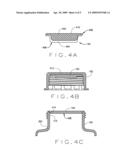
[0016]FIG. 4A is a cross-sectional view of a septum of the cap and bottle device;
[0017]FIG. 4B is a cross-sectional view of the septum disposed within the cap;
[0018]FIG. 4C is a cross-sectional view of the septum disposed within the bottle; and
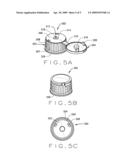
[0019]FIGS. 5A-5C are isometric views of an alternative cap of the cap and bottle device.
[0020]Corresponding reference characters indicate corresponding elements among the several views. The headings used in the figures should not be interpreted to limit the scope of the figures.
DETAILED DESCRIPTION
[0021]As described above, containment assemblies are used in various industries for storing substances such as liquids, fluids, or gases that require isolation from the environment. According to the present invention, a cap and bottle device is provided that includes a cap, liner, and bottle that individually and collectively contribute to an improved cap and bottle device for preventing exposure of contained substances to the surrounding environment and for allowing the contained substance to be accessed via a cannula or syringe needle while maintaining a sealed barrier between the substance and surrounding environment. For example, in addition to the cap and bottle being adapted to connect to each other, the cap and bottle are further adapted to prevent premature loosening of the connection, or cap back-off, which can occur as a result of material relaxation or environmental conditions. Moreover, as will be explained in greater detail below, the septum (i.e., liner) includes a plug-style design that provides several advantages over conventional septa.
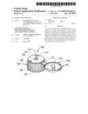
[0022]Referring now to FIG. 1, an isometric view of an unassembled cap and bottle device 100 is shown. Structurally, the cap and bottle device 100 consists of a cap 102, a septum 104, and a bottle 106 that can facilitate secure storage of substances such as liquids, gases, or fluids. Although the cap 102, septum 104, and bottle 106 individually contribute to providing an improved sealable cap and bottle device 100, the combination of these components provides an even more effective cap and bottle device 100 for containing substances and for preventing environmental contamination of such substances.
[0023]The bottle 106 can be vial, beaker, or any other vessel that can store liquids, fluids, or gases or a combination. The bottle 106 can be made from glass, plastic, polymer, or any other suitable material appropriate for storing chemical substances. According to one aspect, the bottle 106 comprises a cylindrical neck 108 and a cylindrically shaped base 110 that depends from the neck 108. The base 110 provides the primary containment area for the substance and provides support for the bottle 106. The base can be of a variety of shapes and sizes including rectangular, triangular, etc. so long as materials are adequately held. Threads 112 are formed on an outer surface of the neck 108 to enable the bottle 106 to be threaded into and out of the cap 102. The inner surface 114 of the neck 108 defines an opening or mouth of the bottle 106. The surface can be continuously smooth wall. Although the shape of the neck 108 and base 110 of the bottle 106 are depicted and described as being substantially cylindrical, it is contemplated that the neck 108 and base 110 can have other suitable shapes.
[0024]A plurality of protrusions 116 are molded into the finish of the bottle 106 circumferentially along the outer surface of the neck 108 below the threads 112 and above the base 110. As described in more detail below, the plurality of protrusions provide a means for opposing an unintentional upward rotation (e.g., loosening) of the threaded connection between the cap 102 and bottle 106 that may result from environmental changes or material relaxation. The protrusions 116 can be cylindrical and are made from the same material as the bottle or cap, alternatively the protrusions 116 can be a single annulus.
[0025]According to one aspect, the cap 102 is a structure having a substantially cylindrical shape comprising a circular top 118, and having a substantially cylindrically outer shaped wall 120 depending from the periphery of the top 118. The cap 102 can be made from any suitable material such as plastic. This plastic material may be polypropylene, polyethylene, polyester, polysulphone, a polycarbonate, phenolic plastic, fluoropolymer, or any other suitable plastic material. The cap 102 can be mechanically connected to the bottle 106 via a suitable joining means. For example, as explained in more detail in reference to FIG. 2 below, an inner surface of the wall 110 may comprise threads that are that are designed and dimensioned to match threads of the bottle 106 such that the cap 102 to be attached to the bottle 106.
[0026]According to another aspect, the cap 102 can be lockingly engaged with the bottle 106 to prevent premature loosening, or cap back-off, of a threaded connection between the cap 102 and the bottle 106. As explained in more detail below in reference to FIG. 2 below, the cap 102 can comprise flexible locking members or indentations (see 206 in FIG. 2) that are designed and dimensioned to align with the plurality of protrusions 116 that are incorporated onto the outer surface finish of the bottle 106. For example, the locking members are designed to slip over the plurality of the protrusions 116 to be received by the locking members 206, when the cap 102 is rotated downward (e.g., clockwise), and are designed to engage the plurality of protrusions 116 when the cap 102 is rotated upward (e.g., counter clockwise) to prevent unintentional loosening of the threaded connection that could result, due to environmental changes and/or material relaxation. In other words, due to the locking members and protrusions, the cap 102 operates in a ratchet like manner. That is, when the cap 102 is rotated downward, the locking member raises or slips over the protusion and then clicks back in place. However, the locking member is designed and dimensioned to engage the protrustions 116 when rotating the cap 102 upward, such that it is difficult to remove the cap 102.
[0027]According to one aspect, the septum 104 is formed from a resilient elastomeric material that can be pierced, for example, by a liquid injection or extraction device, such as a syringe needle. This allows for the injection of liquids into the bottle 106 or the extraction of liquids out of the bottle 106. Because the septum 104 is elastomeric, after being pierced by the needle, the septum 104 is disposed in a sealed engagement circumferentially around the needle. This engagement prevents leakage of the substance from the container and prevents leakage of the atmosphere into the container.
[0028]The septum comprises an upper flange portion 122 and a lower cylindrical plug portion 124. The combined thickness of the flange portion 122 and cylindrical portion 124 provides a septum 104 that does not collapse during piercing by the syringe needle. The cylindrical portion is designed and dimensioned to be received by the inner wall of the neck 108. Furthermore, after the needle is removed from the septum, the extended thickness allows for more effective resealing of the elastomeric material.
[0029]Prior to connecting the cap 102 to the bottle 106, the lower cylindrical portion 124 of the septum 104 is designed and dimensioned to sealably engage the inner surface 114 of the neck 108 of the bottle 106. As such, this will be a permanent placement into the neck cavity.
[0030]During installation of the cap 102 onto the bottle 106, the cap 102 is rotated, clockwise for example, to allow the threads of the cap 102 to engage the threads 112 on the neck 116 of the bottle 106. After the cap 102 has been sufficiently rotated downward, the locking members (see FIG. 2A) of the cap 102 align with the plurality of protrusions 116 of the bottle 106 to prevent cap back-off. In essence, this holds the cap in a fixed position and prevents upward movement away from the bottle.
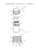
[0031]Referring now to FIG. 2A, a cross-sectional view of the cap 102 is shown. As described above, the cap 102 includes a circular top 118 and a cylindrical wall 120 that depends from and is integral with circular top 118. An inner surface 202 of the wall of the cap 102 comprises threads 204 that are designed and dimensioned to align with threads 112 of the bottle 106. The circumference can be of a variety of dimensions so long as it matches with the bottle.
[0032]A plurality of indentations 206 are spaced along the circumference of the inner surface 202 between a bottom edge 208 of the cap 102 and the threads 204. The plurality of indentations 206 are designed and dimensioned to engage the plurality of protrusions 116 incorporated within the surface finish of the bottle 106 to prevent unintentional loosening of the threaded connection between the cap 102 and bottle 106.
[0033]According to one aspect, the plurality of indentations 206 are incorporated into a tamper-evident portion 210 of the cap 102. The tamper-evident portion 210 corresponds to a lower portion of the cap that is attached to an upper portion of the cap 102 via a plurality of frangible connections (not shown) extending around at least a portion of the circumference of the tamper-evident portion 208.
[0034]Referring now to FIG. 2B, there is shown a cross sectional top view 212 and a side view 214 of the tamper-evident portion 210 according to one aspect of the cap and bottle assembly. The tamper-evident portion or band 210 includes eight (8) ratcheting teeth (e.g., indentations or locking members 206) spaced at approximately forty-five degrees (45°) intervals. However, it is contemplated that in other embodiments, more or less teeth may be required. For example, the number of teeth may vary based on based thread pitch and torque specifications tolerances. The locking members 210 need not be configured in evenly spaced intervals, but the locking members 210 should be in groups designed and dimensioned to align with the plurality of protrusions
[0035]The frangible connections are formed, for example, by thin wall segments, which have sufficient shear resistance to withstand the rotational forces, imposed when the cap 102 is being threaded onto the bottle 106, or imposed as a result of unintentional upward rotation (e.g., loosening) of the threaded connection between the cap 102 and bottle 106 that result from environmental changes and/or material relaxation. However, when the cap 102 is manually rotated upward with sufficient rotational torque, the plurality of indentations 206 engage the plurality of protrusions 116 and the frangible connections break such that the tamper-evident portions 210 breaks away from the cap 102 to provide evidence that the cap 102 was removed or that there was an attempt to remove the cap 102.
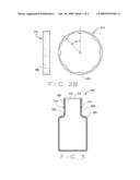
[0036]Referring now to FIG. 3, a cross-sectional view of the bottle 106 is shown. According to one aspect, the bottle 106 comprises a cylindrical neck 302 (e.g., neck 108) and a cylindrically-shaped base 304 (e.g., base 110) depending from and integral with the neck 302. Exterior threads 306 (e.g., threads 112) are formed onto the exterior wall 308 of the neck 302 to enable the bottle 106 to be screwed into the cap 102. The inner wall 310 of the neck 302 defines an opening 312 or mouth of the bottle 106. A plurality of protrusions 314 (e.g., protrusions 116) are molded into the finish of the bottle 106 along the outer circumference of the neck 302 below the external threads 306 and above the base 304. The protrusions can be of a variety of sizes and dimensions, so long as they can be received and held by the cap indentions. Moreover, the number of protrustions along the outer circumference of the neck 302 can vary. For example, the bottle may include three protrustions that are spaced at 120 degree intervals along the outer circumference of the neck 302. Alternatively, the bottle may include four protrustions that are spaced at 90 degree intervals along the outer circumference of the neck 302.
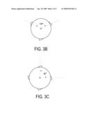
[0037]Referring now to FIG. 4A, a cross-sectional view of the septum 104 is shown. According to one embodiment, the septum 104 comprises a septum core 402 that is bonded to a septum liner 404. The septum core 402 can be formed from a chemically resistant elastomer and the septum liner 404 can be formed from a chemically inert formed polymer. The chemically resistant polymer liner facing 404 serves as a primary barrier to gas and liquid flux. Examples of chemically resistant polymers include polytetra-fluoroethylene (PTFE), fluorinated ethylene-propylene (FEP), or perfluoroalkoxy polymer resin (PFA). The molded elastomer liner 402 provides a secondary barrier that reseals after a needle puncture and that facilitates a leak proof fit to glass defects. In one embodiment, the liner has a thickness range between approximately 4.5-5.5 mils. As used herein, mils refers to a thousandth of an inch. Examples of injection molded elastomers that can be used include polysulfide, butyl rubber, silicone, fluorosilicone, fluorocarbon elastomers (FKM), perfluorocarbon elastomers (FFKM), or ethylene propylene diene monomer (EPDM).
[0038]The septum 104 includes an upper flange portion 406 adapted to fit atop the opening 312 of the bottle 106 and a protruding cylindrical plug portion 408, designed and aligned to compressively within the opening 312 of the bottle 106.
[0039]A top surface 410 of the upper flange portion 406 is substantially flat and configured to fit within the cap 102 and flush with an inner top surface 412 of the cap 102 such as shown in FIG. 4B. A side wall surface 414 of the protruding cylindrical plug portion 408 of the septum 104 is designed and dimensioned to sealably engage the interior, or inner, surface 310 of the neck 302 of the bottle 106 such as shown in FIG. 4C. As such, by positioning the protruding cylindrical portion 408 within the opening 312 of the bottle 106, the septum 104 can be securely affixed to the bottle 106. Although the septum 104 is described herein as comprising an upper flange portion 406 and a protruding plug portion 408, it is contemplated that the septum 104 can have a flat disc shape (e.g., excludes protruding plug portion) according to other aspects the cap and bottle device.
[0040]Referring now to FIGS. 5A and 5B, isometric views of a flip cap 502 that can be used with the cap and bottle device 100 are shown. Similar to the cap 102 described above, the flip cap 502 includes internal threads (see FIG. 5C) formed in the interior wall thereof to enable the flip cap 502 to be mechanically attached to the bottle 106. According to one aspect, the flip cap 502 is a structure having a body 503 and a lid 504. The body 503 has a substantially cylindrical shape comprising a top 506 and having a substantially cylindrically shaped wall 508 depending from the periphery of the top 506. The outer surface of the wall 508 includes a plurality of vertical groves or torque flutes 507 evenly spaced the around the outer circumference of the body 503. The torque flutes 507 can provide additional grip to a user loosening or tightening the cap onto the body.
[0041]A lid 504 is connected to the top 506 via a hinge/tether 510 and can be lifted away from the top 506 to reveal an access port 512 as shown in FIG. 5A. According to one embodiment, the tether 510 is molded to the cylindrical wall 508 of the flip cap 502. The access port 512 allows the septum 104 to be accessed without removing the cap 502. For example, a cannula can pass through the access port 512 and penetrate the septum 104 to transfer liquid into or out of the bottle 106. As a result, the flip cap 502 provides a secondary barrier against oxygen and moisture, as well as against airborne particulates such as dust and other contaminants.
[0042]According to one embodiment, an annular opening 514 within the top 506 of the cap 102 defines the access port 512. The lid 504 includes a plug 516 that can be pushed downward with an axial downward force to engage an inner wall 518 of the annular opening 514 to seal the lid 504 in a locked position as shown in FIG. 5B.
[0043]FIG. 5C shows a bottom view of the interior of the flip cap 502. An interior surface 520 of the substantially cylindrically shaped wall 508 of the flip cap 502 comprises threads 522. By means of the threads 522, the flip cap 502 can be screwed onto the neck 302 of the bottle 106. The flip cap 502 further comprises locking members 524 that are formed along the bottom periphery, as indicated by 520, of the flip cap 502. The locking members 524 are configured to engage the plurality of axial ridges incorporated within the surface finish of the bottle 106 to prevent loosening of the threaded connection between the flip cap 502 and the bottle 106.
[0044]According to one aspect, the locking members 524 are incorporated into a tamper-evident band 526 of the flip-cap 502. When the cap 502 is manually rotated upward, the locking members 206 engage the plurality of protrusions 314, of the bottle 116. This engagement causes the tamper-evident band 526 to break away from the flip cap 502, and, thus, provides evidence that the flip-cap 502 was removed, or that there was an attempt to remove the cap 502. The tamper-evident band 526 can be configured such as described above in connection with FIG. 2B (i.e., see tamper-evident portion 210)
[0045]According to another aspect, a flip cap 502 can also be used to show evidence of tampering. For example, the lid 502 includes a tamper tab 528 that is configured to engage a recessed portion of the top 506 when the lid 504 is in a closed position (see FIG. 5B). The first time the lid 504 is lifted away from the top 506, the tab 528 breaks away from the lid 504, and, thus, provides evidence that the lid has been opened.
[0046]When introducing elements of aspects of the invention or the embodiments thereof, the articles "a," "an," "the," and "the" are intended to mean that there are one or more of the elements. The terms "comprising," "including," and "having" are intended to be inclusive and mean that there may be additional elements other than the listed elements.
[0047]As various changes could be made in the above designs, constructions, products, and methods without departing from the scope of aspects of the invention, it is intended that all matter contained in the above description and shown in the accompanying drawings shall be interpreted as illustrative and not in a limiting sense.
Claims:
1. A cap and bottle device for containing a substance, the device
comprising:a bottle comprising a neck and a base, the neck comprising
external threads along an outer surface and a plurality of protrusions
spaced circumferentially around the outer surfaces below the external
threads;a cap comprising a circular top and a cylindrical wall depending
from the circular top, the cylindrical wall comprising internal threads
along an inner surface of the cylindrical wall, designed and dimensioned
to match the external threads, and comprising a plurality of indentations
spaced circumferentially along the inner wall that are designed and
dimensioned to align with the plurality of protrusions; anda septum
comprising a flange portion designed and dimensioned to fit above the
neck and a protruding cylindrical plug portion designed and dimensioned
to sealably engage an inner surface of the neck.
2. The cap and bottle device of claim 1 wherein plurality of the indentations are configured to engage the plurality of protrusions to prevent unintentional loosening of a threading connection between the cap and bottle.
3. The cap and bottle device of claim 1 wherein the plurality of the indentations are designed to slip over the plurality of protrusions when the cap is rotated downward and are designed to engage the plurality of protrusions when the cap is rotated upward.
4. The cap and bottle device of claim 1 wherein substance is a liquid or a gas.
5. The cap and bottle device of claim 1 wherein the bottle is selected from a vial or a beaker.
6. The cap and bottle device of claim 1 wherein the septum comprises an inner core and an outer liner, the inner core being formed from a chemically resistant molded elastomer and the outer liner being formed from a chemically inert formed polymer.
7. The cap and bottle device of claim 6 wherein the chemically resistant polymer is selected from at least one of the following polytetrafluoroethylene (PTFE), fluorinated ethylene-propylene (FEP), or perfluoroalkoxy polymer resin (PFA).
8. The cap and bottle device of claim 6 wherein the chemically inert molded elastomer is selected from at least one of the following fluorinated elastomers (FKM), perfluoro elastomers (FFKM), ethylene propylene diene monomer (EPDM).
9. A cap and bottle device for sealably storing a substance, the device having:a container having a neck and a base, the neck comprising a first mechanical connection and a second mechanical connection along an outer surface of the neck;a cap adapted for mating with the first mechanical connection and adapted for engaging the second mechanical connection; anda septum having a substantially flat top surface and having a protruding bottom surface, wherein the top surface is designed to fit within cap, and wherein the bottom surface is designed to sealably engage an inner surface of the neck.
10. The cap and bottle device of claim 9 wherein:the first mechanical connection comprises external threads and the second mechanical connection comprises a plurality of protrusions spaced circumferentially around the outer surface of the neck below the external threads; andthe cap comprises a circular top and a cylindrical wall depending from the circular top, the cylindrical wall comprising internal threads along an inner surface of the cylindrical wall, designed and dimensioned to mate with the external threads and comprising a plurality of indentations spaced circumferentially along the inner wall that are designed and dimensioned to align with the plurality of protrusions to prevent unintentional loosening of a threaded connection between the cap and container.
11. The cap and bottle device of claim 10 wherein the plurality of the indentations are designed to slip over the plurality of protrusions when the cap is rotated downward and are designed to engage the plurality of protrusions when the cap is rotated upward.
12. The cap and bottle device of claim 9 wherein substance is a liquid or a gas.
13. The cap and bottle device of claim 9 wherein the container is selected from a bottle; a vial; or a beaker.
14. The cap and bottle device of claim 9 wherein the septum comprises an inner core and an outer liner, the inner core being formed from a chemically resistant molded elastomer and the outer liner being formed from a chemically inert formed polymer.
15. The cap and bottle device of claim 14 wherein the chemically resistant polymer is selected from at least one of the following polytetrafluoroethylene (PTFE), fluorinated ethylene-propylene (FEP), or perfluoroalkoxy polymer resin (PFA).
16. The cap and bottle device of claim 14 wherein the chemically inert molded elastomer is selected from at least one of the following fluorinated elastomers (FKM), perfluoro elastomers (FFKM), ethylene propylene diene monomer (EPDM).
17. A cap and bottle device for containing a substance, the device comprising:a container comprising a neck and a base, the neck comprising external threads along an outer surface of the neck and a plurality of protrusions spaced circumferentially around the outer surfaces below the external threads;a cap comprising a body member and a lid member, the body member comprising a circular top and a cylindrical wall depending from the circular top, the cylindrical wall comprising internal threads along an inner surface of the cylindrical wall designed and dimensioned to match the external threads and comprising a plurality of indentations spaced circumferentially along the inner wall that are designed and dimensioned to align with the plurality of protrusions; anda septum comprising a flange portion designed and dimensioned to fit above the neck and a protruding cylindrical plug portion designed and dimensioned to sealably engage an inner wall of the neck.
18. The cap and bottle device of claim 17 further comprising a flexible tether integrally connected to the body member and the lid member, wherein the circular top comprises an access port to provide access to the septum, and wherein the lid member is designed to lift away from the body member to reveal the access port.
19. The cap and bottle device of claim 17 wherein plurality of the indentations are configured to engage the plurality of protrusions to prevent unintentional loosening of a threading connection between the cap and container.
20. The cap and bottle device of claim 17 wherein the plurality of the indentations are designed to slip over the plurality of protrusions when the cap is rotated downward and are designed to engage the plurality of protrusions when the cap is rotated upward.
21. The cap and bottle device of claim 17 wherein the container is selected from a bottle; a vial; or a beaker.
22. The cap and bottle device of claim 17 wherein the septum comprises an inner core and an outer liner, the inner core being formed from a chemically resistant molded elastomer and the outer liner being formed from a chemically inert formed polymer.
23. The cap and bottle device of claim 22 wherein the chemically resistant polymer is selected from at least one of the following polytetrafluoroethylene (PTFE), fluorinated ethylene-propylene (FEP), or perfluoroalkoxy polymer resin (PFA).
24. The cap and bottle device of claim 22 wherein the chemically inert molded elastomer is selected from at least one of the following fluorinated elastomers (FKM), perfluoro elastomers (FFKM), ethylene propylene diene monomer (EPDM).
25. A cap and bottle device for containing a substance, the device comprising:a bottle comprising a neck and a base, the neck comprising external threads along an outer surface and a plurality of protrusions spaced circumferentially around the outer surfaces below the external threads;a cap comprising a circular top and a cylindrical wall depending from the circular top, the cylindrical wall comprising internal threads along an inner surface of the cylindrical wall, designed and dimensioned to match the external threads and comprising a plurality of indentations spaced circumferentially along the inner wall that are designed and dimensioned to align with the plurality of protrusions; anda septum designed to fit within the cap and to seal an open end of the bottle.
Description:
TECHNICAL FIELD
[0001]The invention relates to a cap and bottle device for providing secure containment of substances. More particularly, the invention relates to an improved cap and bottle device for preventing exposure of contained substances to the surrounding environment.
BACKGROUND
[0002]Cap and bottle devices are used in various industries for storing substances such liquids and/or gases that require isolation from the environment. For example, cap and bottle devices are used in the medical industry to provide a sterile environment for storing medications and/or biological samples. As another example, cap and bottle devices are used in the chemical industry to provide a secure means for storing and transporting liquids or gases, including hazardous compositions.
[0003]In general, cap and bottle devices include a cap, a septum, and a bottle. The cap may be, for example, a threaded cap adapted to mate with threads on the bottle such that the cap can be mechanically attached to the bottle. The bottle can be a vial, a beaker, or any other vessel that can store liquids or fluids or gases and that can be attached to a cap. The septum fits between the cap and the bottle. The purpose of the septum is to prevent leakage of the substance stored in the bottle and to maintain a barrier between the substance and the surrounding environment.
[0004]In order to access the substances stored in a cap and bottle device with minimal exposure to the surrounding environment, an access port incorporated into the closure component is removed and a cannula or syringe needle can be used to pierce the septum such that substances can be injected into or extracted out of the bottle. However, when a substance in a bottle has been accessed by a cannula or when the cap has been removed from the bottle for extended periods, the septum can become permeable, which can lead to inadvertent exposure of the contained substance to the surrounding environment. As a result of the exposure to the environment, the contained substance can evaporate, degrade, leak into the environment, become contaminated, or some combination thereof. Furthermore, exposure of the contained substance to atmospheric air can cause unsightly rusting or discoloration of the cap and bottle device. In particular, exposure can cause degradation of chemical components.
[0005]Moreover, even when the closure component has not been removed from the containment component, changes in the surrounding environment such as, for example, temperature, atmospheric pressure, vibration during transportation, or a combination thereof, can lead to premature loosening or degradation of the threaded connection between the cap and containment component. This premature loosening, or cap back-off, of the closure component from the containment component can also lead to inadvertent exposure of the contained substance to the surrounding environment.
[0006]As such, there is a need for cap and bottle device that addresses these problems and other problems associated with conventional containment assemblies.
SUMMARY
[0007]In an embodiment, a cap and bottle device is specified for containing a substance. The device includes a bottle having a neck and a base. The neck comprises external threads along an outer surface and a plurality of protrusions spaced circumferentially around the outer surfaces below the external threads. The device includes a cap comprising a circular top and a cylindrical wall depending from the circular top. The cylindrical wall has internal threads along an inner surface of the cylindrical wall that are designed and dimensioned to match the external thread. The cylindrical wall includes a plurality of indentations that are spaced circumferentially along the inner wall and that are designed and dimensioned to align with the plurality of protrusions. The device includes a septum having a flange portion designed and dimensioned to fit above the neck and a protruding cylindrical plug portion designed and dimensioned to sealably engage an inner surface of the neck.
[0008]In another embodiment, a cap and bottle device is specified for sealably storing a substance. The device includes a container having a neck and a base. The neck comprises a first mechanical connection and a second mechanical connection along an outer surface of the neck. The device also includes a cap adapted for mating with the first mechanical connection and adapted for engaging the second mechanical connection. The device further includes a septum having a substantially flat top surface and having a protruding bottom surface. The top surface is designed to fit within cap and the bottom surface is designed to sealably engage an inner surface of the neck.
[0009]In another embodiment, a cap and bottle device is specified for containing a substance. The neck comprises external threads along an outer surface and a plurality of protrusions spaced circumferentially around the outer surfaces below the external threads. The device also includes a cap comprising a body member and a lid member. The body member comprises a circular top and a cylindrical wall depending from the circular top. The cylindrical wall includes a plurality of indentations that are spaced circumferentially along the inner wall and that are designed and dimensioned to align with the plurality of protrusions. The device includes a septum having a flange portion designed and dimensioned to fit above the neck and a protruding cylindrical plug portion designed and dimensioned to sealably engage an inner surface of the neck.
[0010]In another embodiment, a cap and bottle device is provided for containing a substance. The device includes a bottle comprising a neck and a base, the neck comprising external threads along an outer surface and a plurality of protrusions spaced circumferentially around the outer surfaces below the external threads. The device also includes a cap comprising a circular top and a cylindrical wall depending from the circular top. The cylindrical wall comprises internal threads along an inner surface of the cylindrical wall that are designed and dimensioned to match the external threads and comprises a plurality of indentations spaced circumferentially along the inner wall that are designed and dimensioned to align with the plurality of protrusions. The device also includes a septum designed to fit within cap and to seal an open end of the bottle.
[0011]Additional objectives, advantages and novel features will be set forth in the description which follows or will become apparent to those skilled in the art, upon examination of the drawings and detailed description which follows.
BRIEF DESCRIPTION OF THE DRAWINGS
[0012]FIG. 1 is an illustration of an unassembled cap and bottle device;
[0013]FIG. 2A is a cross-sectional view of a cap of the cap and bottle device;
[0014]FIG. 2B is a cross-sectional top view and a side view of a tamper-evidence portion the cap and bottle device;
[0015]FIG. 3 is a cross-sectional view of a bottle of the cap and bottle device;
[0016]FIG. 4A is a cross-sectional view of a septum of the cap and bottle device;
[0017]FIG. 4B is a cross-sectional view of the septum disposed within the cap;
[0018]FIG. 4C is a cross-sectional view of the septum disposed within the bottle; and
[0019]FIGS. 5A-5C are isometric views of an alternative cap of the cap and bottle device.
[0020]Corresponding reference characters indicate corresponding elements among the several views. The headings used in the figures should not be interpreted to limit the scope of the figures.
DETAILED DESCRIPTION
[0021]As described above, containment assemblies are used in various industries for storing substances such as liquids, fluids, or gases that require isolation from the environment. According to the present invention, a cap and bottle device is provided that includes a cap, liner, and bottle that individually and collectively contribute to an improved cap and bottle device for preventing exposure of contained substances to the surrounding environment and for allowing the contained substance to be accessed via a cannula or syringe needle while maintaining a sealed barrier between the substance and surrounding environment. For example, in addition to the cap and bottle being adapted to connect to each other, the cap and bottle are further adapted to prevent premature loosening of the connection, or cap back-off, which can occur as a result of material relaxation or environmental conditions. Moreover, as will be explained in greater detail below, the septum (i.e., liner) includes a plug-style design that provides several advantages over conventional septa.
[0022]Referring now to FIG. 1, an isometric view of an unassembled cap and bottle device 100 is shown. Structurally, the cap and bottle device 100 consists of a cap 102, a septum 104, and a bottle 106 that can facilitate secure storage of substances such as liquids, gases, or fluids. Although the cap 102, septum 104, and bottle 106 individually contribute to providing an improved sealable cap and bottle device 100, the combination of these components provides an even more effective cap and bottle device 100 for containing substances and for preventing environmental contamination of such substances.
[0023]The bottle 106 can be vial, beaker, or any other vessel that can store liquids, fluids, or gases or a combination. The bottle 106 can be made from glass, plastic, polymer, or any other suitable material appropriate for storing chemical substances. According to one aspect, the bottle 106 comprises a cylindrical neck 108 and a cylindrically shaped base 110 that depends from the neck 108. The base 110 provides the primary containment area for the substance and provides support for the bottle 106. The base can be of a variety of shapes and sizes including rectangular, triangular, etc. so long as materials are adequately held. Threads 112 are formed on an outer surface of the neck 108 to enable the bottle 106 to be threaded into and out of the cap 102. The inner surface 114 of the neck 108 defines an opening or mouth of the bottle 106. The surface can be continuously smooth wall. Although the shape of the neck 108 and base 110 of the bottle 106 are depicted and described as being substantially cylindrical, it is contemplated that the neck 108 and base 110 can have other suitable shapes.
[0024]A plurality of protrusions 116 are molded into the finish of the bottle 106 circumferentially along the outer surface of the neck 108 below the threads 112 and above the base 110. As described in more detail below, the plurality of protrusions provide a means for opposing an unintentional upward rotation (e.g., loosening) of the threaded connection between the cap 102 and bottle 106 that may result from environmental changes or material relaxation. The protrusions 116 can be cylindrical and are made from the same material as the bottle or cap, alternatively the protrusions 116 can be a single annulus.
[0025]According to one aspect, the cap 102 is a structure having a substantially cylindrical shape comprising a circular top 118, and having a substantially cylindrically outer shaped wall 120 depending from the periphery of the top 118. The cap 102 can be made from any suitable material such as plastic. This plastic material may be polypropylene, polyethylene, polyester, polysulphone, a polycarbonate, phenolic plastic, fluoropolymer, or any other suitable plastic material. The cap 102 can be mechanically connected to the bottle 106 via a suitable joining means. For example, as explained in more detail in reference to FIG. 2 below, an inner surface of the wall 110 may comprise threads that are that are designed and dimensioned to match threads of the bottle 106 such that the cap 102 to be attached to the bottle 106.
[0026]According to another aspect, the cap 102 can be lockingly engaged with the bottle 106 to prevent premature loosening, or cap back-off, of a threaded connection between the cap 102 and the bottle 106. As explained in more detail below in reference to FIG. 2 below, the cap 102 can comprise flexible locking members or indentations (see 206 in FIG. 2) that are designed and dimensioned to align with the plurality of protrusions 116 that are incorporated onto the outer surface finish of the bottle 106. For example, the locking members are designed to slip over the plurality of the protrusions 116 to be received by the locking members 206, when the cap 102 is rotated downward (e.g., clockwise), and are designed to engage the plurality of protrusions 116 when the cap 102 is rotated upward (e.g., counter clockwise) to prevent unintentional loosening of the threaded connection that could result, due to environmental changes and/or material relaxation. In other words, due to the locking members and protrusions, the cap 102 operates in a ratchet like manner. That is, when the cap 102 is rotated downward, the locking member raises or slips over the protusion and then clicks back in place. However, the locking member is designed and dimensioned to engage the protrustions 116 when rotating the cap 102 upward, such that it is difficult to remove the cap 102.
[0027]According to one aspect, the septum 104 is formed from a resilient elastomeric material that can be pierced, for example, by a liquid injection or extraction device, such as a syringe needle. This allows for the injection of liquids into the bottle 106 or the extraction of liquids out of the bottle 106. Because the septum 104 is elastomeric, after being pierced by the needle, the septum 104 is disposed in a sealed engagement circumferentially around the needle. This engagement prevents leakage of the substance from the container and prevents leakage of the atmosphere into the container.
[0028]The septum comprises an upper flange portion 122 and a lower cylindrical plug portion 124. The combined thickness of the flange portion 122 and cylindrical portion 124 provides a septum 104 that does not collapse during piercing by the syringe needle. The cylindrical portion is designed and dimensioned to be received by the inner wall of the neck 108. Furthermore, after the needle is removed from the septum, the extended thickness allows for more effective resealing of the elastomeric material.
[0029]Prior to connecting the cap 102 to the bottle 106, the lower cylindrical portion 124 of the septum 104 is designed and dimensioned to sealably engage the inner surface 114 of the neck 108 of the bottle 106. As such, this will be a permanent placement into the neck cavity.
[0030]During installation of the cap 102 onto the bottle 106, the cap 102 is rotated, clockwise for example, to allow the threads of the cap 102 to engage the threads 112 on the neck 116 of the bottle 106. After the cap 102 has been sufficiently rotated downward, the locking members (see FIG. 2A) of the cap 102 align with the plurality of protrusions 116 of the bottle 106 to prevent cap back-off. In essence, this holds the cap in a fixed position and prevents upward movement away from the bottle.
[0031]Referring now to FIG. 2A, a cross-sectional view of the cap 102 is shown. As described above, the cap 102 includes a circular top 118 and a cylindrical wall 120 that depends from and is integral with circular top 118. An inner surface 202 of the wall of the cap 102 comprises threads 204 that are designed and dimensioned to align with threads 112 of the bottle 106. The circumference can be of a variety of dimensions so long as it matches with the bottle.
[0032]A plurality of indentations 206 are spaced along the circumference of the inner surface 202 between a bottom edge 208 of the cap 102 and the threads 204. The plurality of indentations 206 are designed and dimensioned to engage the plurality of protrusions 116 incorporated within the surface finish of the bottle 106 to prevent unintentional loosening of the threaded connection between the cap 102 and bottle 106.
[0033]According to one aspect, the plurality of indentations 206 are incorporated into a tamper-evident portion 210 of the cap 102. The tamper-evident portion 210 corresponds to a lower portion of the cap that is attached to an upper portion of the cap 102 via a plurality of frangible connections (not shown) extending around at least a portion of the circumference of the tamper-evident portion 208.
[0034]Referring now to FIG. 2B, there is shown a cross sectional top view 212 and a side view 214 of the tamper-evident portion 210 according to one aspect of the cap and bottle assembly. The tamper-evident portion or band 210 includes eight (8) ratcheting teeth (e.g., indentations or locking members 206) spaced at approximately forty-five degrees (45°) intervals. However, it is contemplated that in other embodiments, more or less teeth may be required. For example, the number of teeth may vary based on based thread pitch and torque specifications tolerances. The locking members 210 need not be configured in evenly spaced intervals, but the locking members 210 should be in groups designed and dimensioned to align with the plurality of protrusions
[0035]The frangible connections are formed, for example, by thin wall segments, which have sufficient shear resistance to withstand the rotational forces, imposed when the cap 102 is being threaded onto the bottle 106, or imposed as a result of unintentional upward rotation (e.g., loosening) of the threaded connection between the cap 102 and bottle 106 that result from environmental changes and/or material relaxation. However, when the cap 102 is manually rotated upward with sufficient rotational torque, the plurality of indentations 206 engage the plurality of protrusions 116 and the frangible connections break such that the tamper-evident portions 210 breaks away from the cap 102 to provide evidence that the cap 102 was removed or that there was an attempt to remove the cap 102.
[0036]Referring now to FIG. 3, a cross-sectional view of the bottle 106 is shown. According to one aspect, the bottle 106 comprises a cylindrical neck 302 (e.g., neck 108) and a cylindrically-shaped base 304 (e.g., base 110) depending from and integral with the neck 302. Exterior threads 306 (e.g., threads 112) are formed onto the exterior wall 308 of the neck 302 to enable the bottle 106 to be screwed into the cap 102. The inner wall 310 of the neck 302 defines an opening 312 or mouth of the bottle 106. A plurality of protrusions 314 (e.g., protrusions 116) are molded into the finish of the bottle 106 along the outer circumference of the neck 302 below the external threads 306 and above the base 304. The protrusions can be of a variety of sizes and dimensions, so long as they can be received and held by the cap indentions. Moreover, the number of protrustions along the outer circumference of the neck 302 can vary. For example, the bottle may include three protrustions that are spaced at 120 degree intervals along the outer circumference of the neck 302. Alternatively, the bottle may include four protrustions that are spaced at 90 degree intervals along the outer circumference of the neck 302.
[0037]Referring now to FIG. 4A, a cross-sectional view of the septum 104 is shown. According to one embodiment, the septum 104 comprises a septum core 402 that is bonded to a septum liner 404. The septum core 402 can be formed from a chemically resistant elastomer and the septum liner 404 can be formed from a chemically inert formed polymer. The chemically resistant polymer liner facing 404 serves as a primary barrier to gas and liquid flux. Examples of chemically resistant polymers include polytetra-fluoroethylene (PTFE), fluorinated ethylene-propylene (FEP), or perfluoroalkoxy polymer resin (PFA). The molded elastomer liner 402 provides a secondary barrier that reseals after a needle puncture and that facilitates a leak proof fit to glass defects. In one embodiment, the liner has a thickness range between approximately 4.5-5.5 mils. As used herein, mils refers to a thousandth of an inch. Examples of injection molded elastomers that can be used include polysulfide, butyl rubber, silicone, fluorosilicone, fluorocarbon elastomers (FKM), perfluorocarbon elastomers (FFKM), or ethylene propylene diene monomer (EPDM).
[0038]The septum 104 includes an upper flange portion 406 adapted to fit atop the opening 312 of the bottle 106 and a protruding cylindrical plug portion 408, designed and aligned to compressively within the opening 312 of the bottle 106.
[0039]A top surface 410 of the upper flange portion 406 is substantially flat and configured to fit within the cap 102 and flush with an inner top surface 412 of the cap 102 such as shown in FIG. 4B. A side wall surface 414 of the protruding cylindrical plug portion 408 of the septum 104 is designed and dimensioned to sealably engage the interior, or inner, surface 310 of the neck 302 of the bottle 106 such as shown in FIG. 4C. As such, by positioning the protruding cylindrical portion 408 within the opening 312 of the bottle 106, the septum 104 can be securely affixed to the bottle 106. Although the septum 104 is described herein as comprising an upper flange portion 406 and a protruding plug portion 408, it is contemplated that the septum 104 can have a flat disc shape (e.g., excludes protruding plug portion) according to other aspects the cap and bottle device.
[0040]Referring now to FIGS. 5A and 5B, isometric views of a flip cap 502 that can be used with the cap and bottle device 100 are shown. Similar to the cap 102 described above, the flip cap 502 includes internal threads (see FIG. 5C) formed in the interior wall thereof to enable the flip cap 502 to be mechanically attached to the bottle 106. According to one aspect, the flip cap 502 is a structure having a body 503 and a lid 504. The body 503 has a substantially cylindrical shape comprising a top 506 and having a substantially cylindrically shaped wall 508 depending from the periphery of the top 506. The outer surface of the wall 508 includes a plurality of vertical groves or torque flutes 507 evenly spaced the around the outer circumference of the body 503. The torque flutes 507 can provide additional grip to a user loosening or tightening the cap onto the body.
[0041]A lid 504 is connected to the top 506 via a hinge/tether 510 and can be lifted away from the top 506 to reveal an access port 512 as shown in FIG. 5A. According to one embodiment, the tether 510 is molded to the cylindrical wall 508 of the flip cap 502. The access port 512 allows the septum 104 to be accessed without removing the cap 502. For example, a cannula can pass through the access port 512 and penetrate the septum 104 to transfer liquid into or out of the bottle 106. As a result, the flip cap 502 provides a secondary barrier against oxygen and moisture, as well as against airborne particulates such as dust and other contaminants.
[0042]According to one embodiment, an annular opening 514 within the top 506 of the cap 102 defines the access port 512. The lid 504 includes a plug 516 that can be pushed downward with an axial downward force to engage an inner wall 518 of the annular opening 514 to seal the lid 504 in a locked position as shown in FIG. 5B.
[0043]FIG. 5C shows a bottom view of the interior of the flip cap 502. An interior surface 520 of the substantially cylindrically shaped wall 508 of the flip cap 502 comprises threads 522. By means of the threads 522, the flip cap 502 can be screwed onto the neck 302 of the bottle 106. The flip cap 502 further comprises locking members 524 that are formed along the bottom periphery, as indicated by 520, of the flip cap 502. The locking members 524 are configured to engage the plurality of axial ridges incorporated within the surface finish of the bottle 106 to prevent loosening of the threaded connection between the flip cap 502 and the bottle 106.
[0044]According to one aspect, the locking members 524 are incorporated into a tamper-evident band 526 of the flip-cap 502. When the cap 502 is manually rotated upward, the locking members 206 engage the plurality of protrusions 314, of the bottle 116. This engagement causes the tamper-evident band 526 to break away from the flip cap 502, and, thus, provides evidence that the flip-cap 502 was removed, or that there was an attempt to remove the cap 502. The tamper-evident band 526 can be configured such as described above in connection with FIG. 2B (i.e., see tamper-evident portion 210)
[0045]According to another aspect, a flip cap 502 can also be used to show evidence of tampering. For example, the lid 502 includes a tamper tab 528 that is configured to engage a recessed portion of the top 506 when the lid 504 is in a closed position (see FIG. 5B). The first time the lid 504 is lifted away from the top 506, the tab 528 breaks away from the lid 504, and, thus, provides evidence that the lid has been opened.
[0046]When introducing elements of aspects of the invention or the embodiments thereof, the articles "a," "an," "the," and "the" are intended to mean that there are one or more of the elements. The terms "comprising," "including," and "having" are intended to be inclusive and mean that there may be additional elements other than the listed elements.
[0047]As various changes could be made in the above designs, constructions, products, and methods without departing from the scope of aspects of the invention, it is intended that all matter contained in the above description and shown in the accompanying drawings shall be interpreted as illustrative and not in a limiting sense.
User Contributions:
Comment about this patent or add new information about this topic:
Images included with this patent application:
 |  |
 |  |
 |  |
| Similar patent applications: | |
| Date | Title |
|---|---|
| 2013-01-31 | Capsule for bottlenecks formed by an adhesive disc and heat-shrinkable sleeve, a process for in-line inclusion of said capsule line, and a machine for forming said capsule by said process |
| 2009-03-12 | Bottle handling device |
| 2011-07-14 | Bottle cap device |
| 2012-10-18 | Liquor bottle and cap therefor |
| 2011-04-07 | Bottle for water treatment device |
| New patent applications in this class: | |
| Date | Title |
|---|---|
| 2019-05-16 | Removable cap with seal designed to be opened by piercing in a diagnostic analyzer |
| 2016-02-11 | Protective cap |
| 2014-12-18 | Devices for containing materials and methods of using and marking same |
| 2014-11-13 | Plug |
| 2014-10-09 | Package |
| Top Inventors for class "Bottles and jars" | |
| Rank | Inventor's name |
|---|---|
| 1 | Takao Iizuka |
| 2 | Sheldon E. Yourist |
| 3 | Justin A. Howell |
| 4 | Justin C. Yarro |
| 5 | Michel Boukobza |