Patent application title: Method and Device for Optimised Fluidised Bed Gasification
Inventors:
Oliver Neumann (Offenbach, DE)
IPC8 Class: AC10J348FI
USPC Class:
48 62 R
Class name: Gas: heating and illuminating generators cupola
Publication date: 2009-04-16
Patent application number: 20090094893
gasification of feed to form synthesis gas, with
a gasifier comprising at least one pulse heater, and with a fluidised bed
in the gasifier, in which the fluidised bed is kept in motion in a
controlled manner by means of a feed nozzle introducing steam and/or
synthesis gas and/or fine dust into the reactor such that the reaction
zone is increased.Claims:
1. Method for the gasification of feed to form synthesis gas, with a
gasifier comprising at least one pulse heater, and with a fluidised bed
in the gasifier, in which the fluidised bed is kept in motion in a
controlled manner by means of a feed nozzle introducing steam or
synthesis gas or fine dust into the reactor such that the reaction zone
is increased.
2. The method according to claim 1, in which the feed nozzle is arranged below the fluidised bed.
3. The method according to claim 2, in which the motion of the fluidised bed is controlled in a specific manner by means of jet nozzles.
4. The method according to claim 3, in which the macroflow to be obtained for the fluidised bed is supposed to be similar to the air-lift pump principle, thereby resulting in an increase in the reaction zone for flash pyrolysis and an increase in the retention time of the primary pyrolysis coke in order to increase heat and mass transfer.
5. The method according to claim 1, in which the circulating fluidised bed is controlled in such a manner that the voluminous biomass introduced into the lower part of the steam converter is accelerated so that the reaction section and therefore the effective reactor volume for the primary conversion for this reaction are increased preferably by the factor of 2 to 4.
6. The method according to claim 1, in which the fine dust is conveyed into the dense fluidised bed with the aid of the driving jet principle, the reaction thus being improved as a result of an increase in the retention time and intensive mixing of the dust with the hot bed material.
7. Method for the gasification of feed to form synthesis gas, with a gasifier comprising at least one pulse heater, and with a fluidised bed in the gasifier, comprising:returning parts of the synthesis into the fluidised bed.
8. The method according to claim 7, in which the synthesis gas is fed to the gasifier together with steam.
9. The method according to claim 8, in which at least one steam jet conveyor is used to introduce the synthesis gas into the steam.
10. The method according to claim 9, in which the use of one or more steam jet conveyors is controlled in such a manner that the quantity of steam required for fluidisation is minimised, part of the steam being replaced by recycled synthesis gas and/or the introduction of heat being increased by material heat conduction from the region of the pulse heaters.
11. The method according to claim 7, in which the synthesis gas is recycled in an only partially purified state.
12. A device for the gasification of feed to form synthesis gas, with a gasifier comprising at least one pulse heater, and with a fluidised bed in the gasifier, comprising:a feed nozzle introducing steam or synthesis gas or fine dust into the reactor and controlled by means in such a manner that the fluidised bed is kept in motion so that the reaction zone is increased.
13. The device according to claim 12, in which the feed nozzle is arranged below the fluidised bed.
14. The device according to claim 13, in which the feed nozzles are jet nozzles which control the motion of the fluidised bed in a specific manner.
15. The device according to claim 14, in which the control means are designed in such a manner that the macroflow to be obtained for the fluidised bed is similar to the air-lift pump principle, thereby resulting in an increase in the reaction zone for flash pyrolysis and an increase in the retention time of the primary pyrolysis coke in order to increase heat and mass transfer.
16. The device according to claim 12, in which the control unit for the feed nozzles is designed in such a manner that the circulating fluidised bed is controlled in such a manner that the voluminous biomass introduced into the lower part of the steam converter is accelerated so that the reaction section and therefore the effective reactor volume for the primary conversion for this reaction are increased preferably by the factor of 2 to 4.
17. The device according to claim 12, in which the feed nozzles inject fine dust from the synthesis gas purification process into the dense fluidised bed, the reaction thus being improved as a result of an increase in the retention time and intensive mixing of the dust with the hot bed material.
18. A device for the gasification of feed to form synthesis gas, with a gasifier comprising at least one pulse heater, and with a fluidised bed in the gasifier, in which means are provided for returning parts of the synthesis gas to the fluidised bed.
19. The device according to claim 18, in which means are provided for feeding the synthesis gas to the gasifier together with the steam.
20. The device according to claim 19, in which at least one steam jet conveyor is provided to introduce the synthesis gas into the steam.
21. The device according to claim 20, in which means are provided to control the use of one or more steam jet conveyors in such a manner that the quantity of steam required for fluidisation is minimised, part of the steam being replaced by recycled synthesis gas and/or the introduction of heat being increased by material heat conduction from the region of the pulse heaters.
22. The device according to claim 18, in which means are provided for recycling the synthesis gas in an only partially purified state.Description:
[0001]This application in a continuation of PCT/EP2007/052259 filed Mar.
9, 2007, which claims priority to DE 10 2006 019 999.5 filed Apr. 26,
2006 and DE 10 2006 022 265.2 filed May 11, 2006, all of which are
incorporated by reference.
FIELD OF THE INVENTION
[0002]The development of thermal gasification methods has produced essentially three different types of gasifier, namely entrained bed gasifiers, fixed bed gasifiers and fluidised bed gasifiers.
[0003]Primarily fixed bed gasifiers and fluidised bed gasifiers have been developed further for commercial gasification.
[0004]Of the many different technical approaches in the field of fixed bed gasification, the Carbo V method will be described by way of example here.
[0005]Relevant literature for fluidised bed gasification, which forms part of this application, is as follows: "High-Temperature Winkler Gasification of Municipal Solid Waste"; Wolfgang Adlhoch, Rheinbraun A G, Hisaaki Sumitomo Heavy Industries, Ltd., Joachim Wolff, Karsten Radtke (Speaker), Krupp Uhde GmbH; Gasification Technology Conference; San Francisco, Calif., USA; Oct. 8-11, 2000; Conference Proceedings.
[0006]Relevant literature for circulating fluidised beds in a combined system, which forms part of this application, is as follows: "Dezentrale Strom-und Warmeerzeugung auf Basis Biomasse-Vergasung"; R. Rauch, H. Hofbauer; Lecture, Uni Leipzig 2004. "Zirkulierende Wirbelschicht, Vergasung mit Luft, Operation Experience with CfB--Technology for Waste, Utilisation at a Cement Production Plant" R. Wirthwein, P. Scur, K.-F. Scharf--Rudersdorfer Zement GmbH, H. Hirschfelder--Lurgi Energie und Entsorgungs GmbH; 7th International Conference on Circulating Fluidized Bed Technologies; Niagara Falls, May 2002.
[0007]Relevant literature for combined fixed beds (rotary tube), which forms part of this application, is as follows: 30 MV Carbo V Biomass Gasifier for Municipal CHP; The CHP Project for the City of Aachen, Matthias Rudloff, Lecture, Paris, October 2005.
[0008]Relevant literature for combined systems for fixed bed gasification (slag tap gasifier), which forms part of this application, is as follows: Operation Results of the BGL Gasifier at Schwarze Pumpe, Dr. Hans-Joachim Sander S V Z, Dr. Georg Daradimos, Hansjobst Hirschfelder, Envirotherm; Gasification Technologies 2003; San Francisco, Calif., Oct. 12-15, 2003; Conference Proceedings.
[0009]In the Carbo V method, gasification takes place in two stages. The biomass is first split into its volatile and solid constituents at 500° C. A tarry gas and additionally "wood charcoal" are produced. The gas is burnt at temperatures in excess of 1200° C., the tars breaking down to CO2 and H2. A product gas containing CO and H2 is then produced with the hot flue gas and the wood charcoal.
[0010]As a result of the high technical complexity and the high costs due to the high pressure level (up to 40 bar), gasifiers of these types are completely unsuitable for the gasification of biomass (which occurs regionally and has a significant influence on the costs for logistics and processing).
[0011]Fluidised bed gasifiers can be divided into two methods differing from one another by the heating of the fluidised bed, namely circulating fluidised bed gasifiers and stationary fluidised bed gasifiers.
[0012]Relevant literature for desulphurisation in fluidised bed gasification, which forms part of this application, is as follows: Gasification of Lignite and Wood in the Lurgi Circulating Fluidized Bed Gasifier; Research Project 2656-3: Final Report, August 1988, P. Mehrling, H. Vierrath; LURGI GmbH; for Electric Power Research Institute, Palo Alto, Calif.: ZWS-Druckvergasung im Kombiblock, Final Report BMFT FB 03 E 6384-A; P. Mehrling, LURGI GmbH; Bewag.
[0013]An allothermal circulating fluidised bed gasification plant was put into operation in Gussing (Austria) at the beginning of 2002. The biomass is gasified in a fluidised bed with steam as an oxidising agent. In order to provide the heat for the gasification process, part of the wood charcoal produced in the fluidised bed is burnt in a second fluidised bed. The gasification under steam produces a product gas. The high initial costs for the plant technology and excessive process control costs have a disadvantageous effect.
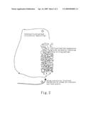
[0014]The management of the fluidised bed material necessitates specific control of the steam circulation in the sense of an air-lift pump motion in order to increase heat and mass exchange and to improve the reaction conditions by increasing the effective reaction space. An air-lift pump is a conveying element in which solid/liquid mixtures are conveyed with the aid of compressed air (driving gas or lift gas) by, e.g. injecting this air by means of nozzles into pipelines or a mixing vessel. The injected gas reduces the suspension density and therefore increases buoyancy. In association with the kinetic energy introduced, this results in conveying.
[0015]A circulation flow is produced as a flow in the vessels, as shown in FIG. 2.
[0016]The fluidised bed is therefore transferred to a solid/gaseous suspension. This principle is transferred in this case to the solid/gaseous suspension of the fluidised bed of the steam converter.
SUMMARY OF THE INVENTION
[0017]The aim of the invention is to provide a method and a device for optimising fluidised bed gasification.
[0018]This problem is solved by an invention having the features of the independent claims.
[0019]No other known method is capable of producing a high-quality synthesis gas at unrivalled low cost, as a result of comparatively low investment costs, with CO2 reduction, or of utilising it as energy and simultaneously processing it into fuel, after appropriate cooling and purification.
[0020]In this invention, the biomass is also gasified in a fluidised bed with steam as an oxidising and fluidising medium, although in this case it is a stationary fluidised bed with two specially developed pulse heaters allowing for the indirect introduction of heat into the fluidised bed situated in the reactor.
[0021]The advantage over fixed bed gasifiers and circulating fluidised beds is the absence of distinct temperature and reaction zones. The fluidised bed consists of an inner bed material. This thus ensures that the individual partial reactions take place simultaneously, as well as a uniform temperature (approximately 800° C.). The method is almost pressureless (up to a maximum of 0.5 bar) and can therefore be carried out in a problem-free manner from a technical point of view. It is characterised by high cost-effectiveness. The initial costs are lower than those of the aforesaid types of gasifier.
[0022]The starting point for further utilisation as a fuel is the medium-calorific gas from the bio-synthesis gas plant (on the basis of renewable raw materials), which, after removing dust and washing out condensable hydrocarbons (oil quenching), can be compressed to approximately 20 bar by means of a turbocompressor and refined by the following process steps: [0023]gas purification and CO2 removal by means of a rectisol plant [0024]optimisation of the H2 to CO ratio by means of the shift method [0025]Fischer-Tropsch synthesis [0026]discharge to a preferred hydrocracker/production diesel with a very high cetane number.
[0027]It can consequently be stated that the method according to the invention is capable of producing 23 t high-quality fuel from 100 t biomass on the basis of the synthesis gas.
[0028]The method according to the invention is characterised in that the motion of the fluidised bed can be controlled in a specific manner by means of jet nozzles. The macroflow that can be obtained for the fluidised bed in this manner, similar to the air-lift pump principle, serves to increase the reaction zone for flash pyrolysis and to increase the retention time of the primary pyrolysis coke in order to increase heat and mass transfer.
[0029]These measures result in an increase in the effective reaction zones in order to increase the space-time yield and to intensify the heterogeneous steam cracking relevant to these secondary reactions.
[0030]The voluminous biomass introduced into the lower part of the steam converter is accelerated by the circulating fluidised bed so that the reaction section and therefore the effective reactor volume for the primary conversion for this reaction are increased by the factor of 2 to 4.
[0031]The feed nozzle furthermore optimises the increase in the yield of CO and H2 as primary products of the steam conversion, with a simultaneous reduction in the yield of methane and higher hydrocarbons.
[0032]Cold gas efficiency is increased by varying the ratio of steam to feed, standing for the thermodynamic efficiency of the steam conversion.
[0033]The aim of the use of one or more steam jet conveyors is to minimise the quantity of steam required for fluidisation and to replace part of the steam with recycled synthesis gas or to increase the introduction of heat by material heat conduction from the region of the pulse heaters.
[0034]The unpurified synthesis gas is enriched with carbon-containing fine dust, due to the technology used. This dust is separated off in a multi-stage purification system consisting of cyclone, multi-cyclone and fine filters.
[0035]The SPOT method is characterised in that this dust is conveyed back to the fluidised bed gravimetrically or by means of a driving jet nozzle. The optimum ratio between the bed material and the fine dust and the high temperature, together with the high reactivity of the recycled fine dust in a heterogeneous steam reaction, result in the coke reacting with steam to form CO and H2.
[0036]It is essential in this connection that the fine dust can be conveyed into the dense fluidised bed with the aid of the driving jet principle, this improving the required effect as a result of an increase in the retention time and intensive mixing of the dust with the hot bed material.
DESCRIPTION OF THE FIGURES
[0037]The figures serve to describe the course of the method and the device in order to provide a clearer understanding of the following detailed description of the preferred embodiment.
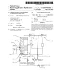
[0038]FIG. 1 shows the steam conversion in the fluidised bed with motion by means of steam jet conveyor and feed nozzle.
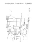
[0039]FIG. 2 shows the steam conversion with fluidised bed motion by means of steam jet conveyors and feed nozzles.
PREFERRED EMBODIMENT
[0040]FIG. 1 shows a gasifier 11 with pulse heaters 12 arranged in the central region of the gasifier 11 in order to form a preferably stationary fluidised bed in this region. The number of pulse heaters can be varied. Both one and two or more are conceivable.
[0041]Steam is introduced into the gasifier as an oxidising and fluidising medium 13. Other fluidising media, such as synthesis gas or CO2, are also conceivable. Feed 14 is furthermore introduced in the region of the pulse heaters 12. This feed can be biomass and other substances, such as lignite or secondary raw materials (such as municipal solid waste, sewage sludge, waste from the food industry, etc.). The biomass is gasified in the fluidised bed consisting of inner bed material at a temperature in the region of approximately 800° C.
[0042]The pulse heaters are operated at Q(pt). Q(pt) means heat flow and refers to the reaction enthalpy (i.e. the calorific value) of the fuel gas used. In addition to the synthesis gas produced in the reformer (product gas), many different fuel gas streams (from propane to natural gas and similar gases) can also be used as the fuel gas, as a result of which, particularly in a combined plant, this pulse heater can be used for the combustion of what are referred to as off-gases produced, so to speak, as by-products during synthesis, such as methanol synthesis, and therefore helps to increase the efficiency of an entire plant.
[0043]This fuel gas is produced as a branch of the natural production during normal operation, i.e. refining the biomass to form a new product: heating gas.
[0044]In a further step, chlorine, present in the form of the chlorine radical and generally originating from organic chlorine compounds, is absorbed or removed by means of further additives. These further additives are preferably calcium hydroxide or the like. These additives are preferably injected into the dust separator 19, 18 or multi-cyclone. It is of course also conceivable for them to be injected directly into the reactor or added to the feed.
[0045]The dust content is separated off in a further step. Various filters and separators 18, 19 are connected in series. Their residues are once again recycled to the reactor. Recycling can be effected at various points, i.e. below the pulse heaters 4 or into the fluidised bed or above the pulse heaters 5 or above the fluidised bed. Cyclones and multi-cyclones, as well as filters, in particular, fine filters, which can be designed as a downstream battery of sintered metal filters, are preferably used. In a first step, one cyclone is arranged downstream, wherein recycling can be effected below or above the pulse heaters by means of a dust separator 18.
[0046]Intermediate cooling to temperatures of between 150 and 700° C. (above the dew point of the synthesis gas) is then preferably effected in a cooler, to be followed by purification in a multi-cyclone in the cooled state.
[0047]The additives calcium hydroxide or the like can be added both to the cyclone and to the multi-cyclone.
[0048]The synthesis gas is then fed to a row of fine filters arranged in parallel or in series.
[0049]The residues from the fine filters and the multi-cyclone are collected in a dust separator 18, 19 and fed back to the reactor at various points, as already described hereinabove. The dust separated off can thus be added above or below the pulse heaters. The dust can also be injected by means of a feed nozzle.
[0050]Parts of the purified or partially purified synthesis gas are returned to the fluidised bed. A steam jet conveyor 3 which introduces the synthesis gas into the steam is preferably used in this connection. It will be clear from FIG. 1 that the synthesis gas is recycled downstream of the first dust separator, as a result of which it is still in this case a synthesis gas enriched with fine dust residues.
[0051]A feed nozzle 15 controlled by a control unit 20 is furthermore used to inject the steam and keep the fluidised bed in motion.
[0052]Another valve 17 serves for the steam supply, thereby bypassing the steam jet conveyor. The supply of superheated steam is determined by the control unit 21.
[0053]FIG. 2 shows a fluidised bed motion 1 controlled by means of feed nozzles and the feed nozzle with the supply of the driving medium.
[0054]Conveying is effected by means of the driving medium as a result of the fluidised bed suspension with low density.
[0055]The description of the embodiments serves only for a clearer understanding thereof and is not intended to be restrictive. The scope of protection of the invention is determined by the claims.
LEGEND
[0056]1 feed nozzle and controlled fluidised bed motion [0057]2 feed nozzle [0058]3 steam jet pump/steam jet conveyor [0059]4 dust feed into the bed "at the bottom" [0060]5 dust feed above fluidised bed [0061]11 reactor, gasifier [0062]12 pulse heater [0063]13 fluidising medium [0064]14 feed [0065]15 feed nozzle for steam supply [0066]16 Q(pt) [0067]17 steam supply bypassing the steam jet conveyor [0068]18 dust separator [0069]19 dust separator [0070]20 control unit for the feed nozzle [0071]21 control unit for the supply of superheated steam
Claims:
1. Method for the gasification of feed to form synthesis gas, with a
gasifier comprising at least one pulse heater, and with a fluidised bed
in the gasifier, in which the fluidised bed is kept in motion in a
controlled manner by means of a feed nozzle introducing steam or
synthesis gas or fine dust into the reactor such that the reaction zone
is increased.
2. The method according to claim 1, in which the feed nozzle is arranged below the fluidised bed.
3. The method according to claim 2, in which the motion of the fluidised bed is controlled in a specific manner by means of jet nozzles.
4. The method according to claim 3, in which the macroflow to be obtained for the fluidised bed is supposed to be similar to the air-lift pump principle, thereby resulting in an increase in the reaction zone for flash pyrolysis and an increase in the retention time of the primary pyrolysis coke in order to increase heat and mass transfer.
5. The method according to claim 1, in which the circulating fluidised bed is controlled in such a manner that the voluminous biomass introduced into the lower part of the steam converter is accelerated so that the reaction section and therefore the effective reactor volume for the primary conversion for this reaction are increased preferably by the factor of 2 to 4.
6. The method according to claim 1, in which the fine dust is conveyed into the dense fluidised bed with the aid of the driving jet principle, the reaction thus being improved as a result of an increase in the retention time and intensive mixing of the dust with the hot bed material.
7. Method for the gasification of feed to form synthesis gas, with a gasifier comprising at least one pulse heater, and with a fluidised bed in the gasifier, comprising:returning parts of the synthesis into the fluidised bed.
8. The method according to claim 7, in which the synthesis gas is fed to the gasifier together with steam.
9. The method according to claim 8, in which at least one steam jet conveyor is used to introduce the synthesis gas into the steam.
10. The method according to claim 9, in which the use of one or more steam jet conveyors is controlled in such a manner that the quantity of steam required for fluidisation is minimised, part of the steam being replaced by recycled synthesis gas and/or the introduction of heat being increased by material heat conduction from the region of the pulse heaters.
11. The method according to claim 7, in which the synthesis gas is recycled in an only partially purified state.
12. A device for the gasification of feed to form synthesis gas, with a gasifier comprising at least one pulse heater, and with a fluidised bed in the gasifier, comprising:a feed nozzle introducing steam or synthesis gas or fine dust into the reactor and controlled by means in such a manner that the fluidised bed is kept in motion so that the reaction zone is increased.
13. The device according to claim 12, in which the feed nozzle is arranged below the fluidised bed.
14. The device according to claim 13, in which the feed nozzles are jet nozzles which control the motion of the fluidised bed in a specific manner.
15. The device according to claim 14, in which the control means are designed in such a manner that the macroflow to be obtained for the fluidised bed is similar to the air-lift pump principle, thereby resulting in an increase in the reaction zone for flash pyrolysis and an increase in the retention time of the primary pyrolysis coke in order to increase heat and mass transfer.
16. The device according to claim 12, in which the control unit for the feed nozzles is designed in such a manner that the circulating fluidised bed is controlled in such a manner that the voluminous biomass introduced into the lower part of the steam converter is accelerated so that the reaction section and therefore the effective reactor volume for the primary conversion for this reaction are increased preferably by the factor of 2 to 4.
17. The device according to claim 12, in which the feed nozzles inject fine dust from the synthesis gas purification process into the dense fluidised bed, the reaction thus being improved as a result of an increase in the retention time and intensive mixing of the dust with the hot bed material.
18. A device for the gasification of feed to form synthesis gas, with a gasifier comprising at least one pulse heater, and with a fluidised bed in the gasifier, in which means are provided for returning parts of the synthesis gas to the fluidised bed.
19. The device according to claim 18, in which means are provided for feeding the synthesis gas to the gasifier together with the steam.
20. The device according to claim 19, in which at least one steam jet conveyor is provided to introduce the synthesis gas into the steam.
21. The device according to claim 20, in which means are provided to control the use of one or more steam jet conveyors in such a manner that the quantity of steam required for fluidisation is minimised, part of the steam being replaced by recycled synthesis gas and/or the introduction of heat being increased by material heat conduction from the region of the pulse heaters.
22. The device according to claim 18, in which means are provided for recycling the synthesis gas in an only partially purified state.
Description:
[0001]This application in a continuation of PCT/EP2007/052259 filed Mar.
9, 2007, which claims priority to DE 10 2006 019 999.5 filed Apr. 26,
2006 and DE 10 2006 022 265.2 filed May 11, 2006, all of which are
incorporated by reference.
FIELD OF THE INVENTION
[0002]The development of thermal gasification methods has produced essentially three different types of gasifier, namely entrained bed gasifiers, fixed bed gasifiers and fluidised bed gasifiers.
[0003]Primarily fixed bed gasifiers and fluidised bed gasifiers have been developed further for commercial gasification.
[0004]Of the many different technical approaches in the field of fixed bed gasification, the Carbo V method will be described by way of example here.
[0005]Relevant literature for fluidised bed gasification, which forms part of this application, is as follows: "High-Temperature Winkler Gasification of Municipal Solid Waste"; Wolfgang Adlhoch, Rheinbraun A G, Hisaaki Sumitomo Heavy Industries, Ltd., Joachim Wolff, Karsten Radtke (Speaker), Krupp Uhde GmbH; Gasification Technology Conference; San Francisco, Calif., USA; Oct. 8-11, 2000; Conference Proceedings.
[0006]Relevant literature for circulating fluidised beds in a combined system, which forms part of this application, is as follows: "Dezentrale Strom-und Warmeerzeugung auf Basis Biomasse-Vergasung"; R. Rauch, H. Hofbauer; Lecture, Uni Leipzig 2004. "Zirkulierende Wirbelschicht, Vergasung mit Luft, Operation Experience with CfB--Technology for Waste, Utilisation at a Cement Production Plant" R. Wirthwein, P. Scur, K.-F. Scharf--Rudersdorfer Zement GmbH, H. Hirschfelder--Lurgi Energie und Entsorgungs GmbH; 7th International Conference on Circulating Fluidized Bed Technologies; Niagara Falls, May 2002.
[0007]Relevant literature for combined fixed beds (rotary tube), which forms part of this application, is as follows: 30 MV Carbo V Biomass Gasifier for Municipal CHP; The CHP Project for the City of Aachen, Matthias Rudloff, Lecture, Paris, October 2005.
[0008]Relevant literature for combined systems for fixed bed gasification (slag tap gasifier), which forms part of this application, is as follows: Operation Results of the BGL Gasifier at Schwarze Pumpe, Dr. Hans-Joachim Sander S V Z, Dr. Georg Daradimos, Hansjobst Hirschfelder, Envirotherm; Gasification Technologies 2003; San Francisco, Calif., Oct. 12-15, 2003; Conference Proceedings.
[0009]In the Carbo V method, gasification takes place in two stages. The biomass is first split into its volatile and solid constituents at 500° C. A tarry gas and additionally "wood charcoal" are produced. The gas is burnt at temperatures in excess of 1200° C., the tars breaking down to CO2 and H2. A product gas containing CO and H2 is then produced with the hot flue gas and the wood charcoal.
[0010]As a result of the high technical complexity and the high costs due to the high pressure level (up to 40 bar), gasifiers of these types are completely unsuitable for the gasification of biomass (which occurs regionally and has a significant influence on the costs for logistics and processing).
[0011]Fluidised bed gasifiers can be divided into two methods differing from one another by the heating of the fluidised bed, namely circulating fluidised bed gasifiers and stationary fluidised bed gasifiers.
[0012]Relevant literature for desulphurisation in fluidised bed gasification, which forms part of this application, is as follows: Gasification of Lignite and Wood in the Lurgi Circulating Fluidized Bed Gasifier; Research Project 2656-3: Final Report, August 1988, P. Mehrling, H. Vierrath; LURGI GmbH; for Electric Power Research Institute, Palo Alto, Calif.: ZWS-Druckvergasung im Kombiblock, Final Report BMFT FB 03 E 6384-A; P. Mehrling, LURGI GmbH; Bewag.
[0013]An allothermal circulating fluidised bed gasification plant was put into operation in Gussing (Austria) at the beginning of 2002. The biomass is gasified in a fluidised bed with steam as an oxidising agent. In order to provide the heat for the gasification process, part of the wood charcoal produced in the fluidised bed is burnt in a second fluidised bed. The gasification under steam produces a product gas. The high initial costs for the plant technology and excessive process control costs have a disadvantageous effect.
[0014]The management of the fluidised bed material necessitates specific control of the steam circulation in the sense of an air-lift pump motion in order to increase heat and mass exchange and to improve the reaction conditions by increasing the effective reaction space. An air-lift pump is a conveying element in which solid/liquid mixtures are conveyed with the aid of compressed air (driving gas or lift gas) by, e.g. injecting this air by means of nozzles into pipelines or a mixing vessel. The injected gas reduces the suspension density and therefore increases buoyancy. In association with the kinetic energy introduced, this results in conveying.
[0015]A circulation flow is produced as a flow in the vessels, as shown in FIG. 2.
[0016]The fluidised bed is therefore transferred to a solid/gaseous suspension. This principle is transferred in this case to the solid/gaseous suspension of the fluidised bed of the steam converter.
SUMMARY OF THE INVENTION
[0017]The aim of the invention is to provide a method and a device for optimising fluidised bed gasification.
[0018]This problem is solved by an invention having the features of the independent claims.
[0019]No other known method is capable of producing a high-quality synthesis gas at unrivalled low cost, as a result of comparatively low investment costs, with CO2 reduction, or of utilising it as energy and simultaneously processing it into fuel, after appropriate cooling and purification.
[0020]In this invention, the biomass is also gasified in a fluidised bed with steam as an oxidising and fluidising medium, although in this case it is a stationary fluidised bed with two specially developed pulse heaters allowing for the indirect introduction of heat into the fluidised bed situated in the reactor.
[0021]The advantage over fixed bed gasifiers and circulating fluidised beds is the absence of distinct temperature and reaction zones. The fluidised bed consists of an inner bed material. This thus ensures that the individual partial reactions take place simultaneously, as well as a uniform temperature (approximately 800° C.). The method is almost pressureless (up to a maximum of 0.5 bar) and can therefore be carried out in a problem-free manner from a technical point of view. It is characterised by high cost-effectiveness. The initial costs are lower than those of the aforesaid types of gasifier.
[0022]The starting point for further utilisation as a fuel is the medium-calorific gas from the bio-synthesis gas plant (on the basis of renewable raw materials), which, after removing dust and washing out condensable hydrocarbons (oil quenching), can be compressed to approximately 20 bar by means of a turbocompressor and refined by the following process steps: [0023]gas purification and CO2 removal by means of a rectisol plant [0024]optimisation of the H2 to CO ratio by means of the shift method [0025]Fischer-Tropsch synthesis [0026]discharge to a preferred hydrocracker/production diesel with a very high cetane number.
[0027]It can consequently be stated that the method according to the invention is capable of producing 23 t high-quality fuel from 100 t biomass on the basis of the synthesis gas.
[0028]The method according to the invention is characterised in that the motion of the fluidised bed can be controlled in a specific manner by means of jet nozzles. The macroflow that can be obtained for the fluidised bed in this manner, similar to the air-lift pump principle, serves to increase the reaction zone for flash pyrolysis and to increase the retention time of the primary pyrolysis coke in order to increase heat and mass transfer.
[0029]These measures result in an increase in the effective reaction zones in order to increase the space-time yield and to intensify the heterogeneous steam cracking relevant to these secondary reactions.
[0030]The voluminous biomass introduced into the lower part of the steam converter is accelerated by the circulating fluidised bed so that the reaction section and therefore the effective reactor volume for the primary conversion for this reaction are increased by the factor of 2 to 4.
[0031]The feed nozzle furthermore optimises the increase in the yield of CO and H2 as primary products of the steam conversion, with a simultaneous reduction in the yield of methane and higher hydrocarbons.
[0032]Cold gas efficiency is increased by varying the ratio of steam to feed, standing for the thermodynamic efficiency of the steam conversion.
[0033]The aim of the use of one or more steam jet conveyors is to minimise the quantity of steam required for fluidisation and to replace part of the steam with recycled synthesis gas or to increase the introduction of heat by material heat conduction from the region of the pulse heaters.
[0034]The unpurified synthesis gas is enriched with carbon-containing fine dust, due to the technology used. This dust is separated off in a multi-stage purification system consisting of cyclone, multi-cyclone and fine filters.
[0035]The SPOT method is characterised in that this dust is conveyed back to the fluidised bed gravimetrically or by means of a driving jet nozzle. The optimum ratio between the bed material and the fine dust and the high temperature, together with the high reactivity of the recycled fine dust in a heterogeneous steam reaction, result in the coke reacting with steam to form CO and H2.
[0036]It is essential in this connection that the fine dust can be conveyed into the dense fluidised bed with the aid of the driving jet principle, this improving the required effect as a result of an increase in the retention time and intensive mixing of the dust with the hot bed material.
DESCRIPTION OF THE FIGURES
[0037]The figures serve to describe the course of the method and the device in order to provide a clearer understanding of the following detailed description of the preferred embodiment.
[0038]FIG. 1 shows the steam conversion in the fluidised bed with motion by means of steam jet conveyor and feed nozzle.
[0039]FIG. 2 shows the steam conversion with fluidised bed motion by means of steam jet conveyors and feed nozzles.
PREFERRED EMBODIMENT
[0040]FIG. 1 shows a gasifier 11 with pulse heaters 12 arranged in the central region of the gasifier 11 in order to form a preferably stationary fluidised bed in this region. The number of pulse heaters can be varied. Both one and two or more are conceivable.
[0041]Steam is introduced into the gasifier as an oxidising and fluidising medium 13. Other fluidising media, such as synthesis gas or CO2, are also conceivable. Feed 14 is furthermore introduced in the region of the pulse heaters 12. This feed can be biomass and other substances, such as lignite or secondary raw materials (such as municipal solid waste, sewage sludge, waste from the food industry, etc.). The biomass is gasified in the fluidised bed consisting of inner bed material at a temperature in the region of approximately 800° C.
[0042]The pulse heaters are operated at Q(pt). Q(pt) means heat flow and refers to the reaction enthalpy (i.e. the calorific value) of the fuel gas used. In addition to the synthesis gas produced in the reformer (product gas), many different fuel gas streams (from propane to natural gas and similar gases) can also be used as the fuel gas, as a result of which, particularly in a combined plant, this pulse heater can be used for the combustion of what are referred to as off-gases produced, so to speak, as by-products during synthesis, such as methanol synthesis, and therefore helps to increase the efficiency of an entire plant.
[0043]This fuel gas is produced as a branch of the natural production during normal operation, i.e. refining the biomass to form a new product: heating gas.
[0044]In a further step, chlorine, present in the form of the chlorine radical and generally originating from organic chlorine compounds, is absorbed or removed by means of further additives. These further additives are preferably calcium hydroxide or the like. These additives are preferably injected into the dust separator 19, 18 or multi-cyclone. It is of course also conceivable for them to be injected directly into the reactor or added to the feed.
[0045]The dust content is separated off in a further step. Various filters and separators 18, 19 are connected in series. Their residues are once again recycled to the reactor. Recycling can be effected at various points, i.e. below the pulse heaters 4 or into the fluidised bed or above the pulse heaters 5 or above the fluidised bed. Cyclones and multi-cyclones, as well as filters, in particular, fine filters, which can be designed as a downstream battery of sintered metal filters, are preferably used. In a first step, one cyclone is arranged downstream, wherein recycling can be effected below or above the pulse heaters by means of a dust separator 18.
[0046]Intermediate cooling to temperatures of between 150 and 700° C. (above the dew point of the synthesis gas) is then preferably effected in a cooler, to be followed by purification in a multi-cyclone in the cooled state.
[0047]The additives calcium hydroxide or the like can be added both to the cyclone and to the multi-cyclone.
[0048]The synthesis gas is then fed to a row of fine filters arranged in parallel or in series.
[0049]The residues from the fine filters and the multi-cyclone are collected in a dust separator 18, 19 and fed back to the reactor at various points, as already described hereinabove. The dust separated off can thus be added above or below the pulse heaters. The dust can also be injected by means of a feed nozzle.
[0050]Parts of the purified or partially purified synthesis gas are returned to the fluidised bed. A steam jet conveyor 3 which introduces the synthesis gas into the steam is preferably used in this connection. It will be clear from FIG. 1 that the synthesis gas is recycled downstream of the first dust separator, as a result of which it is still in this case a synthesis gas enriched with fine dust residues.
[0051]A feed nozzle 15 controlled by a control unit 20 is furthermore used to inject the steam and keep the fluidised bed in motion.
[0052]Another valve 17 serves for the steam supply, thereby bypassing the steam jet conveyor. The supply of superheated steam is determined by the control unit 21.
[0053]FIG. 2 shows a fluidised bed motion 1 controlled by means of feed nozzles and the feed nozzle with the supply of the driving medium.
[0054]Conveying is effected by means of the driving medium as a result of the fluidised bed suspension with low density.
[0055]The description of the embodiments serves only for a clearer understanding thereof and is not intended to be restrictive. The scope of protection of the invention is determined by the claims.
LEGEND
[0056]1 feed nozzle and controlled fluidised bed motion [0057]2 feed nozzle [0058]3 steam jet pump/steam jet conveyor [0059]4 dust feed into the bed "at the bottom" [0060]5 dust feed above fluidised bed [0061]11 reactor, gasifier [0062]12 pulse heater [0063]13 fluidising medium [0064]14 feed [0065]15 feed nozzle for steam supply [0066]16 Q(pt) [0067]17 steam supply bypassing the steam jet conveyor [0068]18 dust separator [0069]19 dust separator [0070]20 control unit for the feed nozzle [0071]21 control unit for the supply of superheated steam
User Contributions:
Comment about this patent or add new information about this topic:
| People who visited this patent also read: | |
| Patent application number | Title |
|---|---|
| 20120189592 | METHODS FOR PROMOTING HEMATOPOIETIC RECONSTITUTION |
| 20120189591 | COMPOSITIONS AND IMPROVED SOFT TISSUE REPLACEMENT METHODS |
| 20120189590 | COMPOSITIONS AND IMPROVED SOFT TISSUE REPLACEMENT METHODS |
| 20120189589 | COMPOSITIONS AND IMPROVED SOFT TISSUE REPLACEMENT METHODS |
| 20120189588 | Compositions and Methods for Implantation of Processed Adipose Tissue and Processed Adipose Tissue Products |
Images included with this patent application:
 |  |
 |
| Similar patent applications: | |
| Date | Title |
|---|---|
| 2013-01-24 | Method and an apparatus for sweetening and dehydrating a hydrocarbon gas, in particular a natural gas |
| 2009-03-12 | Method and reactor for biomass pyrolytic conversion |
| 2010-02-25 | Methods and systems for partial moderator bypass |
| 2010-05-13 | Multiple fixed-fluidized beds for contaminant removal |
| 2008-10-09 | Fluid mixing device inserted in or combined with a reactor |
| New patent applications in this class: | |
| Date | Title |
|---|---|
| 2016-03-24 | Gasifier for solid carbon fuel |
| 2016-02-18 | Waste to fuel system |
| 2013-08-08 | Solar gasifier |
| 2013-02-14 | Decentralized hydrocarbon refining and distribution |
| 2011-12-01 | Meltable fuel gas generation apparatus and methods |
| New patent applications from these inventors: | |
| Date | Title |
|---|---|
| 2011-06-09 | Method and device for producing energy, dme (dimethyl ether) and bio-silica using co2-neutral biogenic reactive and inert ingredients |
| 2009-07-09 | Feed system |
| 2009-03-05 | Method and device for the process-integrated hot gas purification of dust and gas components of a synthesis gas |
| Top Inventors for class "Gas: heating and illuminating" | |
| Rank | Inventor's name |
|---|---|
| 1 | Earl T. Robinson |
| 2 | Toshiyuki Suda |
| 3 | James A. Batdorf |
| 4 | Jeffrey E Surma |
| 5 | Manfred Schingnitz |