Patent application title: WATER TRAP WITH AN EMPTYING DEVICE
Inventors:
Thomas Maxeiner (Lubeck, DE)
Gerd Peter (Lubeck, DE)
Assignees:
Drager Medical AG & Co. KG
IPC8 Class: AA61M1600FI
USPC Class:
12820512
Class name: Respiratory method or device means for supplying respiratory gas under positive pressure means for removing substance from respiratory gas
Publication date: 2009-04-02
Patent application number: 20090084383
Inventors list |
Agents list |
Assignees list |
List by place |
Classification tree browser |
Top 100 Inventors |
Top 100 Agents |
Top 100 Assignees |
Usenet FAQ Index |
Documents |
Other FAQs |
Patent application title: WATER TRAP WITH AN EMPTYING DEVICE
Inventors:
Thomas MAXEINER
Gerd PETER
Agents:
MCGLEW & TUTTLE, PC
Assignees:
DRAGER MEDICAL AG & CO. KG
Origin: SCARBOROUGH, NY US
IPC8 Class: AA61M1600FI
USPC Class:
12820512
Abstract:
A breathing gas system and water trap (1) is improved in respect to the
reliability of operation and has an emptying device. The water trap (1)
has a gas inlet (4), which meets a first water separating membrane (5)
via a connection line. The connection line leads into a water tank (20)
located deeper in the incoming flow direction from the first water
separating membrane (5) and into a gas measuring device (2) with vacuum
on the discharge side from the first water separating membrane (5) from
the water trap (1). The water tank (20) has a rinsing gas flow line,
which is arranged above the liquid level, leads upward via a
gas-permeable membrane (6) and is likewise connected to the applied
vacuum of the gas measuring device (2). The water tank (20) has a water
transport line for emptying the water tank (20), which water transport
line extends into the liquid and is provided with a downstream vacuum via
a nonreturn valve (7) and a downstream liquid pump (17) or via a solenoid
valve (21). The water trap (1) is equipped with a filling level detection
system (8, 9, 22; 8, 9, 13; 8, 10), which is connected to a control and
analyzing unit (3). The control and analyzing unit (3) is connected to
the liquid pump (17) or to the solenoid valve (21), so that the water
tank (20) can be emptied as a function of the signal of the filling level
detection system (8, 9, 22; 8, 9, 13; 8, 10).Claims:
1. A water trap connected to a gas measuring device, the water trap
comprising:a gas inlet;a connection line;a first water separation
membrane, said gas inlet leading to said first water separation membrane
via said connection line;a water tank, said connection line leading from
said first water separation membrane into said water tank on an incoming
flow side of said water separation membrane, and leading to the gas
measuring device on an outflow side of said water separation membrane and
with a vacuum of the gas measuring device applied thereto;a gas-permeable
membrane, said water tank having a rinsing gas flow line arranged above a
liquid level and leading upward via said gas-permeable membrane to the
gas measuring device and with the vacuum of the gas measuring device
applied thereto;a water transport line associated with said water tank
and extending below the liquid level of said water tank for the emptying
said water tank;one of a nonreturn valve with downstream liquid pump for
providing a downstream suction in said water transport line and a
solenoid valve with downstream vacuum in said water transport line;a
control and analyzing unit; anda filling level detection system connected
to said control and analyzing unit, said control and analyzing unit being
connected to said liquid pump or to said solenoid valve so that said
water tank can be emptied as a function of a signal of said filling level
detection system.
2. A water trap in accordance with claim 1, wherein:said filling level detection system has a detector unit;said filling level detection system has at least one of a RFID tag arranged on an outer side of said water tank and a transponder comprising a float element for detecting a change in liquid level in said water tank by means of said detector unit based on a variable received signal or the field attenuation through the liquid.
3. A water trap in accordance with claim 1, wherein said filling level detection system comprises an optical transmitting and receiving means.
4. A water trap in accordance with claim 1, wherein said solenoid valve is connected to a bronchial suction of an anesthesia apparatus to provide said downstream vacuum.
5. A water trap in accordance with claim 1, further comprising a flow sensor connected to said control and analyzing unit, said flow sensor being arranged in the water transport line for detecting an amount of liquid being delivered.
6. A water trap in accordance with claim 1, wherein said gas measuring means is connected to said control and analyzing unit by a signal transmission provided from the gas measuring device to said control and analyzing unit so that said one of said liquid pump and said solenoid valve are controlled as a function of pressure and/or volume flow signals detected in the gas measuring device at an outlet of the connection line and the rinsing gas flow line.
7. A water trap in accordance with claim 1, wherein said first water separation membrane and said gas-permeable membrane are formed of a hydrophobic gas-permeable material.
8. A water trap in accordance with claim 7, wherein said hydrophobic gas-permeable material is one of Polytetrafluoroethylene (PTFE) or a PTFE copolymer.
9. A breathing gas system with water trap, the system comprising:a medical device breathing gas line;a gas measuring device;a water trap connected to the medical device breathing gas line upstream of the gas measuring device, the water trap comprising a gas inlet receiving breathing gas from the medical device breathing gas line, a connection line, a first water separation membrane, said gas inlet leading to said first water separation membrane via said connection line, a water tank, said connection line leading from said first water separation membrane into said water tank on an incoming flow side of said water separation membrane, and leading to said gas measuring device on an outflow side of said water separation membrane and with a vacuum of the gas measuring device applied thereto, a gas-permeable membrane, said water tank having a rinsing gas flow line arranged above a liquid level and leading upward via said gas-permeable membrane to said gas measuring device and with the vacuum of the gas measuring device applied thereto, a water transport line associated with said water tank and extending below the liquid level of said water tank for emptying said water tank, one of a nonreturn valve with downstream liquid pump for providing a downstream suction in said water transport line and a solenoid valve with downstream vacuum in said water transport line, a control and analyzing unit, and a filling level detection system connected to said control and analyzing unit, said control and analyzing unit being connected to said liquid pump or to said solenoid valve so that said water tank can be emptied as a function of a signal of said filling level detection system.
10. A breathing gas system in accordance with claim 10, wherein:said filling level detection system has a detector unit;said filling level detection system has at least one of a RFID tag arranged on an outer side of said water tank and a transponder comprising a float element for detecting a change in liquid level in said water tank by means of said detector unit based on a variable received signal or the field attenuation through the liquid.
11. A breathing gas system in accordance with claim 10, wherein said filling level detection system comprises an optical transmitting and receiving means.
12. A breathing gas system in accordance with claim 10, wherein said solenoid valve is connected to a bronchial suction of an anesthesia apparatus to provide said downstream vacuum.
13. A breathing gas system in accordance with claim 10, further comprising a flow sensor connected to said control and analyzing unit, said flow sensor being arranged in the water transport line for detecting an amount of liquid being delivered.
14. A breathing gas system in accordance with claim 10, wherein said gas measuring device is connected to said control and analyzing unit by a signal transmission provided from said gas measuring unit to said control and analyzing unit so that said one of said liquid pump and said solenoid valve are controlled as a function of pressure and/or volume flow signals detected in said gas measuring device at an outlet of the connection line and the rinsing gas flow line.
15. A breathing gas system in accordance with claim 10, wherein said first water separation membrane and said gas-permeable membrane are formed of a hydrophobic gas-permeable material.
16. A breathing gas system in accordance with claim 15, wherein said hydrophobic gas-permeable material is one of Polytetrafluoroethylene (PTFE) or a PTFE copolymer.
Description:
CROSS REFERENCE TO RELATED APPLICATIONS
[0001]This application claims the benefit of priority under 35 U.S.C. §119 of German Patent Application DE 10 2007 046 533.7 filed Sep. 28, 2007, the entire contents of which are incorporated herein by reference.
FIELD OF THE INVENTION
[0002]The present invention pertains to a water trap with an emptying device.
BACKGROUND OF THE INVENTION
[0003]A prior-art water trap for use in a breathing gas line of an anesthesia apparatus or respirator for separating moisture contained in the breathing gas appears, for example, from DE 199 01 590 C1 (corresponding to U.S. application Ser. No. 06/117,214). The breathing gas, from which the moisture has been removed, flows downstream of the water trap especially into an infrared optical measuring unit for the analysis or determination of the concentration of constituents of the breathing gas or gaseous anesthetics contained in the breathing gas. Just like the water trap according to the present invention, the prior-art water trap can be replaceably connected to a holder of an anesthesia apparatus.
[0004]The water traps used so far as described in the area of medical engineering include both water traps for single-time use and water traps for multiple use, the water container for the moisture collected being emptied in the latter case, in general, by the operating staff after a certain operating time by means of a syringe and put out of operation after certain intervals of use. It may happen that the gas measurement will fail if the replacement intervals are not observed.
SUMMARY OF THE INVENTION
[0005]The object of the present invention is to provide a water trap improved in terms of reliability of operation and operation.
[0006]According to the invention, a water trap is provided that is connected to a gas measuring device. The water trap comprises a gas inlet, a connection line, a first water separation membrane, a water tank and a gas-permeable membrane. The gas inlet leads to the first water separation membrane via the connection line. The connection line leads from the first water separation membrane into the water tank on an incoming flow side of the water separation membrane, and leads to the gas measuring device on an outflow side of the water separation membrane and with a vacuum of the gas measuring device applied thereto. The water tank has a rinsing gas flow line arranged above a liquid level and leads upward via the gas-permeable membrane to the gas measuring device and with the vacuum of the gas measuring device applied thereto. A water transport line is associated with the water tank and extends below the liquid level of the water tank for the emptying the water tank. Either a nonreturn valve with a downstream liquid pump for providing a downstream suction in the water transport line or a solenoid valve with downstream vacuum in the water transport line is provided. A filling level detection system is connected to a control and analyzing unit that is connected to the liquid pump or to the solenoid valve so that the water tank can be emptied as a function of a signal of the filling level detection system.
[0007]The filling level detection system may have a detector unit. The filling level detection system may have at least one of a RFID tag arranged on the outer side of the water tank and a transponder designed as a float element for detecting the changed liquid level in the water tank by means of the detector unit based on a variable received signal or the field attenuation through the liquid.
[0008]The filling level detection system may comprise an optical transmitting and receiving means.
[0009]The solenoid valve may be connected to a bronchial suction of an anesthesia apparatus to provide the downstream vacuum.
[0010]A flow sensor may be connected to the control and analyzing unit. Such a flow sensor may be arranged in the water transport line for detecting the amount of liquid being delivered.
[0011]The gas measuring means may be connected to the control and analyzing means by a signal transmission provided from the gas measuring means to the control and analyzing means so that one of the liquid pump and the solenoid valve are controlled as a function of pressure and/or volume flow signals detected in the gas measuring means at an outlet of the connection line and the rinsing gas flow line.
[0012]The water separating membrane and the gas-permeable membrane may be formed of a hydrophobic gas-permeable material. The hydrophobic gas-permeable material may be one of Polytetrafluoroethylene (PTFE) or a PTFE copolymer.
[0013]The various features of novelty which characterize the invention are pointed out with particularity in the claims annexed to and forming a part of this disclosure. For a better understanding of the invention, its operating advantages and specific objects attained by its uses, reference is made to the accompanying drawings and descriptive matter in which preferred embodiments of the invention are illustrated.
BRIEF DESCRIPTION OF THE DRAWINGS
[0014]In the drawings:
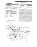
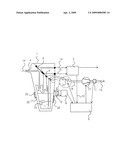
[0015]The only FIGURE is a schematic view showing exemplary embodiments of a water trap with the essential components according to the present invention.
DESCRIPTION OF THE PREFERRED EMBODIMENTS
[0016]Referring to the drawings in particular, the breathing gas 19 to be analyzed flows due to a vacuum applied, for example, as expired breathing gas of a patient connected to an anesthesia apparatus via the water trap 1 into a gas measuring means 2 for determining the concentrations of constituents of the gas. Such a gas measuring means may be, for example, an infrared optical, electrochemical and/or paramagnetic measuring means. The breathing gas 19 first enters the water trap 1 at the gas inlet 4. The gas to be measured enters the gas measuring means 2 in the measured gas flow 14.
[0017]The water entrained in the gas flow is separated at the water separation membrane 5 made of a hydrophobic membrane material, such as Polytetrafluoroethylene (PTFE--also known as Teflon®), and delivered into the water tank 20 by means of a vacuum-operated rinsing gas flow 15 and supported by the force of gravity. The second, likewise water-impermeable, but gas-permeable membrane 6 made of a hydrophobic material prevents water from accidentally entering the connected pneumatic system of the gas measuring means 2 via the rinsing gas flow branch. The separated water collects in the water tank 20 of the water trap 1.
[0018]The water level of the amount of water separated rises in the water tank 20 in the further course of the operation until the water tank is filled, so that emptying of the water tank 20 is necessary in order to make it possible to continue the gas measurement. According to the current state of the art, a water tank such as the water tank 20 is emptied by the operating staff manually, which is prompted either by a failure of the gas measurement, a visual checking of the water level in the preferably transparent water tank 20 or a warning signal of a filling level detection system.
[0019]According to the invention, a filling level detection system is provided based, for example, on: [0020]a) the evaluation of pneumatic parameters in the measured gas and rinsing gas flow branch of the gas measuring means 2, with a signal transmission 12 to the control and analyzing unit 3; or [0021]b) an optical detection 10 of the water level by means of the detector unit 8, optionally by means of a float element 13; or [0022]c) on a filling level detector via the field attenuation of a detector unit 8 for an RFID tag 22, which the detector unit is designed as a transmitting/receiving means.
[0023]The water tank 20 is preferably transparent to the wavelength of light used for the measurement for the optical detection of the filling level.
[0024]The mode of operation of the present automatic emptying device is as follows:
[0025]When the filling level detection system 10, 8 (infrared optical) or 9, 8 (electromagnetic/inductive) responds, a signal is sent to the control and analyzing unit 3. The control and analyzing unit 3 thereupon causes a liquid pump 17 to be switched on. The water is pumped by the liquid pump 17 via the nonreturn valve 7 and the flexible tube 18 to the liquid discharge line 16. Complete emptying of the water tank 20 is ensured, for example, by the on time of the liquid pump 17, the liquid pump 17 being actuated by the control and analyzing unit 3.
[0026]In a special embodiment, the amount of liquid pumped off is determined by flow measurement by means of the flow sensor 11, and the result is sent to the control and analyzing unit 3. Besides the duration of use, an intensity of use can thus also be recorded and updated by means of an additional RFID tag 23 as a criterion of wear and use for each water trap 1.
[0027]In an alternative embodiment, vacuum is generated for drawing off the contents of the water tank 20 by the bronchial suction present in anesthesia apparatuses, which is connected via the solenoid valve 21. The nonreturn valve 7 and the liquid pump 17 are not necessary in this case. The number of valve switchings of the solenoid valve 21 corresponds in this case to the number of emptying operations and can be used as a parameter of wear corresponding to the intensity of use.
[0028]The reading and/or data recording of the additional RFID tag 23 is carried out either by means of another contactless transmitting/receiving means, not shown, of the anesthesia apparatus, or it can be carried out, as an alternative, especially by means of the detector unit 8 already present for the RFID tag 22.
[0029]While specific embodiments of the invention have been shown and described in detail to illustrate the application of the principles of the invention, it will be understood that the invention may be embodied otherwise without departing from such principles.
User Contributions:
comments("1"); ?> comment_form("1"); ?>Inventors list |
Agents list |
Assignees list |
List by place |
Classification tree browser |
Top 100 Inventors |
Top 100 Agents |
Top 100 Assignees |
Usenet FAQ Index |
Documents |
Other FAQs |
User Contributions:
Comment about this patent or add new information about this topic:
Images included with this patent application:
 |  |
| Similar patent applications: | |
| Date | Title |
|---|---|
| 2012-06-28 | Adaptable oxygen regulator system and method with an electronic control device |
| 2009-05-28 | Water-sealing diving-use snorkel without generating a vacuum suction force |
| 2008-11-13 | Re-breather apparatus with vaned filtering canister |
| 2012-05-31 | Methods and systems for saliva management with an oral device |
| 2009-05-14 | Controller for an extremity hyperbaric device |
| New patent applications in this class: | |
| Date | Title |
|---|---|
| 2018-01-25 | Coal miner personal air filtration system specially adapted for low ceiling mines |
| 2016-04-28 | Flow diffuser and sound cone |
| 2016-02-11 | Oxygen face mask and component system |
| 2016-01-21 | Rebreather system and components |
| 2016-01-21 | Positive airway pressure systems |
| New patent applications from these inventors: | |
| Date | Title |
|---|---|
| 2021-11-04 | Process and device for detection of a leak in a ventilation circuit |
| 2014-10-30 | Device for removal of gas from a respiratory circuit |
| 2011-02-10 | Anesthesia system |
| 2010-12-09 | Water trap |
| Top Inventors for class "Surgery" | |
| Rank | Inventor's name |
|---|---|
| 1 | Peter Chi Fai Ho |
| 2 | Philip Rodney Kwok |
| 3 | Per Gisle Djupesland |
| 4 | Alastair Edwin Mcauley |
| 5 | Roderick A. Hyde |