Patent application title: System and method for integrated stage separation
Inventors:
Thomas G. Lee (Oro Valley, AZ, US)
Shek M. Cheung (Tucson, AZ, US)
Gregory E. Longerich (Oro Valley, AZ, US)
IPC8 Class: AF42B1536FI
USPC Class:
102377
Class name: Ammunition and explosives having reaction motor having separation means
Publication date: 2009-03-26
Patent application number: 20090078145
aration system and method that facilitates an
active separation on the booster by igniting a small quantity of
propellant in the dead volume between the second stage rocket motor
nozzle and the booster dome. In the most general embodiment, the
invention includes a nozzle; a first fuel propellant disposed within the
nozzle; a thermal barrier separating the first and second fuel
propellant, an environmental seal protecting the second fuel propellant
and an arrangement for activating the first fuel propellant. The nozzle
is disposed in an upper stage of a two-stage vehicle. An arrangement such
as a V-Band clamp is included for retaining the lower stage of the
two-stage vehicle. Electronic commands release the lower stage and
activate the first propellant in a timely manner to effectively separate
the lower stage from the upper stage. The embedded propellant is
activated with an arm fire device.Claims:
1. A vehicle separation system for use in a multi-stage vehicle having a
first stage and a second stage, said system comprising:a nozzle disposed
in said second stage of said vehicle, said nozzle being designed to burn
fuel propellant;fuel propellant embedded within said nozzle; andmeans for
activating said fuel propellant to separate said first stage from said
second stage and expel said first stage from said vehicle,whereupon on
ignition of said second stage, said second stage is propelled.
2-4. (canceled)
5. The invention of claim 1 further including means for retaining said first stage of said vehicle.
6. The invention of claim 5 wherein said means for retaining includes a V-Band clamp.
7-20. (canceled)
21. A multi-stage vehicle comprising:a first lower stage;a second upper stage;a nozzle disposed in said second stage, said nozzle being designed to burn fuel propellant; anda fuel propellant embedded in said nozzle; andmeans for selectively activating said fuel propellant in said nozzle to separate said first lower stage from said second upper stage.
22. A method for effecting separation of a multi-stage vehicle having a first lower stage and a second upper stage and a nozzle disposed in said second stage of said vehicle including the steps of:embedding a fuel propellant within said nozzle in said upper stage of said vehicle andactivating said propellant to separate said first stage from said second stage and expel said first stage from said vehicle,whereupon on ignition of said second stage, said second stage is propelled.Description:
BACKGROUND OF THE INVENTION
[0001]1. Field of the Invention
[0002]The present invention relates to aeronautics, astronautics and hydraulics. More specifically, the present invention relates to systems and methods for effecting separation between stages of multi-stage vehicles.
[0003]2. Description of the Related Art
[0004]Multi-stage vehicles are used in a variety of applications including space, aerospace, and hydrospace applications. Separation is typically achieved by either an active or a passive approach. Active approaches include the use of retrorockets, explosives and/or mechanical arrangements (springs or other devices for storing energy). Passive approaches include arrangements for using drag to effect stage separation.
[0005]Unfortunately, the active approaches are typically somewhat complex, more costly and require considerably more space that passive approaches. Passive approaches, on the other hand, are beset by poor performance in designs where the upper stage has a diameter that is equal to or greater than that of the separating (lower) stage.
[0006]Hence, a need remains in the art for an improved system or method for separating stages of a multi-stage vehicle in flight that offers reliable performance without regard to the relative diameters of the stages and is space efficient, safe, simple and low in cost.
SUMMARY OF THE INVENTION
[0007]The need in the art is addressed by the multi-stage vehicle separation system and method of the present invention. In the most general embodiment, the invention includes a nozzle; a first fuel propellant disposed within the nozzle; and an arrangement for activating the first fuel propellant.
[0008]The nozzle is disposed in an upper stage of a two-stage vehicle. An arrangement such as a V-Band clamp is included for retaining the lower stage of the two-stage vehicle. Guidance commands release the lower stage and activate the first propellant in a timely manner to effectively separate the lower stage from the upper stage. The embedded propellant is activated with an arm fire device. Inasmuch as the nozzle is adapted to burn a second fuel propellant disposed external thereto, thermal insulation is provided between the embedded propellant and the upper stage fuel propellant as an optional safety measure.
[0009]Hence, the inventive system achieves an active separation on the booster by placing a small quantity of propellant in the dead volume between the second stage rocket motor nozzle and the booster dome.
BRIEF DESCRIPTION OF THE DRAWINGS
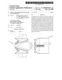
[0010]FIG. 1 is a simplified sectional side view of an illustrative embodiment of the multi-stage vehicle separation system of the present invention in a pre-separation condition thereof.
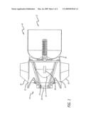
[0011]FIG. 2 is a simplified sectional side view of an illustrative embodiment of the multi-stage vehicle separation system of the present invention in a post-separation condition thereof.
DESCRIPTION OF THE INVENTION
[0012]Illustrative embodiments and exemplary applications will now be described with reference to the accompanying drawings to disclose the advantageous teachings of the present invention.
[0013]While the present invention is described herein with reference to illustrative embodiments for particular applications, it should be understood that the invention is not limited thereto. Those having ordinary skill in the art and access to the teachings provided herein will recognize additional modifications, applications, and embodiments within the scope thereof and additional fields in which the present invention would be of significant utility.
[0014]FIG. 1 is a simplified sectional side view of an illustrative embodiment of the multi-stage vehicle separation system of the present invention in a pre-separation condition thereof. As illustrated in FIG. 1, the multi-stage vehicle separation system 10 of the present invention includes a first lower stage 12 and a second upper stage 14. The upper stage 14 includes a nozzle 16. In accordance with the present teachings, a propellant 18 is embedded in the second stage nozzle volume 20 to effect stage separation. The embedded propellant 18 is ignited by a conventional armed fired device on receipt of a signal from a steering control section 22 of a guidance system (not shown). The embedded propellant may be any conventional propellant. In addition, the propellant may be ignited by a variety of wired or wireless fuses. Wired fused are preferred for safety reasons.
[0015]The second stage has control surfaces 24 and 26 and a plug 28 to provide thermal insulation and an environmental seal between the embedded propellant 18 and a second propellant (not shown) disposed in the second stage for propulsion thereof in a conventional manner. A V-Band clamp 30 serves to secure the lower stage 12 to the upper stage 14 in a conventional manner. The clamp is released under the control of the guidance system prior to the activation of the embedded propellant 18.
[0016]FIG. 2 is a simplified sectional side view of an illustrative embodiment of the multi-stage vehicle separation system of the present invention in a post-separation condition thereof. When a conventional `G-switch` (not shown) in the guidance system senses a drop in acceleration below a predetermined threshold, e.g., 1 g, the embedded propellant 18 is ignited. Hot gas and pressure generated by ignition of the embedded propellant in the second stage nozzle cavity exerts a force on the first stage booster 12 causing the first stage 12 to travel away from the second stage 14. The booster separation is equal to the force exerted on the booster divided by the mass of the spent booster 12. When the booster reaches a safe separation distance, the second stage motor ignition will occur per conventional practice.
[0017]Those skilled in the art will be able to determine how much propellant 18 to embed in the nozzle depending on the requirements of the application without undue experimentation.
[0018]Thus, the present invention has been described herein with reference to a particular embodiment for a particular application. Those having ordinary skill in the art and access to the present teachings will recognize additional modifications applications and embodiments within the scope thereof. For example, those of ordinary skill in the art will appreciate that the present teachings are not limited to two-stage vehicles. Moreover, the present teachings are not limited to vehicles adapted to fly in the air or in space. That is, the present teachings may be applied to vehicles in motion in any medium or a vacuum.
[0019]It is therefore intended by the appended claims to cover any and all such applications, modifications and embodiments within the scope of the present invention.
[0020]Accordingly,
Claims:
1. A vehicle separation system for use in a multi-stage vehicle having a
first stage and a second stage, said system comprising:a nozzle disposed
in said second stage of said vehicle, said nozzle being designed to burn
fuel propellant;fuel propellant embedded within said nozzle; andmeans for
activating said fuel propellant to separate said first stage from said
second stage and expel said first stage from said vehicle,whereupon on
ignition of said second stage, said second stage is propelled.
2-4. (canceled)
5. The invention of claim 1 further including means for retaining said first stage of said vehicle.
6. The invention of claim 5 wherein said means for retaining includes a V-Band clamp.
7-20. (canceled)
21. A multi-stage vehicle comprising:a first lower stage;a second upper stage;a nozzle disposed in said second stage, said nozzle being designed to burn fuel propellant; anda fuel propellant embedded in said nozzle; andmeans for selectively activating said fuel propellant in said nozzle to separate said first lower stage from said second upper stage.
22. A method for effecting separation of a multi-stage vehicle having a first lower stage and a second upper stage and a nozzle disposed in said second stage of said vehicle including the steps of:embedding a fuel propellant within said nozzle in said upper stage of said vehicle andactivating said propellant to separate said first stage from said second stage and expel said first stage from said vehicle,whereupon on ignition of said second stage, said second stage is propelled.
Description:
BACKGROUND OF THE INVENTION
[0001]1. Field of the Invention
[0002]The present invention relates to aeronautics, astronautics and hydraulics. More specifically, the present invention relates to systems and methods for effecting separation between stages of multi-stage vehicles.
[0003]2. Description of the Related Art
[0004]Multi-stage vehicles are used in a variety of applications including space, aerospace, and hydrospace applications. Separation is typically achieved by either an active or a passive approach. Active approaches include the use of retrorockets, explosives and/or mechanical arrangements (springs or other devices for storing energy). Passive approaches include arrangements for using drag to effect stage separation.
[0005]Unfortunately, the active approaches are typically somewhat complex, more costly and require considerably more space that passive approaches. Passive approaches, on the other hand, are beset by poor performance in designs where the upper stage has a diameter that is equal to or greater than that of the separating (lower) stage.
[0006]Hence, a need remains in the art for an improved system or method for separating stages of a multi-stage vehicle in flight that offers reliable performance without regard to the relative diameters of the stages and is space efficient, safe, simple and low in cost.
SUMMARY OF THE INVENTION
[0007]The need in the art is addressed by the multi-stage vehicle separation system and method of the present invention. In the most general embodiment, the invention includes a nozzle; a first fuel propellant disposed within the nozzle; and an arrangement for activating the first fuel propellant.
[0008]The nozzle is disposed in an upper stage of a two-stage vehicle. An arrangement such as a V-Band clamp is included for retaining the lower stage of the two-stage vehicle. Guidance commands release the lower stage and activate the first propellant in a timely manner to effectively separate the lower stage from the upper stage. The embedded propellant is activated with an arm fire device. Inasmuch as the nozzle is adapted to burn a second fuel propellant disposed external thereto, thermal insulation is provided between the embedded propellant and the upper stage fuel propellant as an optional safety measure.
[0009]Hence, the inventive system achieves an active separation on the booster by placing a small quantity of propellant in the dead volume between the second stage rocket motor nozzle and the booster dome.
BRIEF DESCRIPTION OF THE DRAWINGS
[0010]FIG. 1 is a simplified sectional side view of an illustrative embodiment of the multi-stage vehicle separation system of the present invention in a pre-separation condition thereof.
[0011]FIG. 2 is a simplified sectional side view of an illustrative embodiment of the multi-stage vehicle separation system of the present invention in a post-separation condition thereof.
DESCRIPTION OF THE INVENTION
[0012]Illustrative embodiments and exemplary applications will now be described with reference to the accompanying drawings to disclose the advantageous teachings of the present invention.
[0013]While the present invention is described herein with reference to illustrative embodiments for particular applications, it should be understood that the invention is not limited thereto. Those having ordinary skill in the art and access to the teachings provided herein will recognize additional modifications, applications, and embodiments within the scope thereof and additional fields in which the present invention would be of significant utility.
[0014]FIG. 1 is a simplified sectional side view of an illustrative embodiment of the multi-stage vehicle separation system of the present invention in a pre-separation condition thereof. As illustrated in FIG. 1, the multi-stage vehicle separation system 10 of the present invention includes a first lower stage 12 and a second upper stage 14. The upper stage 14 includes a nozzle 16. In accordance with the present teachings, a propellant 18 is embedded in the second stage nozzle volume 20 to effect stage separation. The embedded propellant 18 is ignited by a conventional armed fired device on receipt of a signal from a steering control section 22 of a guidance system (not shown). The embedded propellant may be any conventional propellant. In addition, the propellant may be ignited by a variety of wired or wireless fuses. Wired fused are preferred for safety reasons.
[0015]The second stage has control surfaces 24 and 26 and a plug 28 to provide thermal insulation and an environmental seal between the embedded propellant 18 and a second propellant (not shown) disposed in the second stage for propulsion thereof in a conventional manner. A V-Band clamp 30 serves to secure the lower stage 12 to the upper stage 14 in a conventional manner. The clamp is released under the control of the guidance system prior to the activation of the embedded propellant 18.
[0016]FIG. 2 is a simplified sectional side view of an illustrative embodiment of the multi-stage vehicle separation system of the present invention in a post-separation condition thereof. When a conventional `G-switch` (not shown) in the guidance system senses a drop in acceleration below a predetermined threshold, e.g., 1 g, the embedded propellant 18 is ignited. Hot gas and pressure generated by ignition of the embedded propellant in the second stage nozzle cavity exerts a force on the first stage booster 12 causing the first stage 12 to travel away from the second stage 14. The booster separation is equal to the force exerted on the booster divided by the mass of the spent booster 12. When the booster reaches a safe separation distance, the second stage motor ignition will occur per conventional practice.
[0017]Those skilled in the art will be able to determine how much propellant 18 to embed in the nozzle depending on the requirements of the application without undue experimentation.
[0018]Thus, the present invention has been described herein with reference to a particular embodiment for a particular application. Those having ordinary skill in the art and access to the present teachings will recognize additional modifications applications and embodiments within the scope thereof. For example, those of ordinary skill in the art will appreciate that the present teachings are not limited to two-stage vehicles. Moreover, the present teachings are not limited to vehicles adapted to fly in the air or in space. That is, the present teachings may be applied to vehicles in motion in any medium or a vacuum.
[0019]It is therefore intended by the appended claims to cover any and all such applications, modifications and embodiments within the scope of the present invention.
[0020]Accordingly,
User Contributions:
Comment about this patent or add new information about this topic:
| People who visited this patent also read: | |
| Patent application number | Title |
|---|---|
| 20100087057 | SEMICONDUCTOR DEVICE AND METHOD OF FABRICATING THE SAME |
| 20100087056 | METHOD FOR GATE HEIGHT CONTROL IN A GATE LAST PROCESS |
| 20100087055 | METHOD FOR GATE HEIGHT CONTROL IN A GATE LAST PROCESS |
| 20100087054 | METHOD FOR FORMING DEEP WELL OF POWER DEVICE |
| 20100087053 | METHOD FOR FABRICATING A SEMICONDUCTOR HAVING A GRADED PN JUNCTION |
Images included with this patent application:
 |  |
 |
| Similar patent applications: | |
| Date | Title |
|---|---|
| 2012-06-07 | Controllable digital solid state cluster thrusters for rocket propulsion and gas generation |
| 2009-08-20 | Micro-machined or micro-engraved safety and arming device |
| 2010-04-15 | Temperature responsive safety devices for munitions |
| 2008-11-13 | Multilayered microcavities and actuators incorporating same |
| 2010-07-29 | Gas generator and method for influencing a gas flow in a gas generator |
| New patent applications in this class: | |
| Date | Title |
|---|---|
| 2012-06-14 | Projectile that includes propulsion system and launch motor on opposing sides of payload and method |
| 2012-06-07 | Device for hardening a mechanical propulsion system connection for a mortar round and round comprising such a connection |
| 2011-08-11 | Missile head and method for separating a shroud from a fuselage of a missile |
| 2010-08-19 | Actuators for gun-fired projectiles and mortars |
| 2010-03-04 | Missile separation device |
| New patent applications from these inventors: | |
| Date | Title |
|---|---|
| 2014-05-01 | Method and apparatus for image stacking |
| 2011-12-22 | Multi channel electronic acceleration switch |
| Top Inventors for class "Ammunition and explosives" | |
| Rank | Inventor's name |
|---|---|
| 1 | Jahangir S. Rastegar |
| 2 | Eric Scheid |
| 3 | Richard T. Murray |
| 4 | Enrico R. Mutascio |
| 5 | Edward W. Sheridan |