Patent application title: Flow-Through Type Washing Device
Inventors:
Jack K. H. Wang (Taipei Hsien, TW)
IPC8 Class: AA47L2500FI
USPC Class:
401289
Class name: Brush, broom, or mop including feeder attached or attachable to conduit supply means
Publication date: 2009-03-05
Patent application number: 20090060628
Inventors list |
Agents list |
Assignees list |
List by place |
Classification tree browser |
Top 100 Inventors |
Top 100 Agents |
Top 100 Assignees |
Usenet FAQ Index |
Documents |
Other FAQs |
Patent application title: Flow-Through Type Washing Device
Inventors:
Jack K. H. Wang
Agents:
SQUIRE, SANDERS & DEMPSEY L.L.P.
Assignees:
Origin: SAN FRANCISCO, CA US
IPC8 Class: AA47L2500FI
USPC Class:
401289
Abstract:
A flow-through type washing device includes a connecting tube assembly, a
brush assembly and a handle assembly connected to the connecting tube
assembly. The handle assembly includes a tubular handle that defines a
fluid passage and that has a disc fitting tubular end, a partition disc
non-rotatably fitted to the disc fitting tubular end and having a port
such that a valve is operated to engage and disengage from the port, and
a tubular tightening member with an inner threaded surface. The inner
threaded surface is threadedably engaged with an outer threaded surface
of the handle to bring an annular shoulder of the tightening member to
abut against the partition disc so as to counteract a pressing force
applied to the partition disc when the valve is moved to engage the port.Claims:
1. A flow-through type washing device comprising:a tubular handle which
has an upstream tubular end that is adapted to be matably engaged with a
fitting of a washing water supply, and a tubular wall that extends from
said upstream tubular end in a lengthwise direction to terminate at a
disc fitting tubular end, and that defines a fluid passage communicating
said upstream tubular end with said disc fitting tubular end, said
tubular wall including a tightened segment which is adjacent to said disc
fitting tubular end, and which has an outer threaded surface surrounding
a tightening axis, and a passage accessing segment which is adjacent to
said tightened segment, and which is distal from said disc fitting
tubular end, said passage accessing segment having an access opening
which extends in a transverse direction relative to the lengthwise
direction to be communicated with said fluid passage;a partition disc
having outer and inner major surfaces opposite to each other, said
partition disc being configured such that said partition disc is
non-rotatably fitted to said disc fitting tubular end with said inner
major surface confronting said fluid passage, said inner major surface
having a valve seat which defines a port that extends through said outer
major surface;a valve stem mounted in said fluid passage, and having a
mount end which is shiftable substantially in a plane transverse to the
lengthwise direction between an aligned position, where said mount end is
aligned with said port, and a non-aligned position, where said mount end
is remote from said port;a valve head which is disposed on said mount
end, and which is configured to be fully engaged with said valve seat
when said mount is in the aligned position, and to be disengaged from
said valve seat when said mount end is in the non-aligned positions;an
actuator coupled with said valve stem to move said mount end between the
aligned and non-aligned positions, and having an operated end which is
externally accessible via said access opening; anda tubular tightening
member which has a smaller-diameter segment and a larger-diameter segment
opposite to each other in the lengthwise direction, and an annular
shoulder interposed therebetween and confronting said partition disc,
said larger-diameter segment having an inner threaded surface which is
configured to threadedly engage said outer threaded surface such that, by
virtue of threaded engagement between said outer and inner threaded
surfaces, said annular shoulder is brought to abut against said partition
disc so as to counteract a pressing force applied to said partition disc
when said mount end is moved from the non-aligned position to the aligned
position.
2. The flow-through type washing device according to claim 1, wherein said valve stem has a pivoted end which is opposite to said mount end in the transverse direction and which is pivotally mounted in said fluid passage about a pivot axis in the lengthwise direction such that said mount end is turnable about the pivot axis between the aligned and non-aligned positions;said washing device further comprising an actuated member which is disposed opposite to said pivoted end in the lengthwise direction, and which is revolvable with said pivoted end about the pivot axis;said actuator having an actuating end which is opposite to said operated end in the transverse direction, and which is configured to move said actuated member to revolve about the pivot axis to thereby couple said actuator with said valve stem.
3. The flow-through type washing device according to claim 2, wherein said partition disc has a post which extends from said inner major surface along the pivot axis such that, said pivoted end is revolvable about said post when said partition disc is fitted to said disc fitting tubular end, a water-tight seal which is disposed on said valve seat to ensure a water-tight engagement between said valve seat and said valve head when said mount end is in the aligned position, and a recess which is disposed in said inner major surface to accommodate said valve head when said mount end is in the non-aligned position.
4. The flow-through type washing device according to claim 3, wherein said tightened segment of said tubular wall has an inner annular surface which has at least one lengthwise extending protuberance that extends toward said disc fitting tubular end to terminate at a ledge surface, said partition disc having a cutout which extends from said inner major surface towards said outer major surface in the lengthwise direction to terminate at a marginal surface that is configured to mate with said ledge surface such that, once said partition disc is fitted to said disc fitting tubular end, said marginal surface is brought to abut against said ledge surface to thereby ensure non-rotation of said partition disc relative to said disc fitting tubular end.
5. The flow-through type washing device according to claim 4, further comprising a biasing spring which is disposed on said mount end, and which biases said valve head towards said inner major surface to apply the pressing force to said partition disc.
6. The flow-through type washing device according to claim 1, wherein said annular shoulder of said tubular tightening member has an O-ring which is disposed to abut against said outer major surface of said partition disc so as to ensure a fluid tight engagement between said annular shoulder and said partition disc.
7. The flow-through type washing device according to claim 1, further comprising:an elongated outer tube having opposite outer first and second ends;a tubular coupler which is disposed to connect said outer first end of said outer tube to said smaller-diameter segment of said tubular tightening member;an elongated inner tube having opposite inner first and second ends, and an inner intermediate segment interposed between said inner first and second ends, said inner first end being configured to be insertable into said outer tube through said outer second end with said inner intermediate segment extending beyond said outer second end, and to be slidable along said outer tube so as to permit varying of a distance between said inner second end and said outer second end;a tubular connector having a large-diameter wall and a small-diameter wall opposite to each other in the lengthwise direction, and an annular shoulder wall interposed therebetween, said large-diameter wall being configured to be insertable into said outer tube, said small-diameter wall being configured to be insertable into said inner first end, and to permit an end edge of said inner first end to abut against said annular shoulder wall such that said inner tube can be maintained in a retained and water-tight engagement with said outer tube; anda tubular lock which is disposed to releasably guard said inner intermediate segment against possible drifting movement relative to said outer second end so as to ensure the retained and water-tight engagement.
8. The flow-through type washing device according to claim 7, wherein said tubular lock includesa tubular joint having a lower tubular segment which is sleeved on said outer second end, and which is configured to abut against a tubular edge of said outer second end, and an upper tubular segment which is opposite to said lower tubular segment in the lengthwise direction, and which has an externally threaded surface;a collet member which has a tubular insert that is insertable into said upper tubular segment, and a collet portion that is opposite to said tubular insert in the lengthwise direction, and that is sleevable on said inner intermediate segment; anda tubular socket member having a lower tightening segment which has an internally threaded surface that is configured to mate with said externally threaded surface, and an upper conical socket segment which is opposite to said lower tightening segment, and which is configured to mate with said collet portion such that, when said internally threaded surface is engaged with said externally threaded surface, said collet portion is brought into tight engagement with said inner intermediate segment so as to ensure the retained and water-tight engagement.
9. The flow-through type washing device according to claim 1, further comprising:a scrubbing brush which includes a brush head which has a discharging port; anda tubular connector which is connected to said discharging port, said tubular connector having a surrounding wall which defines therein a passage that is fluidly communicated with said discharging port, and which is configured to be sleeved on said inner second end of said inner tube, an annular inner abutment which extends radially from said surrounding wall and which abuts against an end edge of said inner second end, and an annular inner clamping wall which extends from said annular inner abutment and which is spaced apart from said surrounding wall to define an annular space for insertion of said inner second end thereinto.
Description:
CROSS-REFERENCE TO RELATED APPLICATION
[0001]This application claims priority of Taiwanese Application No. 096214880, filed on Sep. 5, 2007.
BACKGROUND OF THE INVENTION
[0002]1. Field of the Invention
[0003]This invention relates to a flow-through type washing device, more particularly to a flow-through type washing device permitting washing water to flow therethrough to be used with a scrubbing brush.
[0004]2. Description of the Related Art
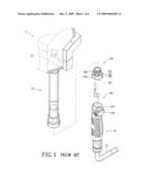
[0005]Referring to FIG. 1, a conventional washing device 1 is shown to include a brush 11, a tube 12 with an upper end connected to the brush 11, and a tubular handle 13 with an upper end 131 coupled with a lower end of the connecting tube 12 by a tubular tightening member 122. The handle 13 has a lower end matably engageable with a water pipe 14 such that water flows through the handle 13 and the tube 12 and is discharged through the brush 11. The tightening member 122 has a large-diameter segment which includes two parallel wall portions 125 and two arcuate wall portions 126 and which is matingly sleeved on the upper end 131 of the handle 13 and is bonded thereto using an adhesive or electromagnetic wave irradiation, a small-diameter segment with an externally threaded surface to be coupled with the tube 12, and a partition disc 124 which has a valve seat 123 formed therethrough. A valve 121 is mounted in the handle 13 and is actuated by an actuator 133 to permit or prevent water flowing through the valve seat 123.
[0006]However, the adhesive that bonds the tightening member 122 to the handle 13 may leak into the valve seat 123 during assembly to result in blocking of the valve seat 123, so that water cannot flow through the valve seat 123. In addition, the bonding force that holds the large-diameter segment of the tightening member 122 to the upper end 131 of the handle 13 may not be sufficient, so that detachment of the tube 12 from the handle 13 may result when scrubbing rigorously with the brush 11.
SUMMARY OF THE INVENTION
[0007]The object of the present invention is to provide a flow-through type washing device in which a tubular handle can be firmly connected to a connecting tube assembly.
[0008]According to this invention, the flow-through type washing device includes a tubular handle which has an upstream tubular end to be matably engaged with a fitting of a washing water supply, and a tubular wall that extends from the upstream tubular end in a lengthwise direction to terminate at a disc fitting tubular end, and that defines a fluid passage. The tubular wall includes a tightened segment with an outer threaded surface, and a passage accessing segment which has an access opening extending in a transverse direction. A partition disc has outer and inner major surfaces opposite to each other, and is configured to be non-rotatably fitted to the disc fitting tubular end with the inner major surface confronting the fluid passage. The inner major surface has a valve seat which defines a port extending through the outer major surface. A valve stem is mounted in the fluid passage, and has a mount end which is shiftable substantially in a plane transverse to the lengthwise direction between an aligned position, where the mount end is aligned with the port, and a non-aligned position, where the mount end is remote from the port. A valve head is disposed on the mount end, and is configured to be fully engaged with the valve seat when the mount end is in the aligned position, and is disengaged from the valve seat when the mount end is in the non-aligned position. An actuator is coupled with the valve stem to move the mount end between the aligned and non-aligned positions, and has an operated end that is accessible externally via the access opening so as to be manually operable. A tubular tightening member has a smaller-diameter segment and a larger-diameter segment opposite to each other in the lengthwise direction, and an annular shoulder interposed therebetween. The annular shoulder confronts the partition disc, and has an inner threaded surface to engage the outer threaded surface such that, by virtue of the threaded engagement between the outer and inner threaded surfaces, the annular shoulder is brought to abut against the partition disc so as to counteract a pressing force applied to the partition disc when the mount end is moved from the non-aligned position to the aligned position.
BRIEF DESCRIPTION OF THE DRAWINGS
[0009]Other features and advantages of the present invention will become apparent in the following detailed description of the preferred embodiment of the invention, with reference to the accompanying drawings, in which:
[0010]FIG. 1 is an exploded perspective view of a conventional washing device;
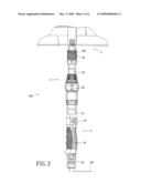
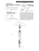
[0011]FIG. 2 is a schematic view of the preferred embodiment of a flow-through type washing device according to this invention;
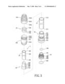
[0012]FIG. 3 is an exploded perspective view of a connecting tube assembly of the preferred embodiment;
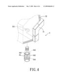
[0013]FIG. 4 is a fragmentary perspective view of a brush assembly of the preferred embodiment;
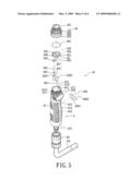
[0014]FIG. 5 is an exploded perspective view of a handle assembly of the preferred embodiment and a washing water pipe used therewith; and
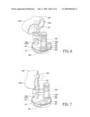
[0015]FIGS. 6 and 7 are perspective views of a valve unit of the preferred embodiment in aligned and non-aligned positions, respectively.
DETAILED DESCRIPTION OF THE PREFERRED EMBODIMENT
[0016]Referring to FIG. 2, the preferred embodiment of a flow-through type washing device 100 according to the present invention is shown to comprise a handle assembly 4, a connecting tube assembly 2, and a brush assembly 3.
[0017]Referring to FIGS. 2, and 5 to 7, the handle assembly 4 includes a tubular handle 41, a partition disc 42, and a valve unit 44.
[0018]The tubular handle 41 has an upstream tubular end 413 that is adapted to matably engage with a fitting 43 of a washing water supply 101, and a tubular wall 414 that extends from the upstream tubular end 413 in a lengthwise direction to terminate at a disc fitting tubular end 415, and that defines a fluid passage 416 communicating the upstream tubular end 413 with the disc fitting tubular end 415. The tubular wall 414 includes a tightened segment 417 which is adjacent to the disc fitting tubular end 415, and which has an outer threaded surface 411 surrounding a tightening axis, and a passage accessing segment 418 which is adjacent to the tightened segment 417, and which is distal from the disc fitting tubular end 415. The passage accessing segment 418 has an access opening 419 which extends in a transverse direction relative to the lengthwise direction to be communicated with the fluid passage 416. In addition, the tightened segment 417 has an inner annular surface which has a pair of lengthwise extending protuberances 412 each extending toward the disc fitting tubular end 415 to terminate at a ledge surface 4121.
[0019]The partition disc 42 has outer and inner major surfaces 421,427 opposite to each other, and a cutout which extends from the inner major surface 427 towards the outer major surface 421 in the lengthwise direction to terminate at two marginal surfaces 426 that are configured to mate with and to abut against the ledge surfaces 4121 of the tightened segment 417, respectively. Thus, the partition disc 42 is non-rotatably fitted to the disc fitting tubular end 415 with the inner major surface 427 confronting the fluid passage 416. The inner major surface 427 has a valve seat which defines a port 423 that extends through the outer major surface 421. A water-tight seal 424 is disposed on the valve seat. A post 422 extends from the inner major surface 427 along a pivot axis in the lengthwise direction. A recess 425 is formed in the inner major surface 427.
[0020]The valve unit 44 includes a valve stem 442, a valve head 445, a biasing spring 444, an actuated member 441, and an actuator 440. The valve stem 442 is mounted in the fluid passage 416, and has a mount end 4421 and a pivoted end 4422 opposite to each other in the transverse direction. The pivoted end 4422 is sleeved on and is revolvable about the post 422 such that the mount end 4421 is turnable about the pivot axis between an aligned position (FIG. 6), where the mount end 4421 is aligned with the port 423, and a non-aligned position (FIG. 7), where the mount end 4421 is remote from the port 423. The valve head 445 is disposed on the mount end 4421, and is fully engaged with the port 423 when the mount end 4421 is in the aligned position, and is disengaged from the port 423 when the mount end 4421 is in the non-aligned position. Referring to FIG. 6, the water-tight seal 424 can ensure a water-tight engagement between the port 423 and the valve head 445 when the mount end 4421 is in the aligned position. Referring to FIG. 7, the recess 425 can accommodate the valve head 445 when the mount end 4421 is in the non-aligned position. The biasing spring 444 is disposed on the mount end 4421, and biases the valve head 445 towards the inner major surface 427. The actuated member 441 is integrally formed with and is disposed opposite to the pivoted end 4422 in the lengthwise direction so as to be revolvable with the pivoted end 4422 about the pivot axis. The actuator 440 has an actuating end 4401 which is connected to the actuated member 441 and which moves the actuated member 441 to revolve about the pivot axis, and an operated end 4402 which is opposite to the actuating end 4401 in the transverse direction and which is externally accessible via the access opening 419 so as to be manually operable.
[0021]Referring to FIGS. 2, 3 and 5, the connecting tube assembly 2 includes a tubular tightening member 20, an elongated outer tube 21, a tubular coupler 22, an elongated inner tube 23, a tubular connector 24, and a tubular lock 25.
[0022]The tubular tightening member 20 has a smaller-diameter segment 201 and a larger-diameter segment 203 opposite to each other in the lengthwise direction, and an annular shoulder 202 interposed therebetween and confronting the partition disc 42. The larger-diameter segment 203 has an inner threaded surface 205 which is configured to mate with the outer threaded surface 411 of the handle 41 such that, by virtue of threaded engagement between the outer and inner threaded surfaces 411,205, the annular shoulder 202 is brought to abut against the partition disc 42 so as to counteract a pressing force applied to the partition disc 42 when the mount end 4421 is moved from the non-aligned position to the aligned position. Preferably, the annular shoulder 202 has an O-ring 204 which is disposed to abut against the outer major surface 421 of the partition disc 42 so as to ensure the fluid tight engagement between the annular shoulder 202 and the partition disc 42.
[0023]The outer tube 21 has opposite outer first and second ends 211,212.
[0024]The tubular coupler 22 is disposed to connect the outer first end 211 of the outer tube 21 to the smaller-diameter segment 201 of the tubular tightening member 20. Specifically, the tubular coupler 22 includes a smaller-diameter portion 221 which is inserted into the outer first end 211 of the outer tube 21, and a surrounding portion 222 which surrounds the smaller-diameter portion 221 and which is spaced apart from the smaller-diameter portion 221 by a shoulder 223 to cooperatively engage the outer first end 211, with an end edge of the outer first end 211 abutting against the shoulder 223. A water-tight ring 220 is sleeved on the smaller-diameter portion 221 for preventing water leakage from the outer tube 21. The tubular coupler 22 further includes an inner threaded portion 224 which extends from the shoulder 223 to be threadedly engaged with the smaller-diameter segment 201 of the tubular tightening member 20, and a larger-diameter portion 225 which is disposed to surround the larger-diameter segment 203 of the tubular tightening member 20. An upper edge of the tubular tightening member 20 abuts against the shoulder 223 and an O-ring 226 when the inner threaded portion 224 is threadedly engaged with the smaller-diameter segment 201.
[0025]The inner tube 23 has opposite inner first and second ends 231,232, and an inner intermediate segment 233 interposed therebetween. The inner first end 231 is dimensioned to be insertable into the outer tube 21 through the outer second end 212 with the inner intermediate segment 233 extending beyond the outer second end 212, and to be slidable along the outer tube 21 so as to permit varying of a distance between the inner second end 232 and the outer second end 212.
[0026]The tubular connector 24 has a large-diameter wall 242 and a small-diameter wall 241 opposite to each other in the lengthwise direction, and an annular shoulder wall 243 interposed therebetween. The large-diameter wall 242 is configured to be insertable into the outer tube 21. The small-diameter wall 241 is configured to be insertable into the inner first end 231, and to permit an end edge of the inner first end 231 to abut against the annular shoulder wall 243 such that the inner tube 23 can be maintained in a retained and water-tight engagement with the outer tube 21. Preferably, a plurality of O-rings are sleeved on the small-diameter and large-diameter walls 241,242 for water-tight purposes.
[0027]The tubular lock 25 is disposed to releasably guard the inner tube 23 against possible drifting movement relative to the outer tube 21 so as to ensure the retained and water-tight engagement between the inner tube 23 and the outer tube 21. Specifically, the tubular lock 25 includes a tubular joint 252, a collet member 253, and a tubular socket member 254. The tubular joint 252 has a lower tubular segment 2521 which is sleeved on the outer second end 212 and which has an annular protrusion 251 to abut against a tubular edge of the outer second end 212, and an upper tubular segment 2522 which is opposite to the lower tubular segment 2521 in the lengthwise direction, and which has an externally threaded surface 2523. The collet member 253 has a tubular insert 255 which is retainingly inserted in the upper tubular segment 2522 and which abuts against the annular protrusion 251, and a collet portion 256 which is opposite to the tubular insert 255 in the lengthwise direction, and which is sleevable on the inner intermediate segment 233. The tubular socket member 254 has a lower tightening segment 2541 which has an internally threaded surface 2542 that is configured to mate with the externally threaded surface 2523, and an upper conical socket segment 2543 which is opposite to the lower tightening segment 2541, and which is configured to mate with the collet portion 256. Thus, when the internally threaded surface 2542 and the externally threaded surface 2523 are engaged, the collet portion 256 is brought into a tight engagement with the inner intermediate segment 233 so as to ensure the retained and water-tight engagement between the inner and outer tubes 23,21. Hence, the distance between the inner second end 232 and the outer second end 212 can be fixed to facilitate use of the washing device 100.
[0028]Referring to FIGS. 2 and 4, the brush assembly 3 includes a scrubbing brush 31 and a tubular connector 34. The brush 31 includes a brush head 32 which has a discharging port 321. The tubular connector 34 is connected to the discharging port 321. Specifically, the tubular connector 34 has a surrounding wall 342 which defines therein a passage 344 that is fluidly communicated with the discharging port 321, and which is configured to be sleeved on the inner second end 232 of the inner tube 23, an annular inner abutment 343 which extends radially from the surrounding wall 342 and which abuts against an end edge of the inner second end 232, and an annular inner clamping wall 345 which extends from the annular inner abutment 343 and which is spaced apart from the surrounding wall 342 to define an annular space for insertion of the inner second end 232 thereinto.
[0029]As illustrated, by virtue of the threaded engagement between the outer threaded surface 411 of the handle 41 and the inner threaded surface 205 of the tubular tightening member 20, the handle assembly 4 can be firmly connected to the connecting tube assembly 2.
[0030]While the present invention has been described in connection with what is considered the most practical and preferred embodiment, it is understood that this invention is not limited to the disclosed embodiment but is intended to cover various arrangements included within the spirit and scope of the broadest interpretations and equivalent arrangements.
User Contributions:
comments("1"); ?> comment_form("1"); ?>Inventors list |
Agents list |
Assignees list |
List by place |
Classification tree browser |
Top 100 Inventors |
Top 100 Agents |
Top 100 Assignees |
Usenet FAQ Index |
Documents |
Other FAQs |
User Contributions:
Comment about this patent or add new information about this topic:
Images included with this patent application:
 |  |
 |  |
 |  |
 |
| Similar patent applications: | |
| Date | Title |
|---|---|
| 2012-07-26 | Portable washing device |
| 2011-06-30 | Oral cavity cleaning device |
| 2009-03-05 | Microfluidic surface treatment device |
| 2011-10-06 | Mascara dispensing device |
| 2012-05-17 | High cleaning dentifrice compositions |
| New patent applications in this class: | |
| Date | Title |
|---|---|
| 2014-08-21 | Fluid application device |
| 2009-10-22 | Liquid dispensing brush assembly for a floor scrubber |
| 2008-09-11 | Toothbrush with toothpaste in handle |
| 2008-08-21 | Window cleaning apparatus with deionization cartridge |
| 2008-08-21 | Portable conversion washing device |
| Top Inventors for class "Coating implements with material supply" | |
| Rank | Inventor's name |
|---|---|
| 1 | Jean-Louis Gueret |
| 2 | Leo Clifford Pires |
| 3 | Roger Hwang |
| 4 | Rahul Bose |
| 5 | Timothy Thorpe |