Patent application title: Mounting apparatus for storage device
Inventors:
Chang-Chun Liu (Shenzhen, CN)
Xiao-Lin Gan (Shenzhen, CN)
Yu-Kuang Ho (Tu-Cheng, TW)
Assignees:
HONG FU JIN PRECISION INDUSTRY (ShenZhen) CO., LTD.
HON HAI PRECISION INDUSTRY CO., LTD.
IPC8 Class: AA47B9606FI
USPC Class:
2482065
Class name: Brackets specially mounted or attached by magnet
Publication date: 2009-03-05
Patent application number: 20090057511
holding a storage device defining a plurality of
mounting holes in a side thereof includes a bracket and a plurality of
attaching members. The bracket includes a first sidewall and a second
sidewall parallel to the first sidewall, the first sidewall defines a
plurality of through holes, corresponding to the mounting holes. Each
attaching member includes a base and a protrusion formed on the base, and
the base attaches to the outside surface of the first sidewall of the
bracket via magnetism generated between the base and the first sidewall,
and the protrusions extends though the through holes of the first
sidewall and inserts into the corresponding mounting hole of the storage
device.Claims:
1. A mounting apparatus for holding a storage device with a plurality of
mounting holes defined in a side thereof, the mounting apparatus
comprising:a bracket adapted for accommodating the storage device
therein, and comprising a first sidewall and a second sidewall parallel
to the first sidewall, the first sidewall comprising a plurality of
through holes, corresponding to the mounting holes; anda plurality of
attaching members each comprising a base and a protrusion formed on the
base, the base attached to an outside surface of the first sidewall of
the bracket via magnetism generated between the base and the first
sidewall, and the protrusions extending though the through holes of the
first sidewall and inserting into the corresponding mounting holes of the
storage device.
2. The mounting apparatus as claimed in claim 1, wherein a handle is formed on the base for facilitating manipulating each of the attaching member, the mounting apparatus further comprises a chassis having a side panel which abutted against the attaching member.
3. The mounting apparatus as claimed in claim 1, wherein the base has a magnetic coating around the protrusion, an outside surface of the first sidewall is coated a magnetic coating for generating magnetism in cooperation with the base.
4. The mounting apparatus as claimed in claim 1, wherein the base or the whole attaching member is made of magnetic material, an outside surface of the first sidewall of the bracket is made of steel.Description:
BACKGROUND
[0001]1. Field of the Invention
[0002]The present invention relates to mounting apparatuses, and more particularly to a mounting apparatus for an electronic storage device, which allows convenient installation and removal of the storage device.
[0003]2. Description of Related Art
[0004]An electronic apparatus, such as a typical desktop computer, a tower computer, a server, and the like, usually includes storage devices, such as hard disk drives, compact disk read-only memory (CD-ROM) drives, digital video disc (DVD) drives, floppy disk drives, and the like. These devices are typically added to increase the functionality of the electronic apparatus as desired by a user. However, the installation of such devices in the electronic apparatus is labor-intensive.
[0005]The installation of a hard disk drive in a computer typically involves the use of screws to attach the hard disk drive to a bracket of a computer chassis. However, these screws are usually too small and difficult to handle. Additionally, because of their small size, the screws are easily dropped, by an assembler, into the computer.
[0006]To address the aforementioned problems, a plurality of mounting apparatuses is invented to reduce the number of needed screws. For example, a pair of detachable rails is attached to opposite sides of a storage device with screws. The storage device is then slid into and secured to a drive bracket. However, the aforesaid mounting apparatuses is still complicated for user to manipulate the rails when assembling or disassembling the storage device.
[0007]What is needed, therefore, is a mounting apparatus which facilitates assembling or disassembling a storage device.
SUMMARY
[0008]In one preferred embodiment, a mounting apparatus for holding a storage device defining a plurality of mounting holes in a side thereof includes a bracket and a plurality of attaching members. The bracket includes a first sidewall and a second sidewall parallel to the first sidewall, the first sidewall defines a plurality of through holes, corresponding to the mounting holes. Each attaching member includes a base and a protrusion formed on the base, and the base attaches to the outside surface of the first sidewall of the bracket via magnetism generated between the base and the first sidewall, and the protrusions extends though the through holes of the first sidewall and inserts into the corresponding mounting hole of the storage device.
BRIEF DESCRIPTION OF THE DRAWINGS
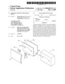
[0009]FIG. 1 is an exploded, isometric view of a mounting apparatus with a storage device in accordance with an embodiment of the present invention;
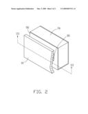
[0010]FIG. 2 is an assembled view of FIG. 1; and
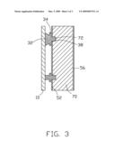
[0011]FIG. 3 is a cross-sectional view of FIG. 2, taken along line III-III.
DETAILED DESCRIPTION
[0012]Referring to FIG. 1, in a preferred embodiment of the invention, a mounting apparatus is provided for holding a storage device 70 with a plurality of mounting holes 72 defined in a side thereof. The mounting apparatus includes a bracket 50 for accommodating the storage device 70 therein, a chassis having a side panel 10, and a plurality of attaching members 30 attached to the bracket 50 to secure the storage device 70.
[0013]The bracket 50 includes a first sidewall 52 made of steel, a second sidewall 56 and a bottom wall 58. The first sidewall 52 and the second sidewall 56 are parallel to each other and perpendicular to the bottom wall 58. The bottom wall 58 connects bottom edges of the first sidewall 52 and the second sidewall 56. Outside surface of the first sidewall 52 has a magnetic coating. A plurality of through holes 520 is defined in the first sidewall 52, corresponding to the mounting holes 72 of the storage device 70.
[0014]Each attaching member 30 includes a base 34 and a protrusion 38 formed on one side surface of the base 34. A trapeziform handle 32 is formed on the other side surface of the base 34. The base 34 has a magnetic coating disposed on the side surface around the protrusion 38, or the base 34 is made of magnetic material. In further embodiments the attaching member 30 may be made of magnetic material.
[0015]Referring to FIGS. 2 and 3, in assembly, the bracket 50 is installed in the chassis. The protrusions 38 of the attaching member 30 are extended through the through holes 520 of the first sidewall 52 and inserted into the corresponding mounting holes 72 of the storage device 70. The base 34 is attached to the outside surface of the first sidewall 52 of the bracket 50 by magnetism generated between the base 34 and the first sidewall 52. The side panel 10 is assembled in the chassis and the inside surface of the side panel 10 abuts against the handle 32. The storage device 70 is fixed in the bracket 50.
[0016]To detach the storage device 70, the side panel 10 is detached from the chassis, the attaching members 30 are detached from the storage device 70 and the bracket 50 by pulling the handles 32 outward.
Claims:
1. A mounting apparatus for holding a storage device with a plurality of
mounting holes defined in a side thereof, the mounting apparatus
comprising:a bracket adapted for accommodating the storage device
therein, and comprising a first sidewall and a second sidewall parallel
to the first sidewall, the first sidewall comprising a plurality of
through holes, corresponding to the mounting holes; anda plurality of
attaching members each comprising a base and a protrusion formed on the
base, the base attached to an outside surface of the first sidewall of
the bracket via magnetism generated between the base and the first
sidewall, and the protrusions extending though the through holes of the
first sidewall and inserting into the corresponding mounting holes of the
storage device.
2. The mounting apparatus as claimed in claim 1, wherein a handle is formed on the base for facilitating manipulating each of the attaching member, the mounting apparatus further comprises a chassis having a side panel which abutted against the attaching member.
3. The mounting apparatus as claimed in claim 1, wherein the base has a magnetic coating around the protrusion, an outside surface of the first sidewall is coated a magnetic coating for generating magnetism in cooperation with the base.
4. The mounting apparatus as claimed in claim 1, wherein the base or the whole attaching member is made of magnetic material, an outside surface of the first sidewall of the bracket is made of steel.
Description:
BACKGROUND
[0001]1. Field of the Invention
[0002]The present invention relates to mounting apparatuses, and more particularly to a mounting apparatus for an electronic storage device, which allows convenient installation and removal of the storage device.
[0003]2. Description of Related Art
[0004]An electronic apparatus, such as a typical desktop computer, a tower computer, a server, and the like, usually includes storage devices, such as hard disk drives, compact disk read-only memory (CD-ROM) drives, digital video disc (DVD) drives, floppy disk drives, and the like. These devices are typically added to increase the functionality of the electronic apparatus as desired by a user. However, the installation of such devices in the electronic apparatus is labor-intensive.
[0005]The installation of a hard disk drive in a computer typically involves the use of screws to attach the hard disk drive to a bracket of a computer chassis. However, these screws are usually too small and difficult to handle. Additionally, because of their small size, the screws are easily dropped, by an assembler, into the computer.
[0006]To address the aforementioned problems, a plurality of mounting apparatuses is invented to reduce the number of needed screws. For example, a pair of detachable rails is attached to opposite sides of a storage device with screws. The storage device is then slid into and secured to a drive bracket. However, the aforesaid mounting apparatuses is still complicated for user to manipulate the rails when assembling or disassembling the storage device.
[0007]What is needed, therefore, is a mounting apparatus which facilitates assembling or disassembling a storage device.
SUMMARY
[0008]In one preferred embodiment, a mounting apparatus for holding a storage device defining a plurality of mounting holes in a side thereof includes a bracket and a plurality of attaching members. The bracket includes a first sidewall and a second sidewall parallel to the first sidewall, the first sidewall defines a plurality of through holes, corresponding to the mounting holes. Each attaching member includes a base and a protrusion formed on the base, and the base attaches to the outside surface of the first sidewall of the bracket via magnetism generated between the base and the first sidewall, and the protrusions extends though the through holes of the first sidewall and inserts into the corresponding mounting hole of the storage device.
BRIEF DESCRIPTION OF THE DRAWINGS
[0009]FIG. 1 is an exploded, isometric view of a mounting apparatus with a storage device in accordance with an embodiment of the present invention;
[0010]FIG. 2 is an assembled view of FIG. 1; and
[0011]FIG. 3 is a cross-sectional view of FIG. 2, taken along line III-III.
DETAILED DESCRIPTION
[0012]Referring to FIG. 1, in a preferred embodiment of the invention, a mounting apparatus is provided for holding a storage device 70 with a plurality of mounting holes 72 defined in a side thereof. The mounting apparatus includes a bracket 50 for accommodating the storage device 70 therein, a chassis having a side panel 10, and a plurality of attaching members 30 attached to the bracket 50 to secure the storage device 70.
[0013]The bracket 50 includes a first sidewall 52 made of steel, a second sidewall 56 and a bottom wall 58. The first sidewall 52 and the second sidewall 56 are parallel to each other and perpendicular to the bottom wall 58. The bottom wall 58 connects bottom edges of the first sidewall 52 and the second sidewall 56. Outside surface of the first sidewall 52 has a magnetic coating. A plurality of through holes 520 is defined in the first sidewall 52, corresponding to the mounting holes 72 of the storage device 70.
[0014]Each attaching member 30 includes a base 34 and a protrusion 38 formed on one side surface of the base 34. A trapeziform handle 32 is formed on the other side surface of the base 34. The base 34 has a magnetic coating disposed on the side surface around the protrusion 38, or the base 34 is made of magnetic material. In further embodiments the attaching member 30 may be made of magnetic material.
[0015]Referring to FIGS. 2 and 3, in assembly, the bracket 50 is installed in the chassis. The protrusions 38 of the attaching member 30 are extended through the through holes 520 of the first sidewall 52 and inserted into the corresponding mounting holes 72 of the storage device 70. The base 34 is attached to the outside surface of the first sidewall 52 of the bracket 50 by magnetism generated between the base 34 and the first sidewall 52. The side panel 10 is assembled in the chassis and the inside surface of the side panel 10 abuts against the handle 32. The storage device 70 is fixed in the bracket 50.
[0016]To detach the storage device 70, the side panel 10 is detached from the chassis, the attaching members 30 are detached from the storage device 70 and the bracket 50 by pulling the handles 32 outward.
User Contributions:
Comment about this patent or add new information about this topic:
Images included with this patent application:
 |  |
 |  |
| Similar patent applications: | |
| Date | Title |
|---|---|
| 2010-01-07 | Mounting apparatus for storage device |
| 2010-10-28 | Mounting apparatus for storage device |
| 2011-03-03 | Mounting apparatus for data storage device |
| 2011-04-28 | Mounting apparatus for data storage device |
| 2011-04-28 | Mounting apparatus for data storage device |
| New patent applications in this class: | |
| Date | Title |
|---|---|
| 2016-06-16 | Computing accessory mounting apparatus |
| 2016-06-02 | Clip-on mounting assembly for musical instruments |
| 2016-05-19 | Magnetic universal mounting assembly |
| 2016-05-05 | Magnetic attraction-fixing assembly and a rotating support structure for a portable device having the magnetic attraction-fixing assembly |
| 2016-04-14 | Automatic locking mechanism and electronic device therewith |
| New patent applications from these inventors: | |
| Date | Title |
|---|---|
| 2020-04-16 | Self-guided object detection in regular images |
| 2009-06-25 | Computer enclosure |
| 2009-06-25 | Charging circuit of portable device |
| Top Inventors for class "Supports" | |
| Rank | Inventor's name |
|---|---|
| 1 | Jeffrey D. Carnevali |
| 2 | Yun-Lung Chen |
| 3 | Wen-Tang Peng |
| 4 | Zheng-Heng Sun |
| 5 | Zhan-Yang Li |