Patent application title: Eavestrough cover with clip
Inventors:
Stephane Brochu (St-Romauld, CA)
IPC8 Class: AE04D13064FI
USPC Class:
52 12
Class name: Static structures (e.g., buildings) cover with surface water receiver at eave or valley with separator; e.g., strainer
Publication date: 2009-03-05
Patent application number: 20090056234
Inventors list |
Agents list |
Assignees list |
List by place |
Classification tree browser |
Top 100 Inventors |
Top 100 Agents |
Top 100 Assignees |
Usenet FAQ Index |
Documents |
Other FAQs |
Patent application title: Eavestrough cover with clip
Inventors:
Stephane Brochu
Agents:
Eric Fincham
Assignees:
Origin: LAC BROME, QC CA
IPC8 Class: AE04D13064FI
USPC Class:
52 12
Abstract:
An eavestrough cover for use with an eavestrough, the eavestrough cover
having a central horizontal portion, a plurality of apertures formed in
the central horizontal portion, a first side of the central horizontal
portion having a structure for engaging an eavestrough recess, and a
downwardly extending wall formed along the second side of the eavestrough
cover, the arrangement being such that water from a drip edge of the
house may enter the eavestrough. In preferred embodiments, clip members
are utilized for securing the eavestrough cover (and eavestrough) to the
facia of an adjacent structure on which the eavestrough is mounted.Claims:
1. An eavestrough cover for use with an eavestrough having an eavestrough
recess defined by an eavestrough front wall, eavestrough top wall and a
flange extending downwardly from said eavestrough top wall, the
eavestrough cover comprising:a central horizontal portion having first
and second sides;a plurality of apertures formed in said central
horizontal portion;said first side having a structure for engaging said
eavestrough recess; anda downwardly extending wall formed along said
second side of said eavestrough cover.
2. The eavestrough cover of claim 1 wherein said downwardly extending wall has a length sufficient to reach a bottom wall of said eavestrough.
3. The eavestrough cover of claim 1 further including at least one clip member, said clip member having a first wall for securement to an adjacent structure, and a second wall designed to be secured to said central horizontal portion.
4. The eavestrough cover of claim 2 further including a plurality of apertures formed in said downwardly extending wall.
5. The eavestrough cover of claim 3 wherein said central horizontal portion has, on said second side thereof, a folded portion to form a recess between said horizontal central portion and said folded portion.
6. The eavestrough cover of claim 5 wherein said clip member engages within said recess.
7. The eavestrough cover of claim 1 further including an aperture in said first wall of said clip member.
8. The eavestrough member of claim 6 wherein said clip member includes a diagonally extending wall between said first wall and said second wall.
9. The eavestrough cover of claim 1 wherein said at least one clip member has a plurality of fingers extending downwardly from said second wall, said fingers being designed to engage within said apertures formed in said central horizontal portion.
10. The eavestrough cover of claim 1 wherein said eavestrough cover is formed of an aluminum material.
11. In combination, an eavestrough and an eavestrough cover therefore, said eavestrough comprising an eavestrough rear wall, an eavestrough bottom wall, and an eavestrough front wall, an eavestrough top wall and a flange extending downwardly from said eavestrough top wall, an eavestrough recess being defined by said eavestrough top wall, said eavestrough front wall and said flange;said eavestrough cover comprising:a central horizontal portion having first and second sides, a plurality of apertures formed in said central horizontal portion;said first side being retained within said eavestrough recess;a downwardly extending wall formed along said second side of said eavestrough cover; andat least one clip member having a first wall for securement to an adjacent structure, and a second wall secured to said second horizontal portion.
12. The eavestrough and eavestrough cover of claim 11 wherein said downwardly extending wall has a length sufficient to reach a bottom wall of said eavestrough.
13. The eavestrough and eavestrough cover of claim 12 wherein said downwardly extending wall has a longitudinally extending bend line formed therein.
14. The eavestrough and eavestrough cover of claim 12 further including a plurality of apertures formed in said downwardly extending wall.
15. The eavestrough and eavestrough cover of claim 11 wherein said central horizontal portion has, on said second side thereof, a folded portion to form a recess between said horizontal central portion and said folded portion.
16. The eavestrough and eavestrough cover of claim 15 wherein said clip member engages within said recess.
17. The eavestrough and eavestrough cover of claim 11 further including an aperture in said first wall of said clip member.
18. The eavestrough and eavestrough cover of claim 16 wherein said clip member includes a diagonally extending wall between said first wall and said second wall.
19. The eavestrough and eavestrough cover of claim 11 wherein said at least one clip member has a plurality of fingers extending downwardly from said second wall, said fingers being designed to engage within said apertures formed in said central horizontal portion.
20. The eavestrough and eavestrough cover of claim 11 wherein said eavestrough cover is formed of an aluminum material.
Description:
FIELD OF THE INVENTION
[0001]The present invention relates to eavestrough covers.
BACKGROUND OF THE INVENTION
[0002]The use of eavestrough covers is well known in the prior art and there have been many proposals for different types of shields. The purpose of the shield is essentially to permit passage of rainwater from the roof to the eavestrough while protecting the drain from extraneous foreign matter such as leaves and the like.
[0003]Different approaches have been taken to the design of eavestrough covers. Some of the proposed eavestrough covers are secured directly to the eavestrough while others are secured to the wall or roof of the adjacent structure.
SUMMARY OF THE INVENTION
[0004]It is an object of the present invention to provide an eavestrough cover which incorporates a clip member for securement and which permits drainage from a drip edge associated with the roof.
[0005]According to one aspect of the present invention there provided an eavestrough cover for use with an eavestrough having an eavestrough recess defined by an eavestrough front wall, eavestrough top wall and a flange extending downwardly from said eavestrough top wall, the eavestrough cover comprising a central horizontal portion having first and second sides, a plurality of apertures formed in the central horizontal portion, the first side having a structure for engaging the eavestrough recess, and a downwardly extending wall formed along said second side of the eavestrough cover.
[0006]According to a further aspect of the present invention, there is provided in combination, an eavestrough and an eavestrough cover therefore, the eavestrough comprising an eavestrough rear wall, an eavestrough bottom wall, and an eavestrough front wall, an eavestrough top wall and a flange extending downwardly from the eavestrough top wall, an eavestrough recess being defined by the eavestrough top wall, the eavestrough front wall and the flange, the eavestrough cover comprising, a central horizontal portion having first and second sides, a plurality of apertures formed in the central horizontal portion, the first side being retained within the eavestrough recess, a downwardly extending wall formed along the second side of the eavestrough cover, and at least one clip member having a first wall for securement to an adjacent structure, and a second wall secured to the second horizontal portion.
[0007]The eavestrough of the present invention may be placed on the eavestrough such that a first side near the front wall of the eavestrough engages in a recess formed therein. Adjacent the rear wall of the eavestrough, there is provided a downwardly extending wall from the eavestrough cover which preferably engages or rests on the bottom wall of the eavestrough. The arrangement is such that the drip edge may fit between the rear wall of the eavestrough and the downwardly extending wall of the eavestrough cover. A plurality of apertures are provided in the downwardly extending wall to permit water flow into the main eavestrough portion.
[0008]In the preferred embodiments, a clip member is utilized to secure the eavestrough cover to the adjacent facia. The clip member may take different forms as will be discussed in the detailed description of the invention.
BRIEF DESCRIPTION OF THE DRAWINGS
[0009]Having thus generally described the invention, reference will be made to the drawings illustrating an embodiment thereof, in which:
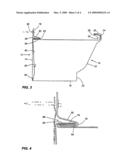
[0010]FIG. 1 is a perspective of an eavestrough cover according to one embodiment of the present invention;
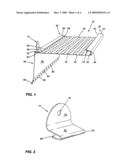
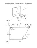
[0011]FIG. 2 is a perspective view of a clip member associated with the eavestrough cover;
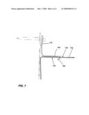
[0012]FIG. 3 is a side elevational view thereof with the eavestrough being shown in dashes dot lines;
[0013]FIG. 4 is a detailed side elevational view showing the engagement of the clip member with the eavestrough cover;
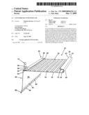
[0014]FIG. 5 is a perspective view of a further embodiment of a clip member;
[0015]FIG. 6 is a side elevational view showing the engagement of the clip member with the eavestrough cover; and
[0016]FIG. 7 is a cross sectional view illustrating engagement of the clip member with the eavestrough cover.
DETAILED DESCRIPTION OF THE INVENTION
[0017]Referring to the drawings in greater detail and by reference characters thereto, there is illustrated in FIGS. 1 to 4 a first version of a eavestrough cover and which cover is generally designated by reference numeral 10.
[0018]Eavestrough cover 10 is designed to be used with an eavestrough generally designated by reference numeral 12 and shown in dot dash lines. Eavestrough 12 has a rear wall 14, a bottom wall 16, and a front wall generally designated by reference numeral 18. Front wall 18 has three sections--a lower vertical section 20, an arcuate intermediate section 22, and an upper vertical section 24. At the upper end of upper vertical section 24, there is a top wall 26 and which top wall 26 terminates with an inwardly and downwardly extending flange 28. A recess 30 is thus defined by upper vertical section 24, top, wall 26 and flange 28.
[0019]Eavestrough cover 10 has a central foraminious horizontal portion 32 having apertures 34 formed therein. A first side 36 (adjacent the front of the eavestrough) has a structure comprising an inner substantially vertical wall section 38, a lower substantially horizontal wall section 40 which passes through bight 42 to an upper substantially horizontal wall section 44. The structure terminates in an outer vertical flange 46 which as may be seen in the drawings, is slightly spaced from inner vertical wall section 38 for reasons which will become apparent hereinbelow.
[0020]A second side structure 50 is located proximate rear wall 14 of eavestrough 12 and is formed by the central foraminious portion 32 passing through bight 52 to a lower horizontal wall section 54. In turn, a bight 56 joins lower horizontal wall section 54 and an upper horizontal wall section 58 which then terminates in a rear vertical wall 60.
[0021]Rear vertical wall 60 includes an upper section 62 which is separated from a lower section 66 by a bend line 64. Lower section 66 has an inturned flange 68 at the end thereof. A plurality of apertures 65 are provided to permit water flow into the main portion of the eavestrough.
[0022]In the preferred embodiments, clips are used to retain the eavestrough cover 10 in place and one such clip is shown in the drawings. Clip 74 has a vertical section 76 with an aperture 78 therein and which is designed to receive a fastening device 86. Extending diagonally outwardly from vertical section 76 is a diagonal wall 80 which passes through a bight 82 to a lower horizontal wall 84. As may be seen, a recess 88 is formed between diagonal wall 80 and lower horizontal wall 84 so as to receive lower horizontal section 54 and upper horizontal section 58 of the second side structure.
[0023]As may be seen in FIG. 2, first side 36 is placed within recess 30 of eavestrough 12 with outer vertical flange 46 abutting vertical wall section 24 to bias the eavestrough cover 10. As discussed above, second side 50 is retained in place by clip 74. Retaining member 95 is then used to secure clip 74 in position.
[0024]The structure is such that a drip edge can fit between rear vertical wall 60 of eavestrough cover 10 and rear wall 14 of eavestrough 12.
[0025]A second embodiment of the invention is illustrated in FIGS. 5 to 7. In this embodiment, similar reference numerals in the 100's are employed for similar components. Thus, there is an eavestrough generally designated by reference numeral 112 which has a rear wall 114, a bottom wall 116, and a front wall generally designated by reference numeral 118 as three sections--a lower vertical section 120, an arcuate intermediate section 122 and an upper vertical section 124. At the upper end of upper vertical section 124, there is a top wall 126 which terminates with an inwardly and downwardly extending flange 128 to thereby define a recess 130.
[0026]Eavestrough cover 110 has a first side 136 substantially identical to that described with respect to the first embodiment and thus will not be described in detail herein. However, it will be noted that second side 150 connects directly to rear vertical wall 160. In this embodiment, clip 174 has a vertical section 176 and a lower horizontal 190 with a plurality of fingers 192 extending diagonally downwardly. Fingers 192 are designed an arranged to fit within apertures 134 of central horizontal portion 132 to thereby retain the eavestrough cover 110 in position.
[0027]As was the case in the first embodiment, retaining member 180 is then used to attach the eavestrough and eavestrough cover to the adjacent facia.
[0028]It will be understood that the above described embodiments are for purposes of illustration only and that changes and modifications may be made thereto without departing from the spirit and scope of the invention.
User Contributions:
comments("1"); ?> comment_form("1"); ?>Inventors list |
Agents list |
Assignees list |
List by place |
Classification tree browser |
Top 100 Inventors |
Top 100 Agents |
Top 100 Assignees |
Usenet FAQ Index |
Documents |
Other FAQs |
User Contributions:
Comment about this patent or add new information about this topic:
| People who visited this patent also read: | |
| Patent application number | Title |
|---|---|
| 20140353918 | APPARATUS FOR MINIMIZING BYPASS IN AMMONIA OXIDATION BURNERS |
| 20140353917 | Seal Apparatus and Assembly Method |
| 20140353916 | Sealing and Testing Segmented Tools |
| 20140353915 | SEALING ARRANGMENT AND METHOD FOR THE PRODUCTION THEREOF |
| 20140353914 | Seal with Replaceable Sealing Member |
Images included with this patent application:
 |  |
 |  |
 |
| Similar patent applications: | |
| Date | Title |
|---|---|
| 2009-01-15 | Eavestrough cover |
| 2011-11-03 | Eavestrough cover |
| 2012-02-23 | Eaves trough detritus deterrent appliance |
| 2009-07-02 | Integral sill corner with upstand |
| 2009-10-08 | Protective cover unit and seal unit |
| New patent applications in this class: | |
| Date | Title |
|---|---|
| 2022-05-05 | Raised arc rain gutter debris preclusion device |
| 2016-12-29 | Covered gutter system |
| 2016-07-14 | Gutter cover system |
| 2016-06-16 | Gutter debris preclusion device with multiple manipulations and patterns thereof |
| 2016-06-02 | Gutter leaf slide bridge |
| Top Inventors for class "Static structures (e.g., buildings)" | |
| Rank | Inventor's name |
|---|---|
| 1 | Darko Pervan |
| 2 | Gregory F. Jacobs |
| 3 | Husnu M. Kalkanoglu |
| 4 | Ronald P. Hohmann, Jr. |
| 5 | Mark Cappelle |