Patent application title: Pace-adjusting mechanism of an elliptical cross trainer
Inventors:
Leao Wang (Taiping, TW)
IPC8 Class: AA63B2400FI
USPC Class:
482 52
Class name: Exercise devices involving user translation or physical simulation thereof stair climbing
Publication date: 2009-02-26
Patent application number: 20090054212
m of an elliptical cross trainer having an
electric adjusting motor installed at the bottom of a flywheel
transmission unit for driving a telescopic tube in displacement.
Meanwhile, a w-shaped driven connecting rod and two L-shaped connecting
elements are employed to adjust the vertical position of two treadle
planks, thereby achieving different exercise paces.Claims:
1. A pace-adjusting mechanism of an elliptical cross trainer,
comprising:a) a frame unit having a rear end on which a flywheel
transmission unit is placed, the flywheel transmission unit including a
crank at both side thereof that is pivotally coupled to a corresponding
treadle plank, the elliptical cross trainer having two upright posts at
the front end thereof between which a cross bar is extended, two handles
being pivotally attached to the cross bar, a bend being pivotally coupled
to a bottom end of the handles, respectively, the opposing end of the
bend being pivotally coupled to a bottom end near the front section of
the treadle plank so that the aforementioned components are coupled in
such a way that they can be synchronically moved, andb) an electric
adjusting motor installed at the bottom of the flywheel transmission unit
for driving a telescopic tube in a shift movement, the vertical position
of the two treadle planks being adjustable by a w-shaped driven by one
connecting rod and two L-shaped connecting elements,whereby, when the
telescopic tube is driven by the motor to create a reciprocating in-place
displacement thereof, it results in a change of the supporting angle of
the w-shaped driven connecting rod such that the vertical position of the
treadle plank and the treadle thereon can be adjusted by the coupling
relationship of the two connecting rods, thereby achieving different
exercise paces.Description:
BACKGROUND OF THE INVENTION
[0001]1. Fields of the Invention
[0002]The invention relates to a pace-adjusting mechanism of an elliptical cross trainer, and more particularly, to a mechanism that can rapidly adjust the movement pace at will.
[0003]2. Description of the Related Art
[0004]The elliptical cross trainer is so used that the operator's feet can make an elliptical movement path, thereby simulating the real running and walking path. Moreover, the horizontal pace (simulating the movement on a flat ground) and the inclined pace (simulating the uphill and downhill movement) can be changed when the vertical position of the treadles of the elliptical cross trainer changes. This is the main intention of the invention.
[0005]U.S. Pat. No. 6,090,013 discloses such a mechanism that employs a plurality of selection holes in treadle planks. By selecting a desired hole in the treadle plank for connection, the coupling angle of the treadle plank can be changed to achieve the above-mentioned pace-adjusting effect.
[0006]In fact, the manual adjustment of the aforementioned prior art is not a practical solution. This is because the operator has to stop the exercise for adjustment of the movement pace, thereby reducing the desire of using the elliptical cross trainer. Meanwhile, this adjustment way must affect the exercise rhythm. Thus, it is hardly possible to use the pace-adjusting mechanism during the exercise sessions so that this kind of the pace-adjusting mechanism is not so practical and valuable as expected.
SUMMARY OF THE INVENTION
[0007]It is a primary object of the invention is to provide a pace-adjusting mechanism of an elliptical cross trainer that employs an electric adjusting mechanism instead of a manual adjusting mechanism. In this way, the operator can easily perform a desired adjustment during the exercise session without stopping the exercise and affecting the movement rhythm. Accordingly, the pace-adjusting mechanism of an elliptical cross trainer can be easily and practically used.
[0008]According to the invention, an electric adjusting motor is employed to drive a telescopic tube for creating a change of the supporting angle of a w-shaped driven connecting rod pivotally coupled to the frame unit. Meanwhile, an L-shaped connecting element pivotally coupled to the treadle plank is employed for adjusting the position of the treadles and changing the movement pace.
BRIEF DESCRIPTION OF THE DRAWINGS
[0009]The accomplishment of this and other objects of the invention will become apparent from the following description and its accompanying drawings of which:
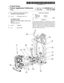
[0010]FIG. 1 is a perspective view of a preferred embodiment of the invention;
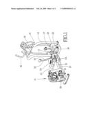
[0011]FIG. 2 is a side view of the embodiment of FIG. 1; and
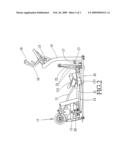
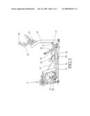
[0012]FIG. 3 is a side view of the embodiment of FIG. 2 after adjustment.
DETAILED DESCRIPTION OF THE PREFERRED EMBODIMENT
[0013]Referring to FIGS. 1 and 2, a preferred embodiment of the invention includes a frame unit 10 und an electric adjusting motor 20.
[0014]The frame unit 10 has a rear end on which a flywheel transmission unit 11 is placed. The flywheel transmission unit includes a crank 12 at both sides thereof that is pivotally coupled to a corresponding treadle plank 13. The elliptical cross trainer has two upright posts 14 at the front end thereof between which a cross bar 15 is extended. Two handles 16 are pivotally attached to the cross bar 15. A bend 17 is pivotally coupled to a bottom end of the handles 16, respectively. Moreover, the opposing end of the bend 17 is pivotally coupled to a bottom end near the front section of the treadle plank 13. In this way, the components are coupled in such a way that they can be synchronically moved.
[0015]The electric adjusting motor 20 is installed at the bottom of the flywheel transmission unit 11 for driving a telescopic tube 21 in a shift movement. The vertical position of the two treadle planks 13 is adjustable by a w-shaped driven by one connecting rod 22 and two L-shaped connecting elements 23.
[0016]As shown in FIGS. 2 and 3, when the telescopic tube 21 is driven by the motor 20 to create a reciprocating in-place displacement thereof, it results in a change of the supporting angle of the w-shaped driven connecting rod 22. In this way, the vertical position of the treadle plank 13 and the treadle 131 thereon can be adjusted by the coupling relationship of the two connecting rods 23. Accordingly, different exercise paces can be achieved.
[0017]Many changes and modifications in the above-described embodiment of the invention can, of course, be carried out without departing from the scope thereof Accordingly, to promote the progress in science and the useful arts, the invention is disclosed and is intended to be limited only by the scope of the appended claim.
Claims:
1. A pace-adjusting mechanism of an elliptical cross trainer,
comprising:a) a frame unit having a rear end on which a flywheel
transmission unit is placed, the flywheel transmission unit including a
crank at both side thereof that is pivotally coupled to a corresponding
treadle plank, the elliptical cross trainer having two upright posts at
the front end thereof between which a cross bar is extended, two handles
being pivotally attached to the cross bar, a bend being pivotally coupled
to a bottom end of the handles, respectively, the opposing end of the
bend being pivotally coupled to a bottom end near the front section of
the treadle plank so that the aforementioned components are coupled in
such a way that they can be synchronically moved, andb) an electric
adjusting motor installed at the bottom of the flywheel transmission unit
for driving a telescopic tube in a shift movement, the vertical position
of the two treadle planks being adjustable by a w-shaped driven by one
connecting rod and two L-shaped connecting elements,whereby, when the
telescopic tube is driven by the motor to create a reciprocating in-place
displacement thereof, it results in a change of the supporting angle of
the w-shaped driven connecting rod such that the vertical position of the
treadle plank and the treadle thereon can be adjusted by the coupling
relationship of the two connecting rods, thereby achieving different
exercise paces.Description:
BACKGROUND OF THE INVENTION
[0001]1. Fields of the Invention
[0002]The invention relates to a pace-adjusting mechanism of an elliptical cross trainer, and more particularly, to a mechanism that can rapidly adjust the movement pace at will.
[0003]2. Description of the Related Art
[0004]The elliptical cross trainer is so used that the operator's feet can make an elliptical movement path, thereby simulating the real running and walking path. Moreover, the horizontal pace (simulating the movement on a flat ground) and the inclined pace (simulating the uphill and downhill movement) can be changed when the vertical position of the treadles of the elliptical cross trainer changes. This is the main intention of the invention.
[0005]U.S. Pat. No. 6,090,013 discloses such a mechanism that employs a plurality of selection holes in treadle planks. By selecting a desired hole in the treadle plank for connection, the coupling angle of the treadle plank can be changed to achieve the above-mentioned pace-adjusting effect.
[0006]In fact, the manual adjustment of the aforementioned prior art is not a practical solution. This is because the operator has to stop the exercise for adjustment of the movement pace, thereby reducing the desire of using the elliptical cross trainer. Meanwhile, this adjustment way must affect the exercise rhythm. Thus, it is hardly possible to use the pace-adjusting mechanism during the exercise sessions so that this kind of the pace-adjusting mechanism is not so practical and valuable as expected.
SUMMARY OF THE INVENTION
[0007]It is a primary object of the invention is to provide a pace-adjusting mechanism of an elliptical cross trainer that employs an electric adjusting mechanism instead of a manual adjusting mechanism. In this way, the operator can easily perform a desired adjustment during the exercise session without stopping the exercise and affecting the movement rhythm. Accordingly, the pace-adjusting mechanism of an elliptical cross trainer can be easily and practically used.
[0008]According to the invention, an electric adjusting motor is employed to drive a telescopic tube for creating a change of the supporting angle of a w-shaped driven connecting rod pivotally coupled to the frame unit. Meanwhile, an L-shaped connecting element pivotally coupled to the treadle plank is employed for adjusting the position of the treadles and changing the movement pace.
BRIEF DESCRIPTION OF THE DRAWINGS
[0009]The accomplishment of this and other objects of the invention will become apparent from the following description and its accompanying drawings of which:
[0010]FIG. 1 is a perspective view of a preferred embodiment of the invention;
[0011]FIG. 2 is a side view of the embodiment of FIG. 1; and
[0012]FIG. 3 is a side view of the embodiment of FIG. 2 after adjustment.
DETAILED DESCRIPTION OF THE PREFERRED EMBODIMENT
[0013]Referring to FIGS. 1 and 2, a preferred embodiment of the invention includes a frame unit 10 und an electric adjusting motor 20.
[0014]The frame unit 10 has a rear end on which a flywheel transmission unit 11 is placed. The flywheel transmission unit includes a crank 12 at both sides thereof that is pivotally coupled to a corresponding treadle plank 13. The elliptical cross trainer has two upright posts 14 at the front end thereof between which a cross bar 15 is extended. Two handles 16 are pivotally attached to the cross bar 15. A bend 17 is pivotally coupled to a bottom end of the handles 16, respectively. Moreover, the opposing end of the bend 17 is pivotally coupled to a bottom end near the front section of the treadle plank 13. In this way, the components are coupled in such a way that they can be synchronically moved.
[0015]The electric adjusting motor 20 is installed at the bottom of the flywheel transmission unit 11 for driving a telescopic tube 21 in a shift movement. The vertical position of the two treadle planks 13 is adjustable by a w-shaped driven by one connecting rod 22 and two L-shaped connecting elements 23.
[0016]As shown in FIGS. 2 and 3, when the telescopic tube 21 is driven by the motor 20 to create a reciprocating in-place displacement thereof, it results in a change of the supporting angle of the w-shaped driven connecting rod 22. In this way, the vertical position of the treadle plank 13 and the treadle 131 thereon can be adjusted by the coupling relationship of the two connecting rods 23. Accordingly, different exercise paces can be achieved.
[0017]Many changes and modifications in the above-described embodiment of the invention can, of course, be carried out without departing from the scope thereof Accordingly, to promote the progress in science and the useful arts, the invention is disclosed and is intended to be limited only by the scope of the appended claim.
User Contributions:
Comment about this patent or add new information about this topic:
| People who visited this patent also read: | |
| Patent application number | Title |
|---|---|
| 20160148261 | SYSTEM FOR CONTEXTUALIZING GEOCODABLE QUERIES |
| 20160148260 | ADVERTISEMENT PROVIDING SYSTEM AND METHOD |
| 20160148259 | METHOD OF MANAGING COOKIE INFORMATION FOR TARGET ADVERTISEMENT AND APPLICATION FOR MANAGING COOKIE INFORMATION |
| 20160148258 | METHOD AND SYSTEM FOR RECOMMENDING A MERCHANT BASED ON TRANSACTION DATA |
| 20160148257 | SYSTEMS AND METHODS FOR RECOMMENDING VACATION OPTIONS BASED ON HISTORICAL VACATION DATA |
Images included with this patent application:
 |  |
 |  |
| Similar patent applications: | |
| Date | Title |
|---|---|
| 2012-09-20 | Method for adjusting the weight-training mass of a weightplate device |
| 2009-11-26 | Free wheel clutch mechanism for bicycle drive train |
| 2012-05-24 | Electric cushioning mechanism of a treadmill |
| 2012-10-25 | Cushioning mechanism for a treadmill |
| 2009-03-12 | Folding mechanism of a treadmill |
| New patent applications in this class: | |
| Date | Title |
|---|---|
| 2016-12-29 | Exercise apparatus |
| 2016-06-09 | Adjustable stride length in an exercise machine |
| 2016-06-02 | Elliptical exercise device with cam drive |
| 2016-06-02 | Elliptical exercise device |
| 2016-06-02 | Elliptical exercise device with cam drive |
| New patent applications from these inventors: | |
| Date | Title |
|---|---|
| 2012-05-31 | Bendable handrail assembly of an exercise apparatus |
| 2012-05-10 | Electric treadmill with a folding mechanism by use of two swivel pieces |
| 2012-02-23 | Lever switch for safe breaking of a circuit of an exercise apparatus |
| 2011-12-15 | Electric treadmill with a folding mechanism by use of a swivel piece |
| Top Inventors for class "Exercise devices" | |
| Rank | Inventor's name |
|---|---|
| 1 | William T. Dalebout |
| 2 | Scott R. Watterson |
| 3 | Raymond Giannelli |
| 4 | Leao Wang |
| 5 | Bruce Hockridge |