Patent application title: Easy in Sand-Brella
Inventors:
Constantine N. Colyvas (Southampton, NY, US)
IPC8 Class: AA45B2300FI
USPC Class:
248545
Class name: Supports with means to facilitate installation, repair, or transportation, or broken parts retainer for ground insertion
Publication date: 2009-02-26
Patent application number: 20090050778
Inventors list |
Agents list |
Assignees list |
List by place |
Classification tree browser |
Top 100 Inventors |
Top 100 Agents |
Top 100 Assignees |
Usenet FAQ Index |
Documents |
Other FAQs |
Patent application title: Easy in Sand-Brella
Inventors:
Constantine N. Colyvas
Agents:
Constantine N. Colyvas
Assignees:
Origin: SOUTHAMPTON, NY US
IPC8 Class: AA45B2300FI
USPC Class:
248545
Abstract:
A device to make the insertion of a beach sun umbrella into the sand
easier and faster, by adding a second piece of metal tube, of slightly
larger diameter than main stem A, about 25 inches in length and placed
over the lower part of the main stem A, like a sleeve. The bottom of this
tube B is cut, to form teeth that will cut the sand, when this tube B is
rotated by a hand held cordless electric motor and secured in place by
the brackets, which also hold tube B secure and cushion (i) of stem A
support A conical gear ring (d) is secured at the top of tube B and a
ring (f) also secured in main stem A, which with the brackets (h), (j)
and (k) hold all the parts in place, for good operation.Claims:
1. A new method of building a beach umbrella, so it will be easier to
install and secure in the sand, comprisinga) a second piece of metal
tube, similar to the umbrella's stem A, but slightly larger in diameter,
about 25 inches long, covering the lower part of the umbrella's stem A,
like a sleeveb) the bottom of this tube B will be cut to form teeth, that
will open the way into the sand when this outer tube B is rotated, as we
will explain laterc) the top of said tube B will be fitted with an
outside conical gear ringd) another ring of adequate thickness will be
secured on tube A, to keep tube B from sliding further up, from its
designated positione) three brackets (h), (j) and (k) attached to ring
(f) will hold said tube B in place brackets (h) and (k) are connected
together at their lower parts, to create a platform, which also has a
hole (o) to hold the cordless motor in positionf) a cordless electric
motor, fitted with a conical gear, proper to mesh and turn the outer tube
B gear ring (d)j) a cushion (i) attached to said tube A, will support the
body of the cordless electric motor and keep it in place, for proper gear
engagement.
2. A cordless electric motor, turning a conical gear proper to mesh and turn, as in claim 1 said tube B that will cut a way into the sand and make easier the insertion and securing of the SB main stem Ah) said cordless electric motor having a pin (g) and gear (n) that will enter hole (o) of platform (l) to keep the gears properly messed, for good operation.
Description:
FIELD OF INVENTION
[0001]This invention relates, as the title states, to a new beach sun umbrella, that its stem is specially modified to allow, even a young person, to easily install and secure in the sand.
DESCRIPTION OF RELATED ART
[0002]All beach umbrellas, that we know of, are made of a metal (usually aluminum) stem, on which the umbrella is added, with no special fictures to assist in inserting the stem into the sand, which often is not easy.
BRIEF SUMMARY OF THE INVENTION
[0003]The extra device, that we have added to our Sand Brella (SB) and will describe hereunder, will eliminate the above defect, by adding a second piece of metal tube B, slightly, larger in diameter than the main stem A, fitted over the lower part of stem A, like a sleeve.
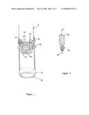
[0004]The bottom of outer tube B (FIG. 1), will be cut to form teeth (p) that will cut the way into the sand, when the tube B is rotated, while pushed down, as we will explain later.
[0005]The top of the external B tube will be fitted with an outside conical gear ring (d). Another ring (f) will be secured on tube A, to keep tube B, from sliding further up, when pushing tube A down, while tube B is rotated, by a hand held cordless electric motor and properly held in place by fittings, as we will explain next.
[0006]Three brackets (h), (j) and (k), attached to ring (f), will hold tube B in place. Additionally brackets (h) and (k), are connected together at their lower parts to form a platform (l), which also has hole (o), for supporting the end pin (g) of the cordless motor gear (n).
[0007]A cushion (i) attached to the tube A, will support the body of the cordless electric motor in place, for proper gear engagement.
DESCRIPTION OF PRIOR ART
[0008]As much as we know, there is no extra facilities, to make the insertion of the umbrella stem into the sand easier, except opening a hole in the sand, with a small shovel and inserting the stem after.
BRIEF DESCRIPTION OF THE DRAWINGS
[0009]FIG. 1, is a front view of the lower part of the Sand Brella stem A, with the additional tube B installed.
[0010]The top of tube B will be fitted with a conical gear ring (d) and secured there
[0011]Another ring (f) will be fitted and secured in tube A, at a place to keep the bottom of tube A slightly higher than the bottom of tube B and to stop tube B, from sliding further up, when pushing tube A down, while tube B is rotated by an electric motor, as we will explain later.
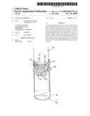
[0012]Three brackets (h), (j) and (k) attached to ring (f), will hold tube B in place, additionally, brackets ((h and (k) are connected together at their lower parts, with platform (l), which also has a hole (o) that will support pin (g) of the electric motor (m) FIG. 2, as we will explain later.
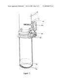
[0013]FIG. 2 is a side view of the cordless electric motor (m), showing the conical gear (n), the pin (g) and the push down switch © that will operate the motor (m).
[0014]FIG. 3 is a view of the entire above described unit, with the cordless electric motor installed in place and pushed against cushion (i), the right place for proper gear engagement.
[0015]The cordless electric motor, will be kept separate from the umbrella, and only put in place and held there by the right hand, pushed against the support cushion (i), while the left hand will grab the stem A, above the motor support and push down, when the right hand thumb will push the electric switch on, to operate the motor, that will cut the sand and allow the main stem A to follow and be installed in there
[0016]After the stem inserting operation is finished, the motor should be pulled off, and kept in a dry and safe place, for next time installment operation.
User Contributions:
comments("1"); ?> comment_form("1"); ?>Inventors list |
Agents list |
Assignees list |
List by place |
Classification tree browser |
Top 100 Inventors |
Top 100 Agents |
Top 100 Assignees |
Usenet FAQ Index |
Documents |
Other FAQs |
User Contributions:
Comment about this patent or add new information about this topic:
Images included with this patent application:
 |  |
 |
| New patent applications in this class: | |
| Date | Title |
|---|---|
| 2015-01-22 | Autonomous remote anchor system |
| 2014-08-21 | Post stabilizer |
| 2013-12-12 | Showmestand tm |
| 2013-11-28 | Card holder |
| 2013-11-07 | Soaker hose securing pin |
| Top Inventors for class "Supports" | |
| Rank | Inventor's name |
|---|---|
| 1 | Jeffrey D. Carnevali |
| 2 | Yun-Lung Chen |
| 3 | Wen-Tang Peng |
| 4 | Zheng-Heng Sun |
| 5 | Zhan-Yang Li |