Patent application title: Round table with removable leaves
Inventors:
Jon Koch (Thomasville, NC, US)
IPC8 Class: AA47B104FI
USPC Class:
108 66
Class name: Plural related horizontal surfaces coplanar extension surface circular segment
Publication date: 2009-02-26
Patent application number: 20090050033
Inventors list |
Agents list |
Assignees list |
List by place |
Classification tree browser |
Top 100 Inventors |
Top 100 Agents |
Top 100 Assignees |
Usenet FAQ Index |
Documents |
Other FAQs |
Patent application title: Round table with removable leaves
Inventors:
Jon Koch
Agents:
GREER, BURNS & CRAIN
Assignees:
Origin: CHICAGO, IL US
IPC8 Class: AA47B104FI
USPC Class:
108 66
Abstract:
A table includes a base, a round top which is hingedly secured to the
base, and a plurality of leaves which extend around the top. The top
includes a side surface which is provided with an inwardly extending
slot. A pair of tabs on each leaf extend into the slot, and locking
devices on the leaves releasably lock adjacent leaves together. The base
is provided with a storage compartment for storing the leaves when the
leaves are removed from the top. A support leg is pivotally secured to
the top and is pivotable between a storage position adjacent the top and
a support position in which the leg engages the base and supports the top
in a raised position.Claims:
1. A table comprising a base and a top which is supported by the base, the
top having a side surface with a slot which extends inwardly from the
side surface, and a plurality of leaves which extend around the side
surface of the top, each of the leaves including first and second ends
and inner and outer surfaces, the inner surface of each of the leaves
being positioned adjacent the side surface of the top, the first end of
each of the leaves being positioned adjacent the second end of an
adjacent leaf, a tab on each of the leaves which extends inwardly into
the slot in the side surface of the top, and first and second locking
devices on each of the leaves adjacent the first and second ends thereof,
each of the first locking devices on each of the leaves engaging a second
locking device on an adjacent leaf whereby the leaves are releasably
locked together.
2. The table of claim 1 in which the side surface of the top has a single slot which extends continuously around the side surface.
3. The table of claim 1 in which the side surface of the top is round and each of the leaves is curved.
4. The table of claim 1 including a pair of tabs on each of the leaves which extend inwardly into the slot in the side surface of the top.
5. The table of claim 1 in which each of the leaves includes a projection on the first end thereof and a recess in the second end thereof, the projection on each leaf extending into a recess in the adjacent leaf.
6. The table of claim 1 in which the side surface is round and each of the leaves is curved and the side surface of the top has a single slot which extends continuously around the side surface, and including a pair of tabs on each of the leaves which extend inwardly into the slot in the side surface of the top.
7. The table of claim 6 in which each of the leaves includes a projection on the first end thereof and a recess in the second end thereof, the projection on each leaf extending into a recess in the adjacent leaf.
8. The table of claim 1 in which the top includes a top panel and a bottom panel and the slot is provided by a recess in the bottom panel.
9. The table of claim 1 in which the top is hingedly secured to the base and the base is provided with a storage compartment for storing the leaves.
10. The table of claim 9 including a support rack in the storage compartment for supporting the leaves.
11. The table of claim 10 in which the support rack is provided with a plurality of recesses for receiving the leaves.
12. The table of claim 9 including a support leg pivotally secured to the top which is pivotable between a storage position adjacent the top and a support position in which the leg engages the base and supports the top in a raised position.
13. The table of claim 12 in which the base is provided with a notch for receiving and supporting the leg when the top is in the open position.
14. The table of claim 9 including first and second locking devices on the base and on the top, respectively, which are releasably engageable for locking the top against the base.
15. The table of claim 1 in which the top is hingedly secured to the base and the base is provided with a storage compartment for storing the leaves, a support rack in the storage compartment for supporting the leaves, the support rack being provided with a plurality of recesses for receiving the leaves, and a support leg pivotally secured to the top which is pivotable between a storage position adjacent the top and a support position in which the leg engages the base and supports the top in a raised position.
16. The table of claim 15 in which the base is provided with a notch for receiving and supporting the leg when the top is in the open position.
17. The table of claim 16 including first and second locking devices on the base and on the top, respectively, which are releasably engageable for locking the top against the base.
18. A table comprising a base, a top which is hingedly secured to the base and having a side surface, and a plurality of leaves which extend around the side surface of the top, the base having a storage compartment for storing the leaves, a support rack in the storage compartment for supporting the leaves, and a support leg pivotally secured to the top which is pivotable between a storage position adjacent the top and a support position in which the leg engages the base and supports the top in a raised position.
19. The table of claim 18 in which the base is provided with a notch for receiving and supporting the leg when the top is in the open position.
20. The table of claim 18 which the support rack is provided with a plurality of recesses for receiving the leaves.
21. The table of claim 18 including first and second locking devices on the base and on the top, respectively, which are releasably engageable for locking the top against the base.
Description:
BACKGROUND
[0001]This invention relates to a round table with removable leaves. More particularly, the invention relates to a round table on which the leaves can be supported by the table anywhere around the periphery of the table and which includes a storage compartment for storing the leaves.
[0002]Many tables include removable leaves for increasing the top surface of the table. However, the leaves and the table are generally provided with mounting and/or locking mechanisms which require the leaves to be positioned at particular locations around the table.
[0003]The following United States patents describe round tables with removable or extendible leaves: U.S. Pat. Nos. 254,388; 535,212; 809,703; 894,049; 991,875; 993,517; 993,539; 1,019,826; 1,079,099; 1,158,125; 1,167,461; 1,328,243; 1,406,116; 1,940,201; 2,703,740; 3,636,891; and 4,872,764. However, the leaves cannot be positioned at any desired location around the periphery of the table.
[0004]Some tables are provided with a storage compartment for storing the leaves when they are not in use. However, the storage compartments are generally not accessible from the top of the table, and the process of storing the leaves can be complicated.
[0005]The following United States patents describe tables with a storage compartment for storing the leaves: U.S. Pat. Nos. 535,212; 809,703; 894,049; 993,517; 991,875; 993,539; 1,019,826; 1,079,099; 1,940,201; and 2,703,740.
[0006]U.S. Pat. No. 535,212 does describe a storage compartment which is accessible from the top of the table. However, the compartment is provided by a box-like structure which is supported from the table, and access to the compartment is provided by hinging a central part of the table top to the remainder of the table top.
SUMMARY OF THE INVENTION
[0007]The invention provides a round table with removable curved leaves which can be positioned on the table anywhere around the periphery of the table. The round side surface of the table top is provided with a continuous slot. Two radially inwardly extending tabs on each leaf can be inserted into the slot in the table top for supporting the leaf. One end of each leaf is provided with a recess, and the other end includes a projection which is inserted into the recess of the adjacent leaf. A locking mechanism is mounted adjacent each end of each leaf for locking the leaves together around the table top.
[0008]The table top is hingedly secured to the base of the table, and the base is provided with a storage compartment for the leaves. Access to the storage compartment is provided by lifting the table top, and the top can be supported in the raised position by a support leg which is pivotally secured to the bottom surface of the top. A support rack in the storage compartment is provided with notches or recesses for supporting the leaves.
DESCRIPTION OF THE DRAWING
[0009]The invention will be explained in conjunction with an illustrative embodiment shown in the accompanying drawing, in which:
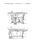
[0010]FIG. 1 is a perspective view of a round table which is formed in accordance with the invention;
[0011]FIG. 2 is fragmentary perspective view of the table top and base;
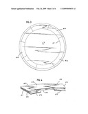
[0012]FIG. 3 is a top view of the table of FIG. 1 with leaves mounted around the periphery of the table;
[0013]FIG. 4 is a top perspective view of one of the leaves;
[0014]FIG. 5 is a bottom perspective view of one of the leaves;
[0015]FIG. 6 is a fragmentary bottom perspective view showing the tabs of one of the leaves being inserted into the slot in the table top;
[0016]FIG. 7 is fragmentary bottom view of a pair of leaves locked together around the table top;
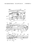
[0017]FIG. 8 is a fragmentary side perspective view of one of the leaves and the table top;
[0018]FIG. 9 is a fragmentary sectional view taken along the line 9-9 of FIG. 8;
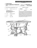
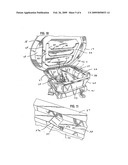
[0019]FIG. 10 is a perspective view of the table top raised to open the storage compartment for the leaves;
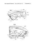
[0020]FIG. 11 is a fragmentary perspective view of one of the notches in the base for supporting the support leg; and
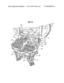
[0021]FIG. 12 is a fragmentary perspective view showing the table top supported in the raised position.
DESCRIPTION OF SPECIFIC EMBODIMENT
[0022]Referring to FIG. 1, a table 15 includes a base 16 and a top 17. As can be seen in FIG. 3, the preferred top 17 is circular and includes a circular periphery or side surface 18. However, the invention can also be used with table tops having other shapes, e.g., rectangular.
[0023]The base 16 includes a chest-like body 20 which is supported by four legs 21. A four-armed stretcher 22 extends below each of the legs, and each of the four arms of the stretcher is supported by a pad or foot 23.
[0024]Referring to FIGS. 10 and 12, the top 17 is pivotally secured to the base 16 by a hinge 25. The interior of the body 20 of the base provides a storage compartment 26 which is opened when the top is raised. The top edge 27 of the body supports the table top when the top is closed.
[0025]A generally rectangular frame 28 is secured to the bottom surface 29 of the table top, and a support leg 30 is pivotally secured to the frame 28. When the support leg is not in use, it lies against the bottom surface of the top as illustrated in FIG. 10. The support leg is advantageously maintained in the storage position against the top by friction between the support leg and the frame 28. When the support leg is pivoted downwardly as shown in FIG. 12, the support leg engages the body 20 and supports the top in a raised or open position.
[0026]The support leg 30 includes a pair of side struts 32 and 33 which are connected and reinforced by cross beams 34 and 35. The upper end of each strut is pivotally connected to the frame 28 by a pin. The cross beam 35 may be provided with a finger notch or recess 36 for assisting in grasping the cross beam and pivoting the support leg away from the table top.
[0027]The bottom end of each of the side struts 32 and 33 is engageable with a notch or recess 37 (FIG. 11) in the body 20 which holds the strut and the top in the open position. Each notch 37 is provided in a fore-and-aft rail 38 which is secured to the body 20 within the storage compartment. The notch is defined by an inclined surface 37a on the rail 38 and a generally vertically extending stop surface or shoulder 37b.
[0028]The table top may be latched in the closed position of FIG. 1 by a conventional rotatable sash lock 40 (FIG. 2) on the body 20 which engages a conventional catch on the top.
[0029]Referring to FIG. 3, the useable surface area of the table top 17 can be increased by mounting a plurality of leaves 44 around the periphery of the table top. In the preferred embodiment of the invention, the table top is round and the leaves are curved. However, other shapes can be used for the top and the leaves.
[0030]Referring to FIGS. 4 and 5, each leaf 44 includes top and bottom surfaces 45 and 46, curved inside and outside edges 47 and 48, and straight end edges 49 and 50. The end edge 49 includes a projection or tenon 51 and the end edge 50 is provided with a pocket or recess 52 (FIG. 8). The projection 51 of each leaf is sized to fit relatively snugly in the pocket 52 of the adjacent leaf. Two tabs or tongues 54 and 55 are secured to the bottom surface of the leaf and extend beyond the inside edge 47. The tabs are preferably made of metal and are attached to the leaf by screws 56 (FIG. 9).
[0031]A conventional sash lock 57 is secured to the bottom surface of the leaf adjacent the end edge 50, and a conventional catch 58 is secured to the bottom surface adjacent the end edge 49. As will be explained more fully hereinafter, each sash lock 57 is adapted to engage the catch 58 on an adjacent leaf when the leaves are mounted on the table top for locking the leaves together.
[0032]A slot 60 (FIGS. 2, 6, 7, and 9) is provided in the side surface 18 of the table top 17. Referring to FIGS. 6 and 9, the leaves 44 are mounted on the table top by inserting the tabs 54 and 55 on the leaves into the slot 60 in the table top. The slot is advantageously sized to receive the tabs relatively snugly so that the leaves are supported in a substantially horizontal position. In the preferred embodiment, the slot 60 extends continuously around the table top, and the tabs can be inserted anywhere around the periphery of the table top. However, the slot can also be provided by a series of discrete slots which are located at various positions around the periphery of the table top.
[0033]The particular table top 17 illustrated in the drawings includes a beveled side surface or nose 61 above the slot 60 (FIGS. 1, 3, 8 and 9). The inside edge 47 of each leaf includes a mating curved surface 62 (FIGS. 8 and 9) which extends over the nose 61 and provides further support for the leaf.
[0034]As additional leaves are mounted on the table top, the end projection 51 on each leaf is inserted into the end pocket 52 of the adjacent leaf. The sash lock 57 of each leaf is actuated to engage the catch 58 of the adjacent leaf to pull the two leaves tightly together. When all of the leaves are locked together, the leaves are drawn firmly against the side surface 18 of the table top. The leaves are thereby securely supported on the table top. The end edges 49 and 50 of the leaves extend radially outwardly from the center of the table top.
[0035]Referring to FIG. 9, in the particular embodiment illustrated in the drawing, the table top 17 includes a top panel 64 and a bottom panel or under frame 65 which is attached to the top panel by screws 66. The under frame 65 is provided with a notch or recess 67 around the entire periphery of the under frame which provides the slot 60 between the top panel 64 and the under frame 65. The recess 67 is machined to close tolerances relative to the thickness of the tabs 54 and 55 so that the tabs are firmly supported in a horizontal position parallel to the top panel 64 and the under frame 65. The outer edge 68 of the under frame terminates inwardly of the nose 61 of the top panel so that the nose conceals the slot 60 when viewed from above the table.
[0036]Alternatively, the slot 60 could be provided by a recess in the top panel 64 or a recess in both the top panel 64 and the bottom panel 65.
[0037]When the leaves are no longer needed, they can be dismounted from the table top and stored within the storage compartment 26 in the base 16. Referring to FIGS. 10 and 12, the body 20 of the base 16 includes four side walls 70, 71, 72, and 73 and a bottom wall (not shown). A pair of support racks 74 are supported by the bottom wall of the body 20 and extend between the side walls 66 and 68. Each support rack is provided with a plurality of notches or slots 75 which are separated by upwardly extending projections 76. The support racks are advantageously covered with felt or other soft material which will not scratch the leaves.
[0038]Each leaf can be inserted into a pair of aligned slots 75 in the two racks 74, and the leaf is held in a generally vertical position by the projections 76. A rib 77 on each of the side walls 71 and 72 engages the ends of the leaf and provides further support for the leaf. The particular table illustrated in the drawings includes eight leaves, and the support racks 74 are provided with eight slots 75.
[0039]After the leaves are positioned in the storage compartment, the table top is raised to remove the support leg 30 from the notches 37 in the base, and the support leg is pivoted upwardly against the bottom surface of the table top. The table top is then lowered against the top surface of the base and locked by the sash lock 40.
[0040]The invention is particularly suitable for use with dining tables, and the embodiment illustrated in the drawings is a dining table. However, the invention can also be used with other types of tables.
[0041]While the foregoing specification provides a detailed description of a specific embodiment for the purpose of illustration, it will be understood that many of the details described herein can be varied considerably by those skilled in the art without departing from the spirit and scope of the invention.
User Contributions:
comments("1"); ?> comment_form("1"); ?>Inventors list |
Agents list |
Assignees list |
List by place |
Classification tree browser |
Top 100 Inventors |
Top 100 Agents |
Top 100 Assignees |
Usenet FAQ Index |
Documents |
Other FAQs |
User Contributions:
Comment about this patent or add new information about this topic:
| People who visited this patent also read: | |
| Patent application number | Title |
|---|---|
| 20140094043 | HEADER CONNECTOR |
| 20140094042 | POWER SUPPLY SYSTEM INCLUDING PANEL WITH SAFETY RELEASE |
| 20140094041 | CONTACT SYSTEM |
| 20140094040 | PLASMA PROCESSING METHOD |
| 20140094039 | EDGE RING LIP |
Images included with this patent application:
 |  |
 |  |
 |  |
 |
| Similar patent applications: | |
| Date | Title |
|---|---|
| 2011-07-14 | Device for mounting a table top on a frame with drive means |
| 2012-04-12 | Veterinary table assembly with rotatable table |
| 2009-04-23 | Multimedia table with rotatable tray |
| 2010-12-30 | Aircraft table system with retractable support bolts |
| 2010-07-29 | Folding table with crossed legs |
| New patent applications in this class: | |
| Date | Title |
|---|---|
| 2009-02-26 | Expandable table and center alignment assembly for such an expandable table |
| Top Inventors for class "Horizontally supported planar surfaces" | |
| Rank | Inventor's name |
|---|---|
| 1 | Mitch Johnson |
| 2 | Wendell Peery |
| 3 | David C. Winter |
| 4 | William P. Apps |
| 5 | Mustafa A. Ergun |