Patent application title: DISCHARGE CONTROL SYSTEM
Inventors:
Derick Ivany (Ottawa, CA)
Kim King (San Antonio, TX, US)
IPC8 Class: AF42B3300FI
USPC Class:
86 50
Class name: Ammunition and explosive-charge making bomb disposal
Publication date: 2009-02-19
Patent application number: 20090044692
Inventors list |
Agents list |
Assignees list |
List by place |
Classification tree browser |
Top 100 Inventors |
Top 100 Agents |
Top 100 Assignees |
Usenet FAQ Index |
Documents |
Other FAQs |
Patent application title: DISCHARGE CONTROL SYSTEM
Inventors:
Derick Ivany
Kim King
Agents:
ECKERT SEAMANS CHERIN & MELLOTT
Assignees:
Origin: PITTSBURGH, PA US
IPC8 Class: AF42B3300FI
USPC Class:
86 50
Abstract:
The invention generally relates to a discharge control system that is
structured to destroy objects having a charge such as ammunition,
explosives and/or pyrotechnic objects and control the discharge of the
charges. The discharge control system has a closable control vessel that
is structured to receive a number of objects therein with some of the
objects having a charge. A heat source is coupled to the closable control
vessel and a filter system is coupled to the closable control vessel. The
heat source is structured to supply heat to the number of objects. An
effective amount of heat discharges the number of objects that have a
charge and the filter system is structured to collect particulate matter
released from the discharged objects. The heat source may be a radiant
heat source. The filter system may be provided with an air filter that is
a high efficiency particulate air filter.Claims:
1. A discharge control system comprising:a closable control vessel
structured to receive a number of objects therein with at least some of
the objects having a charge;a heat source coupled to the closable control
vessel; anda filter system coupled to the closable control vessel,wherein
the heat source is a radiant heat source,wherein the heat source is
structured to supply heat to the number of objects,wherein an effective
amount of heat discharges the number of objects that have a charge,
andwherein the filter system is structured to collect particulate matter
released from the discharged objects.
2. The discharge control system of claim 1 wherein the radiant heat source is selected from the group consisting of an electric supply and propane.
3. The discharge control system of claim 2 wherein the electric supply is generated by a generator.
4. The discharge control system of claim 1 further comprising a gas source coupled to the closable control vessel wherein the gas source is structured to move a gas into the closable control vessel to move particulate matter into the filter system.
5. The discharge control system of claim 1 wherein the filter system is provided with an air filter and wherein the air filter is a high efficiency particulate air filter.
6. The discharge control system of claim 1 wherein the closable control vessel has an opening.
7. The discharge control vessel of claim 6 wherein the opening has a portion thereof structured to be closed by a plate.
8. The discharge control vessel of claim 6 wherein the opening has a portion thereof structured to be closed by a door.
9. The discharge control vessel of claim 8 further comprising:a number of vertical risers coupled to the closable control vessel; anda horizontal bar pivotally coupled to the number of vertical risers,wherein the door is slidably movable relative to the horizontal bar.
10. The discharge control vessel of claim 9 further comprising a number of biasing members provided around the horizontal bar and coupled to the door.
11. The discharge control vessel of claim 8 wherein application of a force in a general upward direction on the door when the door is in a closed position releases the door from a bracket and allows the door to slide from the opening toward an open position.
12. The discharge control vessel of claim 8 wherein application of a force in a general downward direction on the door when the door is in an open position slides the door toward the opening to secure the door in a closed position.
13. The discharge control system of claim 1 wherein the closable control vessel is coupled to a frame.
14. The discharge control system of clam 13 wherein the frame is placed on a trailer.
15. The discharge control system of claim 13 wherein an enclosure is provided within the frame and wherein the enclosure has an enclosure door that is structured to provide access to a region within the enclosure.
16. The discharge control system of claim 15 further comprising a container placed within the enclosure structured to collect substances from the closable control vessel after discharge of the number of objects having a charge.
17. The discharge control system of claim 16 further comprising a tray provided within the closable control vessel which is structured to receive the number of objects.
18. The discharge control system of claim 17 further comprising a funnel provided under the tray wherein the funnel is structured to receive substances and move the substances toward the container.
19. A discharge control system comprising:a closable control vessel structured to receive a number of objects therein with at least some of the objects having a charge;a heat source coupled to the closable control vessel; anda filter system coupled to the closable control vessel,wherein the filter system is provided with an air filter,wherein the air filter is a high efficiency particulate air filter,wherein the heat source is structured to supply heat to the number of objects,wherein an effective amount of heat discharges the number of objects that have a charge, andwherein the filter system is structured to collect particulate matter released from the discharged objects.
20. The discharge control system of claim 19 wherein the heat source is a radiant heat source.
21. The discharge control system of claim 20 wherein the radiant heat source is selected from the group consisting of an electric supply and propane.
22. The discharge control system of claim 21 wherein the electric supply is generated by a generator.
23. The discharge control system of claim 19 further comprising a gas source coupled to the closable control vessel wherein the gas source is structured to move a gas into the closable control vessel to move particulate matter into the filter system.
24. The discharge control system of claim 19 wherein the closable control vessel has an opening.
25. The discharge control vessel of claim 24 wherein the opening has a portion thereof structured to be closed by a plate.
26. The discharge control vessel of claim 24 wherein the opening has a portion thereof structured to be closed by a door.
27. The discharge control vessel of claim 26 further comprising:a number of vertical risers coupled to the closable control vessel; anda horizontal bar pivotally coupled to the number of vertical risers,wherein the door is movable relative to the horizontal bar.
28. The discharge control vessel of claim 27 further comprising a number of biasing members provided around the horizontal bar and coupled to the door.
29. The discharge control vessel of claim 26 wherein application of a force in a general upward direction on the door when the door is in a closed position releases the door from a bracket and allows the door to slide from the opening toward an open position.
30. The discharge control vessel of claim 26 wherein application of a force in a general downward direction on the door when the door is in an open position slides the door toward the opening to secure the door in a closed position.
31. The discharge control system of claim 19 wherein the closable control vessel is coupled to a frame.
32. The discharge control system of claim 31 wherein the frame is placed on a trailer.
33. The discharge control system of claim 31 wherein an enclosure is provided within the frame and wherein the enclosure has an enclosure door that is structured to provide access to a region within the enclosure.
34. The discharge control system of claim 33 further comprising a container placed within the enclosure structured to collect substances from the closable control vessel after discharge of the number of objects having a charge.
35. The discharge control system of claim 34 further comprising a tray provided within the closable control vessel which is structured to receive the number of objects.
36. The discharge control system of claim 35 further comprising a funnel provided under the tray wherein the funnel is structured to receive substances and move the substances toward the container.
Description:
PARENT CASE TEXT
[0001]This patent application claims priority under 35 U.S.C. § 119(e)(1) to provisional patent application No. 60/956,003 filed Aug. 15, 2007, the contents of which are hereby incorporated by reference into this patent application in its entirety as if fully set forth herein.
FIELD OF THE INVENTION
[0002]The invention generally relates to a discharge control system. More particularly, the discharge control system is structured to destroy objects having a charge such as ammunition, explosives and/or pyrotechnic objects and control the discharge of the charges provided in such objects.
BACKGROUND INFORMATION
[0003]A discharge control system is typically used by law enforcement personnel, bomb squads, etc. to safely destroy or discharge confiscated ammunition, explosives and/or pyrotechnic objects. In the prior art, such objects would simply be burned. Due to increased environmental regulations, such an approach is no longer a desirable option.
[0004]A problem that exists with certain prior art discharge control systems is that the systems use a flame burner for destroying an object having a charge in the discharge control system. The problem with the flame destruction method is that it is not a clean process and undesired byproducts result from burning the objects with a flame. Flame burning the object having a charge is not an environmentally desirable process.
[0005]Another problem that exists with certain prior art discharge control systems is that the systems do not have environmentally desirable filter systems that scrub particulate emissions from ammunition, explosives and/or pyrotechnic objects that are destroyed in a vessel.
[0006]Accordingly, there is room for improvement in discharge control systems.
SUMMARY OF THE INVENTION
[0007]An object of the invention is to provide a discharge control system that uses a heat source for destroying an object having a charge in a cleaner process that reduces the amount of undesired byproducts emitted from spent charges.
[0008]Another object of the invention is to provide a discharge control system that has a filter system that scrubs particulate emissions from ammunition, explosives and/or pyrotechnic objects that are destroyed in a vessel.
[0009]Certain objects of the invention are achieved by providing a discharge control system that has a closable control vessel structured to receive a number of objects therein. At least some of the objects have a charge. A heat source is coupled to the closable control vessel and a filter system is coupled to the closable control vessel. The heat source is a radiant heat source and is structured to supply heat to the number of objects. An effective amount of heat discharges the number of objects that have a charge and the filter system is structured to collect particulate matter released from the discharged objects.
[0010]Other objects of the invention are achieved by providing a discharge control system that has a closable control vessel structured to receive a number of objects therein. At least some of the objects have a charge. A heat source is coupled to the closable control vessel and a filter system is coupled to the closable control vessel. The filter system is provided with an air filter. The air filter is a high efficiency particulate air filter. The heat source is structured to supply heat to the number of objects. An effective amount of heat discharges the number of objects that have a charge and the filter system is structured to collect particulate matter released from the discharged objects.
BRIEF DESCRIPTION OF THE DRAWINGS
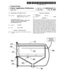
[0011]FIG. 1 is an end view of a discharge control system in accordance with an embodiment of the invention;
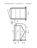
[0012]FIG. 2 is a side view of the discharge control system shown in FIG. 1;
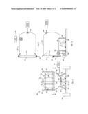
[0013]FIG. 3 is a top view of the discharge control system shown in FIG. 1;
[0014]FIG. 4 is a side cross-sectional view taken along section A-A of the discharge control system shown in FIG. 1; and
[0015]FIG. 5 is a side cross-sectional view taken along section B-B of the discharge control system shown in FIG. 1
DETAILED DESCRIPTION OF THE PREFERRED EMBODIMENTS
[0016]For purposes of the description hereinafter, the terms "upper", "lower", "vertical", "horizontal", "axial", "top", "bottom", "aft", "behind", and derivatives thereof shall relate to the invention as it is oriented: (i) in the drawing FIGS.; (ii) when resting upright on a flat horizontal surface; or (iii) when provided on a trailer placed on a flat horizontal surface. However, it is to be understood that the invention may assume various alternative configurations when the invention is moved about or is placed in a non-upright position. It is also to be understood that the specific elements illustrated in the FIGS. and described in the following specification are simply exemplary embodiments of the invention. Therefore, specific dimensions, orientations and other physical characteristics related to the embodiments disclosed herein are not to be considered limiting.
[0017]As employed herein, the term "number" shall mean one or an integer greater than one (i.e., a plurality). As employed herein, the statement that two or more parts are "attached", "connected", "coupled", or "engaged" together shall mean that the parts are joined together either directly or joined through one or more intermediate parts.
[0018]Turning to FIGS. 1-2, a discharge control system 10 of the invention is shown. The discharge control system 10 may be used for safely destroying or discharging a number of objects that have a charge such as certain types of ammunition, explosives and/or pyrotechnic objects, for example. The discharge control system 10 controls the charge released from such objects when the objects are thermally destroyed or exploded. The discharge control system 10 has a closable control vessel 12.
[0019]In the depicted embodiment, the closable control vessel 12 has an opening 14 that has a portion thereof structured to be closed by a plate 16 coupled to a face of the closable control vessel 12 with fasteners, weldments or the like. Another portion of the opening is structured to be closed by a door 18. The door 18 is preferably slidably movable relative to a horizontal bar 20 in a vertical direction between a number of vertical risers 22 that are coupled to the closable control vessel 12 with fasteners, weldments or the like. The vertical risers 22 may be reinforced with a number of reinforcement members. A number of biasing members 24 are provided along the horizontal bar 20 and are coupled to the door 18.
[0020]If an end-user of the discharge control system 10 applies force in a general upward direction on the door 18 when the door 18 is in a closed position, the door 18 is released from a bracket 26 and the door 18 is free to slide upward from the opening 14 toward an open position (not shown). As the door 18 slides upward, the biasing members 24 provided along the door 18 assist in lifting the door 18. The end-user is provided with access to the opening 14 in order to load a number of objects having a charge that are to be destroyed within the closable control vessel 12.
[0021]If an end-user of the discharge control system 10 applies force in a general downward direction on the door 18 when the door 18 is in the open position, the door 18 will slide downward toward the opening 14 toward the closed position. As the door 18 slides downward, the biasing members 24 generally counteract the weight of the door. When the door 18 closes the opening 14 of the closable control vessel 12 by moving the door 18 downward, the door 18 may be secured in such a closed position by capturing an end of the door 18 with the bracket 26. When the door 18 is closed, the discharge control system 10 is ready to destroy the number of objects having a charge that were loaded within the closable control vessel 12 as is described in greater detail below. While the embodiment described in detail herein includes a slidable door of particular design, it is to be appreciated that other suitable mechanisms providing access to the interior of the vessel 12 may be employed.
[0022]With reference to FIG. 1, the closeable control vessel 12 is coupled to a frame 28 that is structured to be placed on a surface (not shown). In the depicted embodiment, the frame 28 is shown placed on a trailer 30 (shown schematically) that may be moved about with a motorized vehicle or the like. As can be appreciated, the frame 28 may be placed on an elongated bed of a truck or other surfaces such as, for example, a floor.
[0023]Within the frame 28, an enclosure 32 may be provided. An end-user may access a region within the enclosure 32 by opening an enclosure door 34. A container 36 may be placed within the enclosure 32. The container 36 is structured to collect substances such as liquids and solids, for example, from the closable control vessel 12 after the destruction or discharge of the number of objects having a charge. The closable control vessel 12 has an enclosure inlet port 38 for moving substances such as liquids and solids, for example, from the closable control vessel 12 to the enclosure 32.
[0024]When the door 18 is in the open position, the end-user would place a number of objects having a charge such as ammunition, explosives and/or pyrotechnic objects, for example, on a tray 40 provided within the closable control vessel 12 such as shown in FIGS. 4 and 5. Once the end-user has placed the objects having a charge for destruction or discharge on the tray 40 provided within the closable control vessel 12, the end-user moves the door 18 to the closed position prior to initiating the process of destroying or discharging the objects with a heat source 42 as will be discussed below.
[0025]As shown in FIG. 4, the heat source 42 is coupled to the closable control vessel 12 by a heat inlet port 44 provided in the closable control vessel 12. In the embodiment shown, the heat source 42 is shown as a heating element within the closable control vessel 12. In alternate embodiments, the heat source 42 could be provided external to the closable control vessel 12. The heat source 42 may be a radiant heat source which produces a cleaner internal burn within the closable control vessel 12 than flame burners used in the prior art. As shown, the radiant heat may be supplied from an electric supply, although propane or other radiant heat sources may also be employed. The electric supply could also be generated, for example, by a generator that is located on the trailer 30. The heat source 42 is structured to supply heat to the number of objects provided within the closable vessel 12. An effective amount of heat discharges the number of objects that have a charge.
[0026]In the embodiment of the invention as shown in FIGS. 4 and 5, the inside of the closable control vessel 12 is lined with a layer of insulation 43 and an internal shell 45. The layer of insulation may preferably be a ceramic blanket type insulation, however other suitable materials may be employed. The internal shell 45 is preferably made from a stainless steel, however other suitable materials may be employed. The internal shell 45 prevents the insulation from being exposed to the inside environment during the discharge process. The internal shell 45 completely covers the inside of the vessel and consists of an internal door 47 that also is either preferably constructed from, or contains insulating material. The insulation is provided to reduce the power required to attain the desired temperature along with preventing the outside of the vessel 12 from becoming dangerously hot.
[0027]In the prior art, heat sources were typically flame burners that supplied an internal flame to the charges to be destroyed or discharged within the control vessel. The problem with the flame destruction method is that it is not a clean process and undesired byproducts result from burning the charges with the flame. Flame burning charges is not an environmentally desirable process.
[0028]A filter system 46 (shown schematically in FIGS. 1 & 2) is coupled to the closable control vessel 12 by a filter exhaust port 48. The filter system 46 is structured to collect particulate matter released from the spent charges or discharged objects. A gas source 50 (shown schematically in FIG. 3) is also coupled to the closable control vessel 12 by a gas source inlet port 52. The gas source 50 is structured to selectively move gas such as air, for example, into the closable control vessel 12 to move particulate matter into the filter system 46. Although not shown in the FIGS., it is to be appreciated that at least one inlet port and one outlet port is provided through the insulation 43 and internal shell 45 to allow inflow and exhaust from with the internal shell 45.
[0029]Once the number of objects having a charge placed on the tray 40 have been discharged or exploded with an effective amount of heat from the heat source 42, the particulate matter released from the spent charges are collected by the filter system 46. The filter system 46 of the invention advantageously eliminates harmful pollutants from being expelled from the discharge control system 10 into the environment. The released particulate matter is moved from the closable control vessel 12 into the filter system 46 by the gas source 50 coupled to the closable control vessel 12. The gas source 50 supplies air, for example, to the closable control vessel 12 to move the particulate matter from the destroyed charges into the filter system 46.
[0030]The filter system 46 is provided with an air filter. The air filter could be a high efficiency particulate air ("HEPA") filter. HEPA filters typically remove at least 99.97% of airborne particles that are approximately 0.3 micrometers in diameter. Particles that are larger or smaller than 0.3 micrometers are typically also filtered by a HEPA filter. Preferably, filter system 46 also includes a vapor filter.
[0031]In the prior art, filter systems, if used at all, did not scrub the particulate matter discharge released from ammunition, explosives and/or pyrotechnic objects that were destroyed or discharged in a discharge control system. As such, harmful pollutants were often a byproduct of such prior art discharge control systems. The problem with not using filter systems coupled to a discharge control system or not using filter systems fitted with a HEPA filter is that such an approach is not a clean process and undesired emissions from the discharge control system result from destroying the charges.
[0032]Once the number of objects having a charge placed on the tray 40 have been discharged or exploded with heat from the heat source 42, the tray 40 also collects any brass casings associated with the objects since the temperature within the closable control vessel 12 does not reach the melting temperature of brass. After the charges have been destroyed, the heat source 42 may be turned off, the door 18 opened and the tray 40 removed from the closeable control vessel 12 in order to retrieve the spent brass casings which may be salvaged for the metal content.
[0033]Also, once the number of objects having a charge placed on the tray 40 have been discharged or exploded with the heat source 42, the tray 40 may also collect any lead associated with the objects if the temperature within the closable control vessel 12 is controlled so the temperature does not reach the melting temperature of lead. Like the brass casings, after the charges have been destroyed, the heat source 42 may be turned off, the door 18 opened and the tray 40 removed from the closeable control vessel 12 in order to retrieve any lead which may be salvaged for the metal content.
[0034]Alternatively, the temperature of the heat source 42 provided within the closable control vessel 12 may be placed at a level to discharge or explode the objects having a charge placed on the tray 40 and at a level that effectively melts any lead, but not any brass provided in the spent objects. In such a case, after the charges have been destroyed, the heat source 42 may be turned off, the door 18 opened and the tray 40 removed from the closeable control vessel 12 in order to retrieve any brass which may be salvaged for the metal content.
[0035]As shown in FIG. 4, a funnel or equivalent structure (not numbered) may be provided under the tray 40. The funnel or equivalent structure is structured to receive substances such as molten lead, for example, from the tray 40 and move the substances by gravity through the enclosure inlet port 38 toward the container 36 placed within the enclosure 32. The enclosure 32 beneficially contains any harmful lead vapors that may be provided in the enclosure 32. Once the lead solidifies, the enclosure door 34 may be opened and the container 36 removed from the enclosure 32 in order to retrieve any lead which may be salvaged for the metal content.
[0036]The discharge control system 10 is capable of discharging up to 150 pounds (68.04 kg) of 50 caliber (12.7 mm) or less ammunition. In the event the discharge of the charge becomes unstable, the discharge control system 10 can control the effects of a high order explosion of up to 1.5 pounds (0.680 kg) of trinitrotoluene (TNT) or its equivalent. The discharge control system 10 may weigh less than 7000 pounds (3175 kg) which allows the discharge control system 10 to be towed by many types of vehicles.
[0037]While specific embodiments of the invention have been described in detail, it will be appreciated by those skilled in the art that various modifications and alternatives to those details could be developed in light of the overall teachings of the disclosure. Accordingly, the particular arrangements disclosed are meant to be illustrative only and not limiting as to the scope of the invention which is to be given the full breadth of the claims appended hereto and any and all equivalents thereto.
User Contributions:
comments("1"); ?> comment_form("1"); ?>Inventors list |
Agents list |
Assignees list |
List by place |
Classification tree browser |
Top 100 Inventors |
Top 100 Agents |
Top 100 Assignees |
Usenet FAQ Index |
Documents |
Other FAQs |
User Contributions:
Comment about this patent or add new information about this topic:
Images included with this patent application:
 |  |
 |
| Similar patent applications: | |
| Date | Title |
|---|---|
| 2013-08-08 | Attachment/release device and assemblies and systems using same |
| 2013-07-25 | Packaging machines suitable for shot bags and related methods |
| New patent applications in this class: | |
| Date | Title |
|---|---|
| 2022-05-05 | Mobile ordnance disposal system |
| 2016-06-16 | Gas compensated recoilless liquid disrupter |
| 2016-02-25 | Thermal destruction arrangement |
| 2015-02-12 | Pyrotechnic slug |
| 2014-12-04 | Blast treatment method |
| Top Inventors for class "Ammunition and explosive-charge making" | |
| Rank | Inventor's name |
|---|---|
| 1 | Ryusuke Kitamura |
| 2 | Lonnie Burrow |
| 3 | Kenji Koide |
| 4 | Kenji Koide |
| 5 | Johnny Ohlson |