Patent application title: Pad Conditioner and Method for Making the Same
Inventors:
Tien-Yuan Yen (Taipei City, TW)
IPC8 Class: AB24D1100FI
USPC Class:
51295
Class name: Abrasive tool making process, material, or composition impregnating or coating an abrasive tool
Publication date: 2009-02-12
Patent application number: 20090038234
Inventors list |
Agents list |
Assignees list |
List by place |
Classification tree browser |
Top 100 Inventors |
Top 100 Agents |
Top 100 Assignees |
Usenet FAQ Index |
Documents |
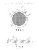
Other FAQs |
Patent application title: Pad Conditioner and Method for Making the Same
Inventors:
Tien-Yuan Yen
Agents:
WHYTE HIRSCHBOECK DUDEK S C;INTELLECTUAL PROPERTY DEPARTMENT
Assignees:
Origin: MILWAUKEE, WI US
IPC8 Class: AB24D1100FI
USPC Class:
51295
Abstract:
A method for making a pad conditioner, includes: (a) providing a first
substrate having a grain-mounting surface, and a plurality of diamond
abrasive grains, each of which has a retained portion and a cutting
portion with at least one sharp corner; (b) forming a plurality of
recesses in the first substrate, each of the recesses having a sharp
closed end and an enlarged open end, and diverging from the sharp closed
end to the enlarged open end in a manner to have a shape corresponding to
that of the sharp corner of each of the diamond abrasive grains; (c)
disposing each of the diamond abrasive grains in a respective one of the
recesses; (d) forming a second substrate on the grain-mounting surface of
the first substrate; and (e) removing the first substrate.Claims:
1. A method for making a pad conditioner, comprising:(a) providing a first
substrate having a grain-mounting surface, and a plurality of diamond
abrasive grains, each of which has a retained portion and a cutting
portion with at least one sharp corner;(b) forming a plurality of
recesses in the first substrate, each of the recesses being indented from
the grain-mounting surface, having a sharp closed end and an enlarged
open end opposite to the sharp closed end, and diverging from the sharp
closed end to the enlarged open end in a manner to have a shape
corresponding to that of the sharp corner of the cutting portion of each
of the diamond abrasive grains;(c) disposing each of the diamond abrasive
grains in a respective one of the recesses such that the cutting portion
of each of the diamond abrasive grains is received in the respective
recess, and that the retained portion of the respective one of the
diamond abrasive grains protrudes outwardly of the grain-mounting surface
of the first substrate;(d) forming a second substrate on the
grain-mounting surface of the first substrate in such a manner to enclose
and bond to the retained portion of each of the diamond abrasive grains;
and(e) removing the first substrate.
2. The method of claim 1, wherein the sharp closed end of each of the recesses has an angle ranging from 60 to 120.degree..
3. The method of claim 2, wherein each of the recesses has a depth relative to the grain-mounting surface of the first substrate that ranges from 0.25 to 0.95 times an average particle diameter of the diamond abrasive grains.
4. The method of claim 3, further comprising applying an adhesive in each of the recesses prior to step (c) so as to adhere the cutting portion of each of the diamond abrasive grains in the respective recess to the first substrate.
5. The method of claim 4, further comprising removing the adhesive after step (e) for exposing the cutting portions of the diamond abrasive grains.
6. The method of claim 5, wherein the applied adhesive in each of the recesses has a height relative to the sharp closed end, which is 0.1-0.9 times the depth of the recesses.
7. The method of claim 6, wherein the height of the applied adhesive in each of the recesses is 0.2-0.6 times the depth of the recesses.
8. A pad conditioner comprising:a substrate having a surface; anda plurality of diamond abrasive grains, each of which has a top portion protruding from said surface of said substrate, said top portion having a top end with a height relative to said surface of said substrate;wherein a height difference between a highest one of said top ends of said top portions of said diamond abrasive grains and a lowest one of said top ends of said top portions of said diamond abrasive grains is less than 40 μm.
9. The pad conditioner of claim 8, wherein said substrate is made from a resin.
Description:
CROSS-REFERENCE TO RELATED APPLICATION
[0001]This application claims priority of Taiwanese application no. 096129008, filed on Aug. 7, 2007.
BACKGROUND OF THE INVENTION
[0002]1. Field of the Invention
[0003]This invention relates to a method for making a pad conditioner, more particularly to a method involving forming pyramid and/or frusto-pyramid recesses for receiving sharp corners of diamond abrasive grains therein, respectively.
[0004]2. Description of the Related Art
[0005]Chemical Mechanical Polishing (CMP) is a well-known method that can effectively and reliably achieve global planarization of a wafer surface for under 0.5 μm technology. The growth of CMP techniques is attributed to a need to solve a light-focus problem of photolithography resulting from miniaturization of ICs, and to an increase in the number of layers of a multi-layered structure in ICs.
[0006]Performance of a CMP process is mainly affected by a pad conditioner, which is used to condition a polishing pad, i.e., to form a stable structure of pad asperities on the polishing pad. Wafer polishing occurs at an interface among the pad asperities, the wafer surface, and a slurry. Thus, the quality of the pad conditioner is a key factor for determining the performance of a CMP process, such as material removal rate, removal stability, planarization and defectivity.
[0007]Conventional methods for making the pad conditioner include attaching a plurality of diamond abrasive grains to a substrate surface using a patterned template or sieve. However, orientations of the diamond abrasive grains on the substrate surface are randomly disposed using the patterned template or sieve, which results in large height variations for top ends of the diamond abrasive grains relative to the substrate surface. An average height difference among the top ends of the diamond abrasive grains of the conventional pad conditioner thus formed usually ranges at least from 50 μm to 100 μm. Consequently, grooves formed in the polishing pad through the diamond abrasive grains of the conventional pad conditioner have various depths relative to the surface, which causes problems, such as polishing uniformity, high defectivity, and short service life. In addition, since the height difference is large, only a small portion of the diamond abrasive grains (i.e., working diamonds) are effective in forming the grooves in the polishing pad, which causes excessive wearing for the small portion of the diamond abrasive grains, and which results in a decrease in the cutting rate for forming the grooves in the polishing pad.
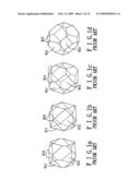
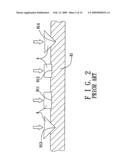
[0008]Moreover, commercial diamond abrasive grains are normally cuboctahedron in shape (see FIGS. 1a to 1d), and have sharp corners (i.e., pointed corners 913 and linear corners 914), and {111} and {100} faces 911, 912. FIG. 2 illustrates configurations of different grooves formed by the pointed corner 913, the linear corner 914, and the {111} and {100} faces 911, 912 of a diamond abrasive grain 4, respectively. Since the grooves formed by the pointed corner 913 and the linear corner 914 of the diamond abrasive grain 4 are narrow and deep, the pad asperities of the polishing pad 81 thus formed are thick and have a high mechanical strength, which, in turn, can achieve a high performance in material removal rate and a relatively low defectivity. On the contrary, since the grooves formed by the {111} and {100} faces 911, 912 of the diamond abrasive grain 4 are wide and shallow, the pad asperities of the polishing pad 81 thus formed are thin and have a weak mechanical strength, thereby resulting in a decrease in the material removal rate and an increase in the defectivity. Hence, the orientation of each of the diamond abrasive grains 4 is preferably arranged in a manner that the top end of each of the diamond abrasive grains 4, which is to be in contact with the polishing pad 81 during a cutting operation, is the pointed corner 913 or the linear corner 914. As such, the higher the number of the pointed corners 913 and/or the linear corners 914 disposed as the top ends of the diamond abrasive grains 4, the higher will be the performance of the pad conditioner in cutting the polishing pad 81, and the better will be the quality of the polishing pad 81 thus formed.
[0009]U.S. Pat. No. 6,769,975 discloses a method for forming a pad conditioner. The method involves forming a plurality of holes in a spacer, each of which has a cylindrical portion having a diameter smaller than the average particle diameter of the diamond abrasive grains, and a bowl-shaped upper portion enlarged in dimensions from the cylindrical portion to a top end of the spacer. After disposing the diamond abrasive grains in the holes, a bonding layer at an upper face of the spacer is formed so as to enclose and bond to the diamond abrasive grains, and the spacer is then removed to expose a portion of each of the diamond abrasive grains, that serves to cut a polishing pad. Although the quality of the pad conditioner thus formed is improved, there is still a need for further improving the aforesaid height difference problem and increasing the number of the pointed corners 913 and/or the linear corners 914 disposed as the top ends of the diamond abrasive grains 4 of the pad conditioner.
SUMMARY OF THE INVENTION
[0010]Therefore, the object of the present invention is to provide a method for making a pad conditioner that can overcome the aforesaid drawbacks associated with the prior art.
[0011]Another object of this invention is to provide a pad conditioner made by the method.
[0012]According to the present invention, a method for making a pad conditioner, comprises: (a) providing a first substrate having a grain-mounting surface, and a plurality of diamond abrasive grains, each of which has a retained portion and a cutting portion with at least one sharp corner; (b) forming a plurality of recesses in the first substrate, each of the recesses being indented from the grain-mounting surface, having a sharp closed end and an enlarged open end opposite to the sharp closed end, and diverging from the sharp closed end to the enlarged open end in a manner to have a shape corresponding to that of the sharp corner of the cutting portion of each of the diamond abrasive grains; (c) disposing each of the diamond abrasive grains in a respective one of the recesses such that the cutting portion of each of the diamond abrasive grains is received in the respective recess, and that the retained portion of the respective one of the diamond abrasive grains protrudes outwardly of the grain-mounting surface of the first substrate; (d) forming a second substrate on the grain-mounting surface of the first substrate in such a manner to enclose and bond to the retained portion of each of the diamond abrasive grains; and (e) removing the first substrate.
[0013]According to another aspect of this invention, a pad conditioner comprises: a substrate having a surface; and a plurality of diamond abrasive grains, each of which has a top portion protruding from the surface of the substrate. The top portion has a top end with a height relative to the surface of the substrate. A height difference between a highest one of the top ends of the top portions of the diamond abrasive grains and a lowest one of the top ends of the top portions of the diamond abrasive grains is less than 40 μm.
BRIEF DESCRIPTION OF THE DRAWINGS
[0014]Other features and advantages of the present invention will become apparent in the following detailed description of the preferred embodiment of this invention, with reference to the accompanying drawings, in which:
[0015]FIGS. 1a-1d are perspective views of commercial crystal diamond abrasive grains;
[0016]FIG. 2 is a fragmentary partly sectional view to illustrate configurations of cutting grooves in a polishing pad cut by different portions of the diamond abrasive grains;
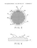
[0017]FIG. 3 is a schematic view of a die used for making recesses in a first substrate according to the preferred embodiment of a method for making a pad conditioner of this invention;
[0018]FIG. 4 is a sectional view taken along line IV-IV in FIG. 3;
[0019]FIG. 5 is a schematic view of the first substrate formed with the recesses using the die of FIG. 3 according to the preferred embodiment;
[0020]FIG. 6 is a sectional view taken along line VI-VI in FIG. 5;
[0021]FIG. 7 is a fragmentary sectional view to illustrate how an adhesive is applied in the recesses in the first substrate according to the preferred embodiment;
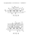
[0022]FIGS. 8 and 9 are fragmentary sectional views to illustrate how the diamond abrasive grains are disposed in the recesses in the first substrate according to the preferred embodiment;
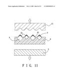
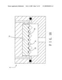
[0023]FIGS. 10 and 11 are sectional views to illustrate how a second substrate is formed to bond to the diamond abrasive grains according to the preferred embodiment;
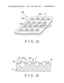
[0024]FIG. 12 is a fragmentary perspective view of the preferred embodiment of a pad conditioner formed according to the method of this invention;
[0025]FIG. 13 is a fragmentary partly sectional view of FIG. 12;
[0026]FIG. 14 is a microscope image of the pad conditioner of Example 1;
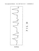
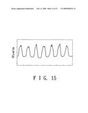
[0027]FIG. 15 is a surface profile-measuring graph showing heights of a portion of the diamond abrasive grains of Example 1;
[0028]FIG. 16 is a microscope image of the pad conditioner of Example 2;
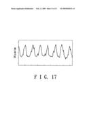
[0029]FIG. 17 is a surface profile-measuring graph showing heights of a portion of the diamond abrasive grains of Example 2;
[0030]FIG. 18 is a microscope image of the pad conditioner of Example 3; and
[0031]FIG. 19 is a surface profile-measuring graph showing heights of a portion of the diamond abrasive grains of Example 3.
DETAILED DESCRIPTION OF THE PREFERRED EMBODIMENT
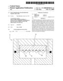
[0032]FIGS. 3 to 12 illustrate consecutive steps of the preferred embodiment of a method for making a pad conditioner 100 according to this invention. The method includes: (a) providing a first substrate 11 (see FIG. 5) having a grain-mounting surface 13, and a plurality of diamond abrasive grains 4, each of which has a retained portion 40 and a cutting portion with at least one sharp corner 913, 914 (see FIG. 8) and at least one of {111} and {100} faces 911, 912 (see FIGS. 1a to 1d); (b) forming a plurality of recesses 12 in the first substrate 11 (see FIGS. 5 and 6) using a die 2 (see FIGS. 3 and 4), each of the recesses 12 being indented from the grain-mounting surface 13, having a sharp closed end 121 and an enlarged open end opposite to the sharp closed end 121, and diverging from the sharp closed end 121 to the enlarged open end in a manner to have a shape corresponding to that of the sharp corner 913, 914 of the cutting portion of each of the diamond abrasive grains 4; (c) disposing each of the diamond abrasive grains 4 in a respective one of the recesses 12 (see FIGS. 8 and 9) such that the cutting portion of each of the diamond abrasive grains 4 is received in the respective recess 12, and that the retained portion 40 of the respective one of the diamond abrasive grains 4 protrudes outwardly of the grain-mounting surface 13 of the first substrate 11; (d) forming a second substrate 6 on the grain-mounting surface 13 of the first substrate 11 (see FIGS. 10 and 11) in such a manner to enclose and bond to the retained portion 40 of each of the diamond abrasive grains 4; and (e) removing the first substrate 11 (see FIG. 11).
[0033]Preferably, each of the diamond abrasive grains 4 is substantially cuboctahedron in shape.
[0034]By virtue of the geometric interference between each of the diamond abrasive grains 4 and a recess-defining wall of each of the respective recess 12, the shape of the recesses 12 thus constructed facilitates entrance of the sharp corner 913, 914 of the cutting portion of each of the diamond abrasive grains 4 into the sharp closed end 121 of the respective recess 12 during disposing of the diamond abrasive grains 4 in the respective recesses 12. In this embodiment, the recesses 12 are preferably pyramidal in shape, such as a right pyramid, a right cone and a right circular cone. Alternatively, the recesses 12 can be frusto-pyramidal in shape.
[0035]Preferably, the sharp closed end 121 of each of the recesses 12 has an angle ranging from 60° to 120°.
[0036]Preferably, each of the recesses 12 has a depth 122 relative to the grain-mounting surface 13 of the first substrate 11 that ranges from 0.25 to 0.95 times an average particle diameter of the diamond abrasive grains 4.
[0037]In this embodiment, the method further includes applying an adhesive 31 in each of the recesses 12 prior to step (c) so as to adhere the cutting portion of each of the diamond abrasive grains 4 in the respective one of the recesses 12 to the first substrate 11, and removing the adhesive 31 after step (e) for exposing the cutting portion of the diamond abrasive grains 4.
[0038]Preferably, application of the adhesive 31 to the first substrate 11 is conducted through one of screen printing, dispensing, spraying, and ink jet techniques.
[0039]Preferably, the applied adhesive 31 in the respective recess 12 has a height 311 relative to the sharp closed end 121, which is 0.1-0.9 times the depth 122 of the recesses 12, and more preferably, 0.2-0.6 times the depth 122 of the recesses 12. When the height 311 is less than 0.1 times the depth 122 of the recesses 12, the cutting portion of each of the diamond abrasive grains 4 is likely to fail to make contact with or to only make slight contact with the adhesive 31. When the height 311 is more than 0.9 times the depth 122 of the recesses 12, the function of the shape of each of the recesses 12, which serves to guide the sharp corner 913, 914 of the cutting portion of the respective diamond abrasive grain 4 to enter the sharp closed end 121 of the recess 12, will be completely lost.
[0040]Preferably, the adhesive 31 is selected from the group consisting of natural rubber, neoprene rubber, acrylic ester, silicone, polyurethane, and combinations thereof.
[0041]In this embodiment, the second substrate 6 is made from a resin. Preferably, the resin is one of a thermosetting resin and a thermoplastic resin. Preferably, the thermosetting resin is selected from the group consisting of unsaturated polyester resin, vinyl ester resin, epoxy resin, phenolic resin, bismaleimide, polyimide, and combinations thereof. More preferably, the thermosetting resin is epoxy resin.
[0042]In this embodiment, each of the diamond abrasive grains 4 has a particle diameter ranging from 10 mesh to 140 mesh.
[0043]Referring to FIGS. 12 and 13, the pad conditioner 100 formed according to the method of this invention includes: the second substrate 6 having a surface 62; and a plurality of the diamond abrasive grains 4, each of which has a top portion 45 protruding from the surface 62 of the substrate 6. The top portion 45 has a top end with a height 44 relative to the surface 62 of the substrate 6. A height difference between a highest one of the top ends of the top portions 45 of the diamond abrasive grains 4 and a lowest one of the top ends of the top portions 45 of the diamond abrasive grains 4 is less than 40 μm. Since the diamond abrasive grains 4 are randomly disposed on the first substrate 11 during preparation of the pad conditioner 100, probability for each of the sharp corners 913, 914 and at least one of the {111} and {100} faces 911, 912 to enter into the sharp closed end 121 or a lower space of the recess 12 is likely the same. However, by virtue of the shape of the recesses 12, most of the top ends of the top portions 45 of the diamond abrasive grains 4 of the pad conditioner 100 are the sharp corners 913, 914. The percentage of the number of the diamond abrasive grains 4 with the sharp corners 913, 914 as the top ends can be up to about 90%.
[0044]The merits of the method for making the pad conditioner 100 of this invention will become apparent with reference to the following Examples.
EXAMPLE
Example 1
[0045]A die 2 made by wire cutting techniques was provided to imprint a plastic substrate 11 so as to form a plurality of pyramidal recesses 12 therein (FIGS. 3-5). The die 2 was made from a stainless steel plate 21 that was formed with a plurality of right pyramids 22 protruding from a die surface 211 of the stainless steel plate 21 having a diameter of 110 mm and a thickness of 30 mm. The right pyramids 22 were distributed over a region with a diameter of 100 mm on the die surface 211. The distance between tip ends 221 of each two adjacent ones of the right pyramids 22 was 700 μm. The tip end 221 of each of the right pyramids 22 defined an angle of about 90° and a height of 350 μm relative to the die surface 211. The plastic substrate 11 was made from polypropylene, and had a diameter of 110 mm and a thickness of 0.4 mm. A pressure of 10 MPa was applied on the die 2 to imprint the plastic substrate 11 so as to form about 15785 pyramidal recesses 12, each of which defined an angle of 90°, a depth 122 of 225 μm relative to a surface 13 of the plastic substrate 11, and a width 123 of 450 μm. The distance between the sharp closed ends 121 of each two adjacent ones of the pyramidal recesses 12 was 700 μm.
[0046]It is noted that formation of the pyramidal recesses 12 can also be conducted through injection molding or die casting, or through electronic discharge machining, ultrasonic machining, micro-milling, laser machining, electron beam machining, and ion beam machining techniques, which can dispense with the die 2.
[0047]A stainless steel screen 32 having a thickness of 50 μm and formed with circular holes 321 of 0.2 mm in diameter was disposed on the plastic substrate 11. An adhesive 31 was formed by mixing a water-based acrylic pressure sensitive adhesive (SP-7533, produced by 3M CO.) and deionized water at a weight ratio of 1:1. The adhesive 31 was applied to the stainless steel screen 32, and was forced into the pyramidal recesses 12 using a scraper 34. The plastic substrate 11 was then placed in a hot recirculating oven under a temperature of 50° C. for 15 min. The height 311 of the adhesive 31 in the recess 12 relative to the sharp closed end 121 of the recess 12 was about 50 μm (FIG. 8).
[0048]A plurality of the diamond abrasive grains 4 having a cuboctahedron shape with a particle diameter ranging from 40 mesh to 45 mesh (SDB1100, produced by ELEMENTSIX) were distributed over the plastic substrate 11, and were moved into the recesses 12 using an acrylic brush so as to be bonded to the adhesive 31 in the recesses 12.
[0049]It is noted that moving of the diamond abrasive grains 4 into the recesses 12 can also be conducted using an oscillator.
[0050]Excess diamond abrasive grains 4 were removed from the plastic substrate 11 using the brush or using the oscillator.
[0051]A pressing plate 35 of silicon was then disposed on the diamond abrasive grains 4 on the plastic substrate 11, and a pressure of 0.2 MPa was subsequently applied on the pressing plate 35 to force the diamond abrasive grains 4 into the recesses 12 so as to ensure that the sharp corners 913, 914 of the diamond abrasive grains 4 are fully received in the sharp closed ends 121 of the recesses 12 (FIG. 7).
[0052]The pressing plate 35 can also be made from an elastomeric material, such as natural rubber or polyvinyl chloride.
[0053]Preferably, the pressure applied on the pressing plate 35 ranges from 0.1 MPa to 1 MPa.
[0054]The plastic substrate 11 having the diamond abrasive grains 4 attached thereto was disposed in a mold 5. The mold 5 was vacuumed to lower than 1 mbar. A thermosetting resin was then injected into the mold 5 so as to form the second substrate 6 to bond to the diamond abrasive grains 4. The thermosetting resin was formed by mixing epoxy resin (EPOFIX RESIN, produced by STRUERS A/S Co.) and a curing agent (EPOFIX HARDENER, produced by STRUERS A/S Co.) at a weight ratio of 25:3.
[0055]It is noted that vacuuming of the mold 5 has an advantage in removing air in the mold 5 and the recesses 12 so as to prevent formation of pores between the diamond abrasive grains 4 and thermosetting resin.
[0056]After the thermosetting resin was hardened under room temperature for 12 hours, the plastic substrate 11 together with the diamond abrasive grains 4 and the second substrate 6 (FIG. 11) was removed from the mold 5, and was subsequently removed from the second substrate 6. The diamond abrasive grains 4 on the second substrate 6 was then dipped in a methyl ethyl ketone solvent for 15 min, and was cleaned with a scrubbing roller so as to remove the adhesive 31 on the diamond abrasive grains 4 for exposing the cutting portions of the diamond abrasive grains 4. After further cleaning using an ultrasonic instrument and drying through compressed air, a pad conditioner 100 including the second substrate 6 and the diamond abrasive grains 4 was obtained.
[0057]It is noted that a release agent, such as polyvinyl alcohol, polytetrafluoroethylene, dimethyl polysiloxane and wax, is preferably used to coat an inner surface of the mold 5 and the surface 13 of the plastic substrate 11 so as to facilitate separation of the plastic substrate 11 from the mold 5. Removal of the adhesive 31 can also be conducted through soaking in ethanol or dimethyl benzene solvent, or water washing with a non-abrasive roller.
[0058]Since the thermosetting resin injected into the mold 5 also fills the remaining portion 124 of each recess 12 (see FIG. 8) in the plastic substrate 11, which is not occupied by the adhesive 31 and the diamond abrasive grain 4, a protrusion 61 of the thermosetting resin is formed and protrudes from the second substrate 6 after formation of the second substrate 6, thereby enhancing bonding between the second substrate 6 and the diamond abrasive grains 4.
[0059]FIG. 14 is a microscope image showing a configuration of the pad conditioner 100 of Example 1 at 60× magnification.
[0060]By examining about 1000 diamond abrasive grains 4 of the pad conditioner 100 via observing the microscope image, the number of the diamond abrasive grains 4 with the sharp corners 913, 914 as the top ends was 890, i.e., the percentage of the number of the diamond abrasive grains 4 with the sharp corners 913, 914 as the top ends was 89%.
[0061]FIG. 15 is a surface profile-measuring graph showing the heights 44 of a portion of the diamond abrasive grains 4 of Example 1 using a surface profile-measuring instrument (MITUTOYO, SURFTEST SV-400). The parameters set for measuring the heights 44 of the diamond abrasive grains 4 are as follows: The height to be measured was 600 μm. The resolution was 0.1 μm. The length to be measured was 5.0 mm. Each peak represented the height 44 of each of the measured diamond abrasive grains 4. The maximum height difference between the highest peak and the lowest peak was less than 25 μm, which is an indication of relatively uniform heights 44 for the diamond abrasive grains 4 on the pad conditioner 100 of Example 1.
Example 2
[0062]The pad conditioner 100 of Example 2 was prepared by steps similar to those of Example 1, except that the height 311 of the adhesive 31 relative to the sharp closed end 121 of the recess 12 was about 150 μm (see FIG. 8).
[0063]FIG. 16 is a microscope image showing a configuration of the pad conditioner 100 of Example 2 at 60× magnification. Since the height 311 of the adhesive 31 in the recess 12 of Example 2 was higher than that of Example 1, the height of the protrusions 61 of Example 2 was smaller than that of Example 1. By examining about 1000 diamond abrasive grains 4 of the pad conditioner 100 via observing the microscope image, the number of the diamond abrasive grains 4 with the sharp corners 913, 914 as the top ends was 810, i.e., the percentage of the number of the diamond abrasive grains 4 with the sharp corners 913, 914 as the top ends was 81%.
[0064]FIG. 17 is a surface profile measuring graph showing the heights 44 of a portion of the diamond abrasive grains 4 of Example 2 using the surface profile-measuring instrument (MITUTOYO, SURFTEST SV-400). The parameters set for the measurement were the same as those of Example 1. The maximum height difference was 15 μm, which is an indication of relatively uniform heights 44 for the diamond abrasive grains 4 on the pad conditioner 100 of Example 2.
Example 3
[0065]The pad conditioner 100 of Example 3 was prepared by steps similar to those of Example 1, except for the manners of making the plastic substrate 11 and filling the adhesive 31.
[0066]The die 2 was formed by V-shaped groove grinding machining techniques, in which an annular region (which has an inner radius of 23.6 mm and an outer radius of 51.3 mm) of a stainless steel (SUS420) body was cut and ground from three directions (each direction pair forming an angle of 120 degrees) so as to form a plurality of V-shaped grooves in each direction. The distance between each two adjacent ones of the V-shaped grooves was 1.23 mm. The grinding angle was 70.52°. The depth 122 of the V-shaped grooves was about 0.577 mm.
[0067]A pressure of 10 MPa was then applied on the die 2 thus formed to imprint the plastic substrate 11 (polypropylene), which had a diameter of 110 mm and a thickness of 1.0 mm, so as to form 7192 right-cone recesses 12 therein, each of which defined an angle of 90°, and a depth 122 of 350 μm relative to the surface 13 of the plastic substrate 11.
[0068]The adhesive 31 was then filled in the recesses 12 through dispensing techniques using a needle. An inner diameter of the needle of the dispensing machine was 0.26 mm. The adhesive 31 was formed by mixing water-based acrylic pressure sensitive adhesive (SP-7533, produced by 3M CO.) and deionized water at a weight ratio of 2:1. The height 311 of the adhesive 31 relative to the sharp closed end 121 of the recess 12 was about 200 μm after drying. The particle diameter of the diamond abrasive grains 4 ranged from 30 mesh to 35 mesh (SDB1100, produced by ELEMENTSIX).
[0069]FIG. 18 is a microscope image showing a configuration of the pad conditioner 100 of Example 3 at 60× magnification. By examining about 500 diamond abrasive grains 4 of the pad conditioner 100 via observing the microscope image, the number of the diamond abrasive grains 4 with the sharp corners 913, 914 as the top ends was 415, i.e., the percentage of the number of the diamond abrasive grains 4 with the sharp corners 913, 914 as the top ends was 83%.
[0070]FIG. 19 is a surface profile measuring graph showing the heights 44 of a portion of the diamond abrasive grains 4 of Example 3 using the surface profile-measuring instrument (MITUTOYO, SURFTEST SV-400). The parameters set for the measurement were the same as those of Example 1, except that the length to be measured was 7.5 mm. The maximum height difference was 20 μm.
[0071]Since the maximum height difference is relatively small for the pad conditioner 100 of this invention, more diamond abrasive grains 4 can serve as the working diamonds as compared to the conventional pad conditioner, which improves the cutting rate, removal stability, and service life of the polishing pad processed by the pad conditioner 100.
[0072]Moreover, the percentage of the number of the diamond abrasive grains 4 with the sharp corners 913, 914 as the top ends is much higher as compared to that of the conventional pad conditioner, thereby improving production of good quality polishing pads.
[0073]With the invention thus explained, it is apparent that various modifications and variations can be made without departing from the spirit of the present invention. It is therefore intended that the invention be limited only as recited in the appended claims.
User Contributions:
comments("1"); ?> comment_form("1"); ?>Inventors list |
Agents list |
Assignees list |
List by place |
Classification tree browser |
Top 100 Inventors |
Top 100 Agents |
Top 100 Assignees |
Usenet FAQ Index |
Documents |
Other FAQs |
User Contributions:
Comment about this patent or add new information about this topic:
Images included with this patent application:
 |  |
 |  |
 |  |
 |  |
 |  |
 |  |
 |  |
 |
| Similar patent applications: | |
| Date | Title |
|---|---|
| 2010-06-17 | Polishing pad having insulation layer and method for making the same |
| 2011-05-12 | Coated cutting insert and method for making the same |
| 2011-12-08 | Brazed diamond tools and methods for making the same |
| 2012-08-02 | Brazed diamond tools and methods for making the same |
| 2009-05-14 | Impregnated drill bits and methods for making the same |
| New patent applications in this class: | |
| Date | Title |
|---|---|
| 2016-06-30 | Abrasive articles and methods for forming same |
| 2016-06-30 | Abrasive articles and methods for forming same |
| 2016-06-30 | Abrasive tools and methods for forming same |
| 2016-06-30 | Colored abrasive articles and method of making colored abrasive articles |
| 2016-06-23 | Shaped abrasive particles and method of forming same |
| Top Inventors for class "Abrasive tool making process, material, or composition" | |
| Rank | Inventor's name |
|---|---|
| 1 | Srinivasan Ramanath |
| 2 | Rachana Upadhyay |
| 3 | Anthony A. Digiovanni |
| 4 | Doruk O. Yener |
| 5 | Jennifer H. Czerepinski |